Creating various 3D Models like Furniture, Footing, Girder, Column drop with panel and Gable Wall in AutoCad
1. Create a 3D Furniture element as shown in the Figure. Assume dimensions which are missing.
Aim: To create a 3D furniture element as shown in the figure and to provide dimensions to the model.
Introduction: The given figure is 3d model hence the type of drawing model layout is changed from drafting and annotation to 3d modelling to design a 3d model. Imperial system is used as the given drawing is in feet and inches.
Steps:
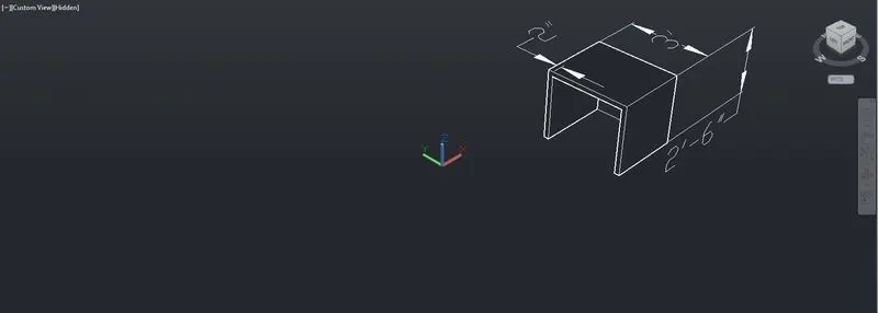
- Initially the model space is kept in front view and the ucs is alligned as xy plane
- Then a rectangle of size 3'x2'-6" is drawn and a offset of 2" is done.
- Then the view is changed to default
- Then using the extrude command the drawn model is converted into 3d by extruding in the x direction.
- Then using the subtract command the bottom face of the large rectangle is subtracted by keeping the diagram in the bottom view.
- A definite dimension style is fixed and the dimensions are marked for the created model
- The dimensions are marked by keeping the ucs on the faces of the 3d model created to mark the dimenion in the exact plane required.
Results: The given 3d model is created and usage of 3d options such as extrude, subtract are learnt. The usage and placing of UCS icon for drawing and dimensioning are also learnt.
2. Create the 3d Model of an Isolated footing as shown in Figure.
Aim: To Create the 3d Model of an Isolated footing as shown in figure.
Introduction: The given model consists of a isolated footing with the column placed on it. The given footing is considered as a square of size 2'x2' . The given drawing is drawn in imperial system as the drawing is given in feet and inches.
Steps:
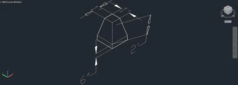
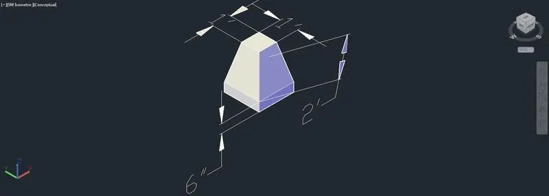
- Initially in the top view a rectangle of 2'x2' is drawn and a another rectangle of 1'x1' is drawn at the centre of the previous rectangle drawn.
- Then the view is changed to default and the inner rectangle is moved upwards in z direction at a height of 2'.
- Then the the two rectangles are connected using the line tool.
- Then bigger rectagle is extruded in the -z direction with 6" distance.
- Then using planar tool the top of the 1'x1' rectangle is covered to entirely make it as a solid structure.
- Then using the ucs command face option the ucs is placed at the face of the object as per the requirement and the dimensions are marked after fixing a definite dimension style and the diagram is finished.
Results: The given isolated footing is created sucessfully and the better usage of ucs as per the view and dimensions and extrude command is used and learnt sucessfully.
3. Create the 3D view of the AASTHO Type Girder.
Aim: To create the 3D view of the AASTHO Type Girder and present and mark the dimensions of the figure as per the requirement.
Introduction: The given drawing is a steel girder with a top flange width of 1' and a bottom flange width of 1'-6" with a web height of 1'-6" and it is a I section. The width of the girder is given as 10'. The drawing is drawn in imperial system as the drawing is given in feet and inches.
Steps:
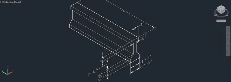
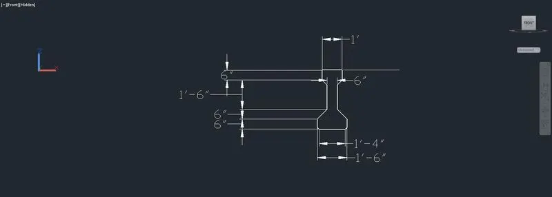
- Initially in the front view a line of 1' is drawn
- Then using the line tool at distance of 3' in the downwards direction another line of width 1'-6" is drawn
- Then at the middle of the two lines a line is drawn and a offset of 3" is done on both sides of the drawn middle line to set the width of the web
- Then at the end of the top and bottom lines a line of 6" is drawn.
- Then using chamfer command the drawn extension lines are connected with the web
- The top flange is connected with 3" distance on both sides with chamfer command.
- The bottom flange is connected with the web with 6" distance on both sides using the chamfer command.
- Then using a chamfer distance of 2" the bottom flange is chamfered at the edges.
- Finally the middle line is deleted and the view is restored to its default view.
- Then using the region command both the flanges and web are united to covert into a single component.
- Then using the extrude command with distance 10' the girder width is given.
- Finally after fixing a definite dimension style the dimensions are marked after placing the ucs on the object and the plane is fixed as per the requirement.
Results: The given girder figure is created sucessfully and the commands such as region,extrude,chamfer are used sucessfully.
4. Create a 3d Model of a drop column with panel as shown in section and isometric view.
Aim: To create a 3d Model of a drop column with panel as shown in section and isometric view.
Introduction: The given figure is a column with a panel at the bottom of size 4'-6" and the column size is 1'-6". The two views needed to submit are section view and a isometric conceptual view of the figure. The drawing is drawn in imperial system as the given diagram is in feet and inches.
Steps:
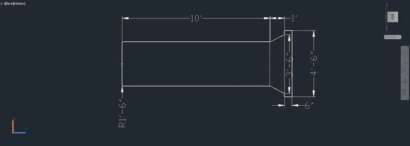
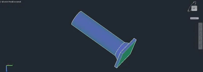
- Initially a circle of radius 1'-6" is drawn and using the extrude command the circle is extruded in bottom at a distance of 10'
- Then the bottom view is fixed and a cone is drawn at the bottom with the command cone
- The bottom of the cone is placed on the bottom of the circle and the bottom radius is given as 1'-6" and top as 3'-6" with height as 1'
- Then a square of size 4'-6" is drawn using the rectangle command and placed at the top of the cone
- Further, the view is restored to its default and using extrude command the bottom square i.e the panel is given a depth of 6"
- Then using the section command the created column with panel object is subjected to section by cutting in half right exaactly at the middle
- Then the view is kept at the right with xz plane in accordance of the view
- After defining the dimension style the dimensions are marked and the ucs is kept on the object and the plane is fixed as per the requirement
- Furthermore the isometric view image is provided by selecting the conceptual style and the object is rotated with 3dorbit command to set the required view.
Results: The drop column with the panel is created sucessfully and the comands such as section,3d orbit are used sucessfully and the required two views of the object are provided.
5. Create the 3d model of a wall as shown in Figure. Consider wall thickness as 9”.
Aim: To create the 3d model of a wall as shown in figure with the wall thickness as 9”.
Introduction: The given gabble wall is front view of the house with a door of 3' width and 7' height and the total width and height of the wall are 10' and 12'-6" respectively. The given drawing is drawn in imperial system as the given figure is in feet and inches.
Steps:
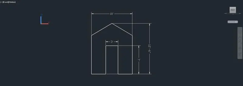
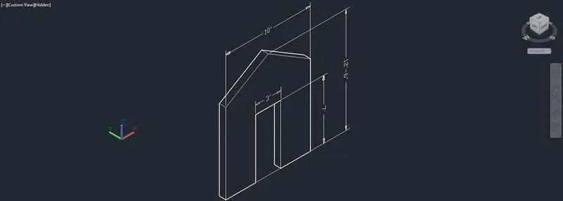
- Initially front view is fixed with the xz plane in accordance with the view by changing the ucs from the ribbon
- Then a line rectangle of size 12'-6" x 10' is drawn.
- Then at the middle a line is drawn and using the offset command at distance of 1.5' the middle line is offseted on either sides
- Then from the bottom with the distance of 7' offset of bottom line is done.
- Then the lines are trimmed off using the trim command to provide the door opeining.
- Then with the distance of 10' the bottom line is subjected to offset again using the offset command
- Then from the top middle two inclined lines are drawn to connect the edges of the offseted line using the line command and the extra lines are trimmed off using the trim command.
- After restoring to the default view using extrude command the drawn wall is provided with a thickness of 9"
- Then after setting the dimension style dimensions are marked by placing the ucs on the object and fixing the plane as per the requirement.
Results: The given gabble wall is created sucessfully as per the required size and with a thickness of 9".