Creating various 3D Models like Furniture, Footing, Girder, Column drop with panel and Gable Wall in AutoCad
|
Creating various 3D Models like Furniture, Footing, Girder, Column drop with panel and Gable Wall in AutoCad |
PROBLEM 1
- Aim :- To Create a 3D Furniture element as shown in the Figure
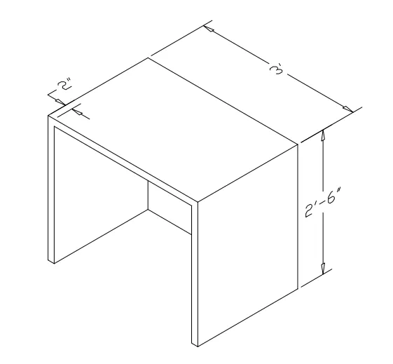
- Procedure :-
- Click on AutoCAD application and open this application
- Type QNEW in command bar and enter
- Select default setting as Imperial
- In default setting click on use a wizard and in that advance setting and set unit as Architectural and precision as 0’0” and press Next
- Set Angle as Decimal Degree and precision as 0 and click next
- Set Angle Measure as EAST and press NEXT
- Set Angle Direction as Counter-Clockwise and press NEXT
- Set Area by providing Length as 50’ and Width as 50’
- Press finish
- Keep ortho, Object snap >ON
- Keep Snap and Grid > Off
- Un+enter
- Type > Architectural, Precision > 0’0”
- Units to scale inserted content > Inches
- Enter
- Select workspace switching > 3D Modelling
- Select Visual style control > 2D Wireframe
- Take 3D Orbit command
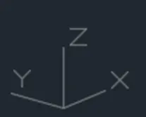
- Select view such as the UCS direction is as shown below
- Take line command
- Select first point > Anywhere in the drawing
- Line specify next point > @0,0,2’6” > Enter
- Line specify next point > @0,3’,0> Enter
- Line specify next point > @0,0,-2’6” > Enter
- Line specify next point > @0,-2”,0 > Enter
- Line specify next point > @0,0,2’4” > Enter
- Line specify next point > @0,-2’8”,0 > Enter
- Line specify next point > @0,0,-2’4” > Enter
- Line specify next point > @0,-2”,0 > Enter
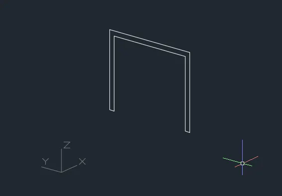
- It will shows the following result
- Take a rectangle command
- Specify first corner point > Click on top left corner point
- Click > Dimension
- Specify Length > 2’2”
- Specify width > 3’
- Enter
- Use line command to connect the rectangle as shown below
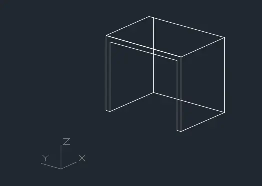
- Take 3D face command
- Specify all the four point of the top rectangle
- Enter > Hide > Enter
- Similarly do the 3D face command to all the faces of the drawing
- Click on ANNOTATION tab
- Click on Dimension
- Click > Manage dimension style
- New
- Style name > 3D
- Set the characteristics of dimensions as
- Select the yellow colour for the dimension style and extension line
- Select arrowhead size as 4”
- Select the text as green colour
- Then select linear dimensions
- Provide the linear dimension
- It will shows the following result
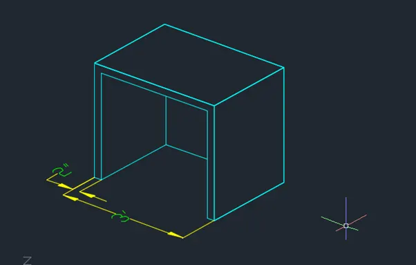
PROBLEM 2
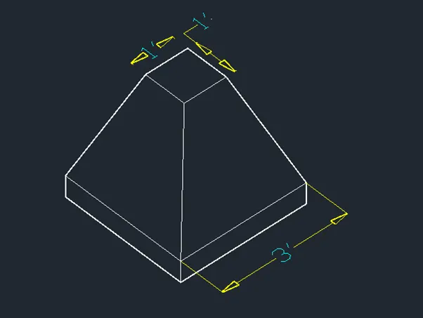
- Aim :- To Create a 3D Model of an Isolated Footing as shown in the below figure
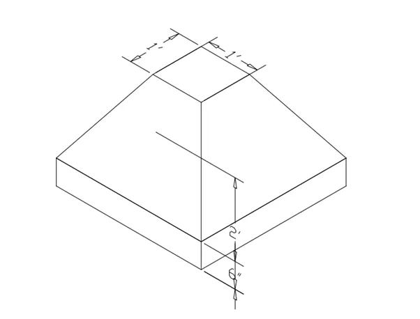
- Procedure :-
- Click on AutoCAD application and open this application
- Type QNEW in command bar and enter
- Select default setting as Imperial
- In default setting click on use a wizard and in that advance setting and set unit as Architectural and precision as 0’0” and press Next
- Set Angle as Decimal Degree and precision as 0 and click next
- Set Angle Measure as EAST and press NEXT
- Set Angle Direction as Counter-Clockwise and press NEXT
- Set Area by providing Length as 5’ and Width as 5’
- Press finish
- Keep ortho, Object snap >ON
- Keep Snap and Grid > Off
- Un+enter
- Type > Architectural, Precision > 0’0”
- Units to scale inserted content > Inches
- Enter
- Select workspace switching > 3D Modelling
- Select Visual style control > 2D Wireframe
- Take 3D Orbit command
- Select view such as the UCS direction is as shown below
- Take rectangle command
- Specify corner point anyehere in the drawing
- Click > Dimension
- Specify Length > 3’
- Specify Width > 3’
- Enter
- Take rectangle command
- Specify corner point anyehere in the drawing
- Click > Dimension
- Specify Length > 1’
- Specify Width > 1’
- Enter
- By keeping object snap on
- Keep the small rectangle such as, both rectangle shows the same centre point
- Take move command
- Select object > Click on small rectangle
- Move it in a Z axis at a distance of 2’6”
- Take the line command
- Join all the corners of the both rectangle as shows below

- Take 3D face command
- Specify all the four point of the top rectangle
- Enter > Hide > Enter
- Similarly do the 3D face command to all the faces of the drawing
- Take the extrude command
- Select object > Click on the bottom rectangle
- Specify extrude height > 6”
- Enter
- Change the visual style control > Hidden
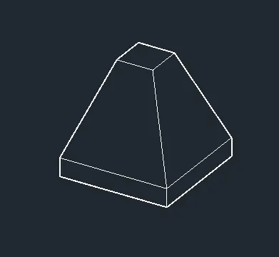
- Click on ANNOTATION tab
- Click on Dimension
- Click > Manage dimension style
- New
- Style name > 3D
- Set the characteristics of dimensions as
- Select the yellow colour for the dimension style and extension line
- Select arrowhead size as 4”
- Select the text as cyan colour
- Then select linear dimensions
- Provide the linear dimension
- It will shows the following result
- Result :-
PROBLEM 3
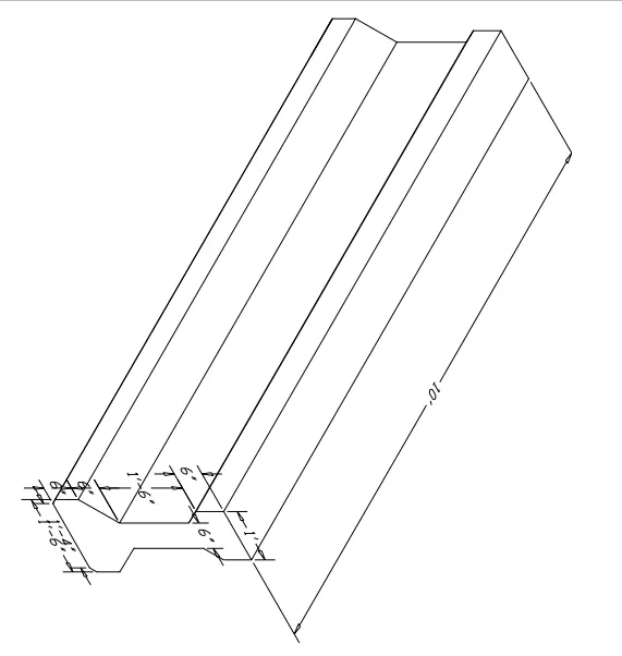
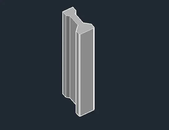
- Aim :- To Create the 3D view of the AASTHO Type Girder as per shown in the below figure
- Procedure :-
- Click on AutoCAD application and open this application
- Type QNEW in command bar and enter
- Select default setting as Imperial
- In default setting click on use a wizard and in that advance setting and set unit as Architectural and precision as 0’0” and press Next
- Set Angle as Decimal Degree and precision as 0 and click next
- Set Angle Measure as EAST and press NEXT
- Set Angle Direction as Counter-Clockwise and press NEXT
- Set Area by providing Length as 50’ and Width as 50’
- Press finish
- Keep ortho, Object snap >ON
- Keep Snap and Grid > Off
- Un+enter
- Type > Architectural, Precision > 0’0”
- Units to scale inserted content > Inches
- Enter
- Select workspace switching > 3D Modelling
- Select Visual style control > 2D Wireframe
- Select view control > Top
- Take line command
- Select first point > Anywhere in the drawing
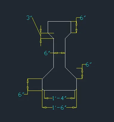
- Line specify next point > 1’6” > Enter keeping curser right side
- Line specify next point > 6” > Enter keeping curser Up side
- Enter
- Take the offset command
- Specify distance as 6”
- Select object > Click on the horizontal line
- Similarly by using the line and offset command complete the plan as shown below
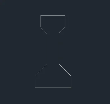
- Take the fillet command
- Select fillet radius > 1”
- Select multiple
- Select the object which have to give the fillet command as per shown below
- Click on ANNOTATION tab
- Click on Dimension
- Click > Manage dimension style
- New
- Style name > 3D
- Set the characteristics of dimensions as
- Select the yellow colour for the dimension style and extension line
- Select arrowhead size as 4”
- Select the text as cyan colour
- Then select linear dimensions
- Provide the linear dimension
- It will shows the following result
- Take boundary command
- Dialogue box will open
- Click on > Pick a point
- Click on the internal portion of diagram
- Enter
- Take the extrude command
- Select object > Click on the bottom rectangle
- Specify extrude height > 10’
- Enter
- Change the visual style control > Shaded with edges
- It will shows the following result
- Result :-
PROBLEM 4
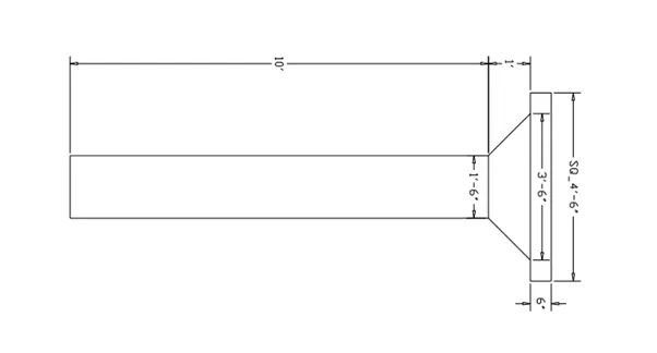
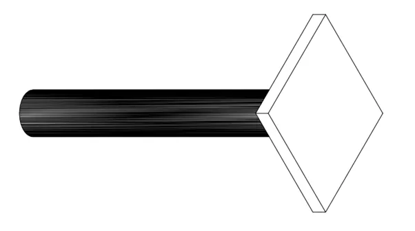
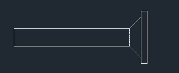
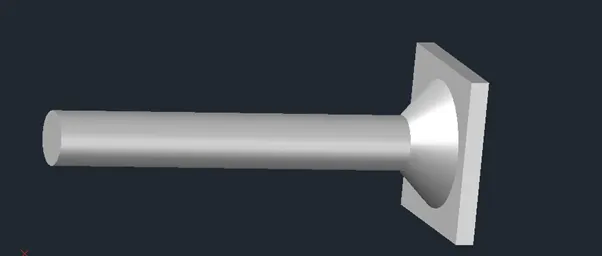
- Aim :- To Create a 3d Model of a drop column with panel as shown in section and isometric view
- Procedure :-
- Click on AutoCAD application and open this application
- Type QNEW in command bar and enter
- Select default setting as Imperial
- In default setting click on use a wizard and in that advance setting and set unit as Architectural and precision as 0’0” and press Next
- Set Angle as Decimal Degree and precision as 0 and click next
- Set Angle Measure as EAST and press NEXT
- Set Angle Direction as Counter-Clockwise and press NEXT
- Set Area by providing Length as 50’ and Width as 50’
- Press finish
- Keep ortho, Object snap >ON
- Keep Snap and Grid > Off
- Un+enter
- Type > Architectural, Precision > 0’0”
- Units to scale inserted content > Inches
- Enter
- Select workspace switching > 3D Modelling
- Select Visual style control > 2D Wireframe
- Select view control > Top
- Take rectangle command
- Select first corner point > Anywhere in the drawing
- Click > Dimension
- Specify Length > 4’6”
- Specify width > 4’6”
- Enter
- Take a circle command
- Specify centre > anywhere
- Click > diameter
- Specify diameter > 3’6”
- Enter
- Take a circle command
- Specify centre > Same centre
- Click > diameter
- Specify diameter > 1’6”
- Enter
- Take move command
- Select object > Click the smaller circle
- Specify distance > 1’
- And move it along Z axis
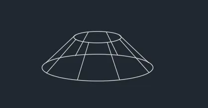
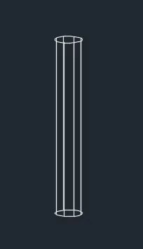
- Take the extrude command and extrude the smaller circle as per shown below
- Take a circle command
- Specify centre > anywhere
- Click > diameter
- Specify diameter > 1’6”
- Enter
- Make it region
- Take extrude command
- Select object > Click on the latest circle drawn
- Specify Extrude height > 10’
- Enter
- Take region command
- Select object > Click on the rectangle
- Take extrude command
- Extrude object > Click the rectangle
- Extrude height > 6”
- Enter
- Take move command
- Move the above two diagram at the centre of rectangle by keeping object snap on
- It will shows following result
- Result :-
PROBLEM 5
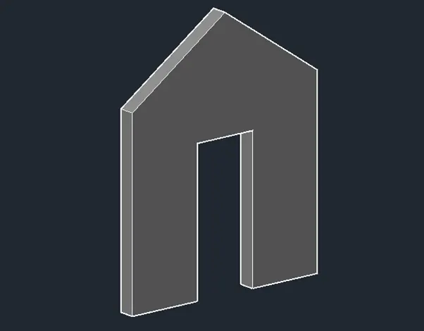
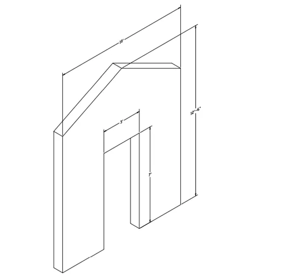
- Aim :- To Create the 3d model of a wall as shown in Figure having the thickness as 9”
- Procedure :-
- Click on AutoCAD application and open this application
- Type QNEW in command bar and enter
- Select default setting as Imperial
- In default setting click on use a wizard and in that advance setting and set unit as Architectural and precision as 0’0” and press Next
- Set Angle as Decimal Degree and precision as 0 and click next
- Set Angle Measure as EAST and press NEXT
- Set Angle Direction as Counter-Clockwise and press NEXT
- Set Area by providing Length as 50’ and Width as 50’
- Press finish
- Keep ortho, Object snap >ON
- Keep Snap and Grid > Off
- Un+enter
- Type > Architectural, Precision > 0’0”
- Units to scale inserted content > Inches
- Enter
- Select workspace switching > 3D Modelling
- Select Visual style control > 2D Wireframe
- Take 3D Orbit command
- Select view such as the UCS direction is as shown below
- Take line command
- Select first point > Anywhere in the drawing
- Line specify next point > @3’6”,0,0 > Enter
- Line specify next point > @0,0,7’ > Enter
- Line specify next point > @3’,0,0 > Enter
- Line specify next point > @0,0,-7’ > Enter
- Line specify next point > @3’6”,0,0 > Enter
- Line specify next point > @0,0,9’ > Enter
- Line specify next point > @-10,0,0 > Enter
- Line specify next point > @0,0,-9’ > Enter
- From the bottom midpoint of the door
- Draw the line of 12’6”
- Join the corners of the top wall to top og the line drawn
- Erase the unwanted line

- Take a Region command
- Select the object > Select whole diagram
- Enter
- Take extrude command
- Select the object > Select the object which is regioned
- Specify extrude height > 9”
- Enter by extruding it along Y-Axis
- It will shows the following results
- Result :-
Visual Style control > Shades of Grey