Creating various 3D Models like Furniture, Footing, Girder, Column drop with panel and Gable Wall in AutoCad
AIM-: drafting the 3D wireframe elements given in the question Figures, using the 3D modelliing in AutoCAD MAKING THE SURFACE of the planes and hide the backside lines.
Figure 1.
Drafing Prcedure-:
- open Autocad, UN Command Set the unjt as Engineering with precison 0 and Inches as input unit.
- View sected as default and than drafe the 2D frame of given figure.
- Switched workspace as 3D modelling and
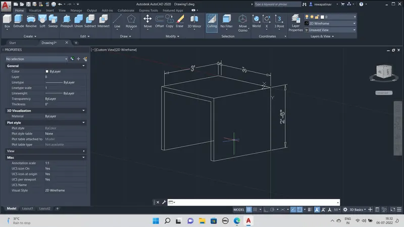 .
. - drawn a line of 3'
- and Boudary command for 2D frame and than sweep command is used
- object selected 2d frame and than path as 3' line
- Following gementry obtained.
- 3D face (3F) command used and made the surfaces at the top and side panels to hide the bakside lines.
Figure 2.
Pocedure
Drawn a rectangle or square of size 2;
Than offset rectangle inside with 6" to get the square of 1'*1'
Than moved the 1' square in Z direction given cordinates 0,0,1'6"
Than Copy 2' Square in Z direction at 6"
Line command to join the points to get the following waireframe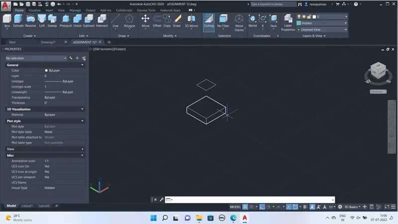
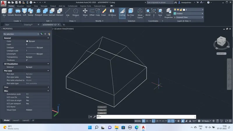
Than 3D face command used to draw the surfaces and then HIDE command used.
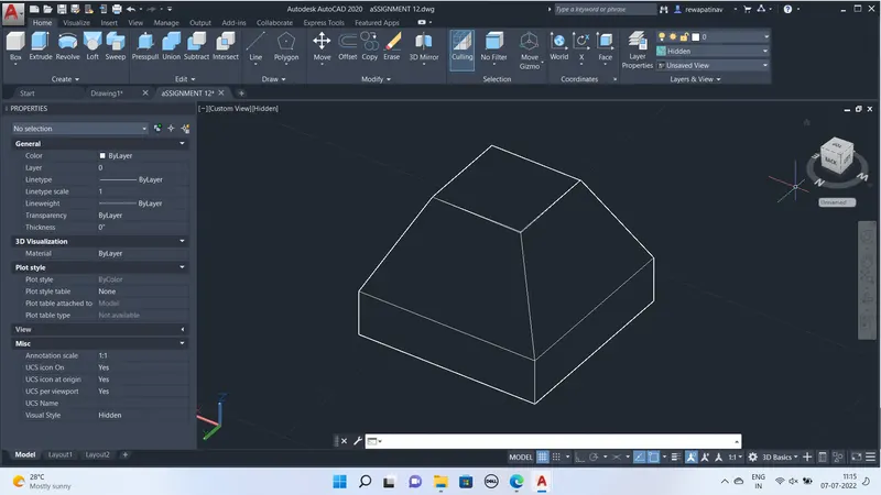
Figure 3.
AIM -: Creating the AASTHO Type Girder in 3D
Procedure ;-
Created the cross section as given in the figure with all the dimensions
Make the Region or a Polyline geometry
drawn a line of length of 10'
Sweep Command used to create the geopmetry as in snip
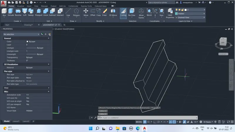
Figure5
Aim;_ create the Drop panel as shown in the figure
Procedure ;-
- Drawn a Circle in 2d view in X-y plane of radius 9"
- Line drawan in Z direction length of 10'
- Sweep command taken object as cirdle and path as line selected
- than Cone Command center at cirle center and than Top radius option selected and than diameter given 3'6" and Height of 1'
- Move this cone to the top of the column cordinates given @0,0,10'
- Rectrangle is create at bottom as lies on cylinders center size of square is 4'6x4'6 and than extrude with height of 6
- than move the box at the height of 11'
- figure can see in the snap
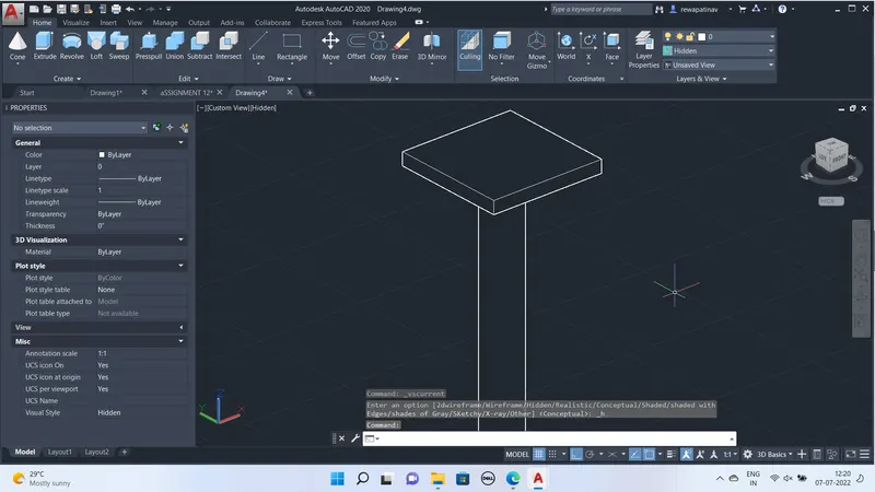
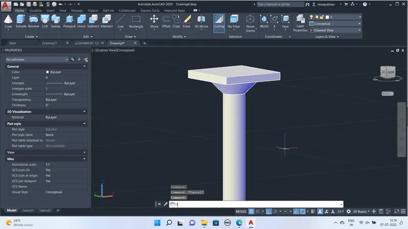
Figure 5.
Aim:-
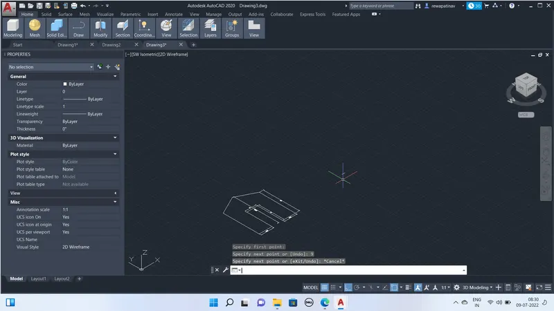
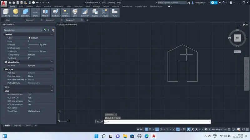
Creating the 3D model of wall considering the wall thickness as 9" given
Procedure :-
- Start CAD and Un Engineering and inches
- Default 2D view workspace and than drawn the Front part of the wall As the dimensions given in the figure
- A line drawm of length 9 inches in Xy plan
- BO Command for the create the region
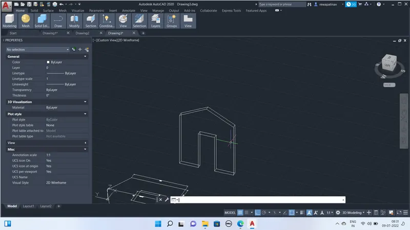
- Front of wall is 3D Rotate in YZ plane
- Sweep Command is taken and object is sweeped on the line ofa 9 inches
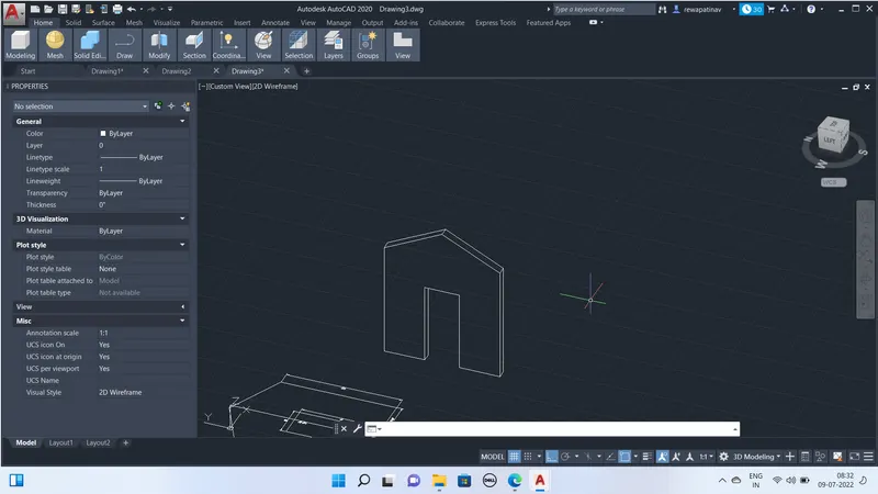
- 3D view of wall is obtained than the 3f commmand to create face a door opening
- Than HIDE Command used