Creating various 3D Models like Furniture, Footing, Girder, Column drop with panel and Gable Wall in AutoCad
Aim: To ceate a 3D furniture elements as shown in the figure:
Step by Step Procedure:
* Initially open the AutoCAD and go to 3d modelling in the setting and change the workspace to 3D modeling
* Set the Unit as Architectural (feet and inches)
* The set the limits of the drawing:
* Now choose the line command form command prompt as L
* Here i used "Absolute Co-ordinate system" and "Relative Rectangular Co-ordinate system"
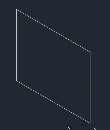
*Specify the first point :0',0',0'
* Specify the next point :@0',0',2'6"
* And specify the next point: @0',3',0'
* specify the next point: @0,0',-2'6"
* Then close the figure.
* Now covert this rectangular to a region by Using Region command in the command prompt
* Then, Choose the Extrude command
*Select the rectangle, And cursor move to the X axis direction
* Specofy the height of the Extrusion : 2'
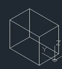
*Now change the region
* Now to choose the shaded option for 3D view by using visual style control.
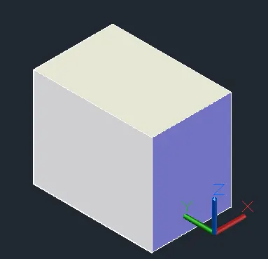
* Now choose solidedit option from command prompt
*Enter solid editing option 'Body'>'Shell'
*Select a 3D solid....remove the face .... enter the shell offeset distance :2".
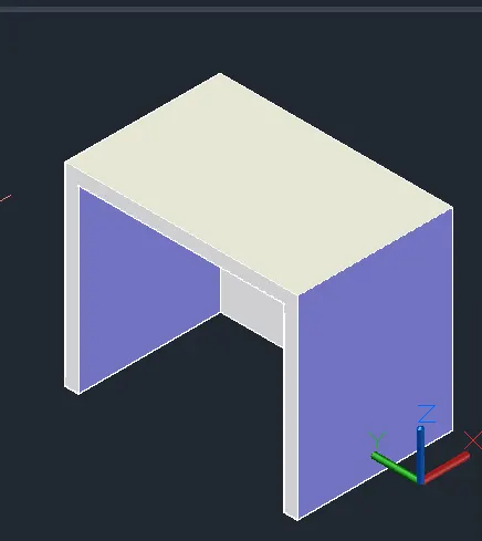
*Now create to a 2D wire frame option by using visual style control
*And select hidden option.
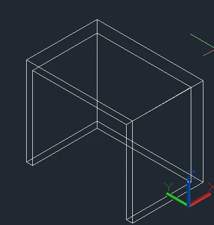
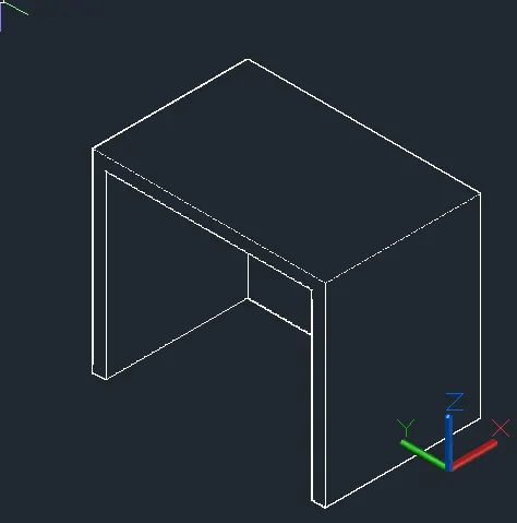
*Then again i changed the line solid colour grey for better view as shown in the fig.
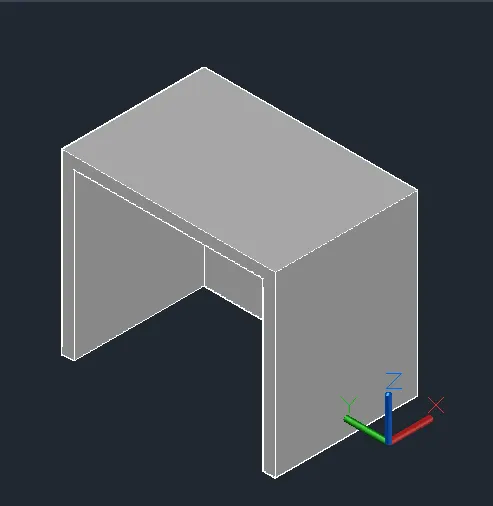
To provide the dimensions:
*Select annaotation for default style standard , FontName : txt.shx, Text height 0'4" and arrow type:Closed bank and height 0'2".
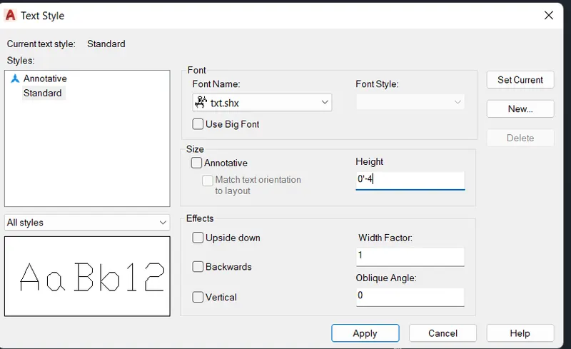
*Then choose the solidedit command for providing Dimension as isometric 3D view.
*Solidedit .... Face....
Choose the face in the solid diagram by UCS icon as using X,Y,Z DIRECTIONS.
*Chooose dimline command dimensioning is done to complete the object.
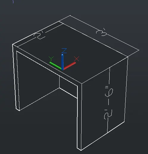
RESULT:
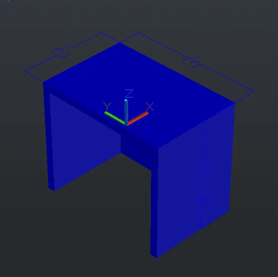
Visual style control: Shaded view.
2)AIM:
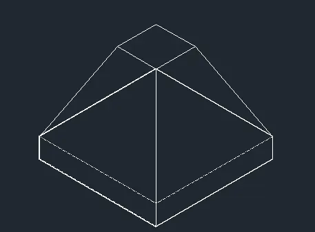
To create a 3D model of an isolated footing as shown in the above figure.
STEP BY STEP PROCEDURE:
*Initially open the autocad and go to 3D modelling in the setting and change the workspace to 3D modelling
* Set units as engineering feets and inches.
*Then set the limits of the drawings.
*Choose the rectangle command.
specify first corner point on the screen and the second @3',3'
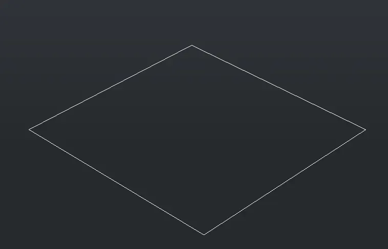
*Next choose the offset command specify the offset at a distance of 2' inside of rectangle box.
*now the size of the rectangle is 1'x1'.
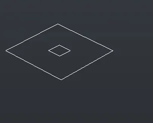
*Now choose move command to move inside rectangle object.
*Now move rectangle to z direction of 2' height.

*Now choose the line command to join the edge of the corner lineby usoing line command.
*To copy the bottom rectangle box to move up by 6".
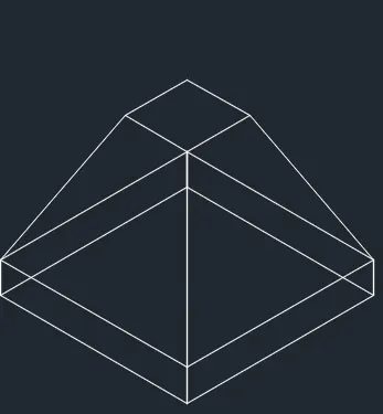
*Now select the hidden option from visual style controler.
3.Aim:
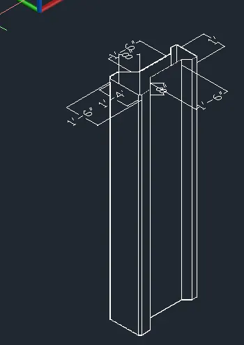
To creat the 3D view of the AASTHO type girder:
Step by Step Procedure:
Initially open the AutoCAD and goto 3d modelling in the setting and change the workspace to 3D modeling
* Set the units as Architectural (feet and inches)
* Then set the limits of the drawing:
*Now choose the Rectangle command.
*Specify first corner point @ anywhere ,Specify the other corner point @6",1'6" .
*Now choose the chamfer command Select 'Distance' Specify the first Chamfer Distance 1".
*Now select the first line and second line to drawn the Chamfer shape.
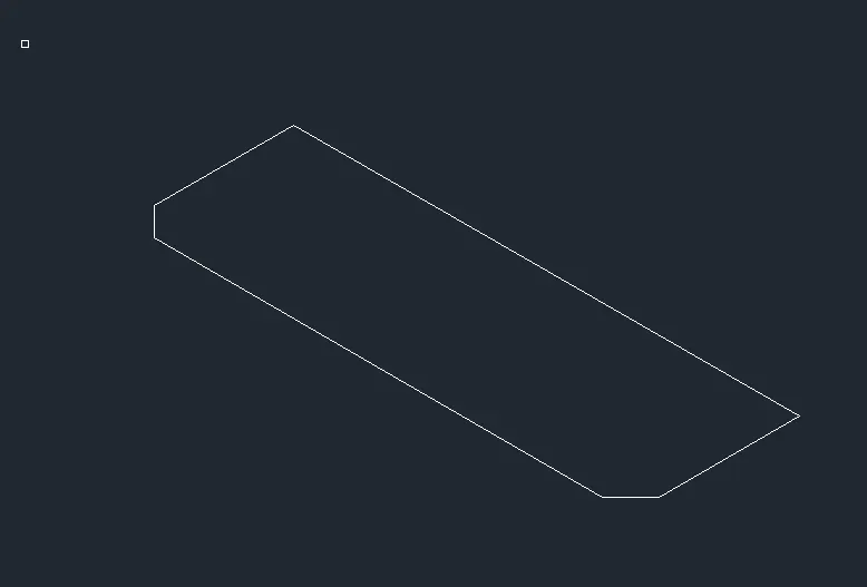
*Again choose the rectangle command, Specify the first corner point @ corner of the previous rectange Specify the other corner point @6",1'6"
*Now choose the chamfer command
*Select 'Distance'
*Specify the first Chamfer Distance:6"
*Specifuy the secont Chamfer distance :6".
* Now select the first line and second line to drawn the Chamfer shape.
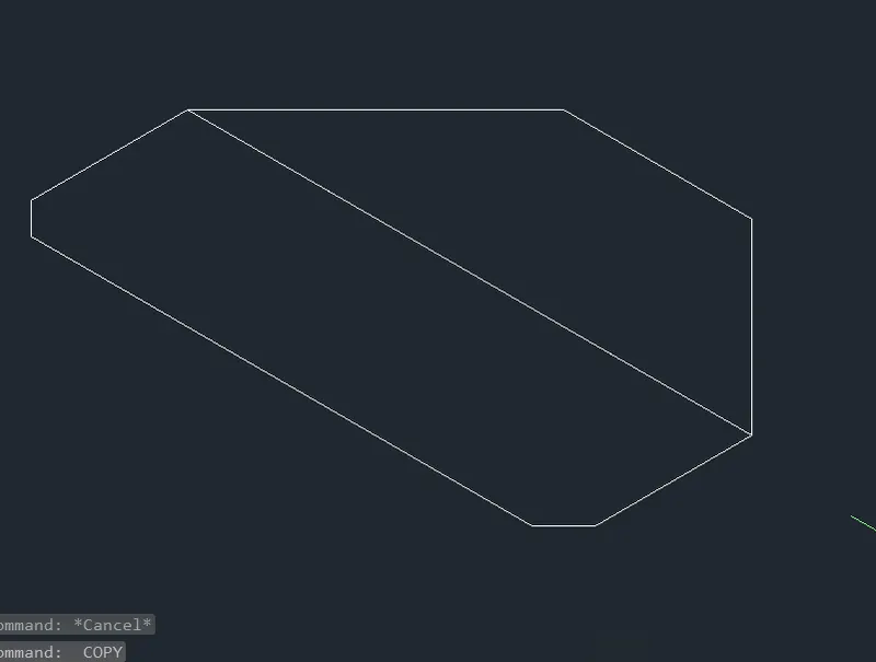
*Again choose the rectangle command Specify the First corner point @ corner of the previous rectange
*Specify the Other corner point @1'6",6"
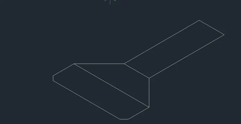
*Again choose the rectangle command
*Specify the first corner point @ corner of the previous rectange
*Specify the other corner point @6",1 then move the correct position to fixed it.
*Now choose the chamfer command
*Select 'Distance' Specify the first Chamfer Distance:3"
* Specify the secont Chamfer Distance: 3",Now select the first line and second line to drawn the Chamfer shape.
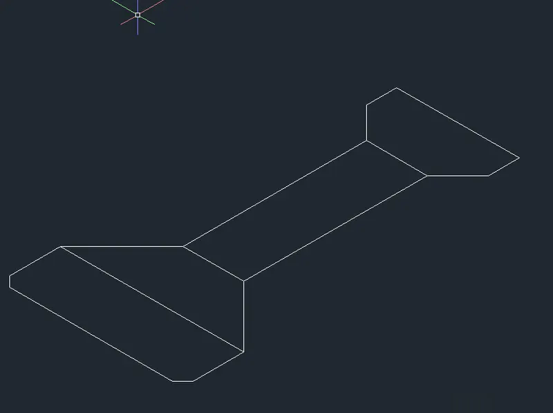
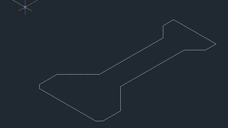
*Now Choose the EXPLODE command
*Select the hole figure the seperate the Line
*Then Erase the inside line by using Erase command like shonw in the below figure
*Now to change the Region.
*Now to select the Shade with edge option form Visual Style Controler

*Now choose the EXTRUDE command
*Select the grider, And cursor move to the y axis direction
*Specify the height of the Extrusion : 10'
*Then choose the HIDDEN option from Visual Style Controler
*Then choose the 3DORBIT command to rotate the diagrame for all Axis like given diagram
*To Provide Dimension:
*Slecet Annotation for default style Standard, FontName: txt.shx, Text height 0'4" and Arrow Type : closed blank, and Height 0'2".
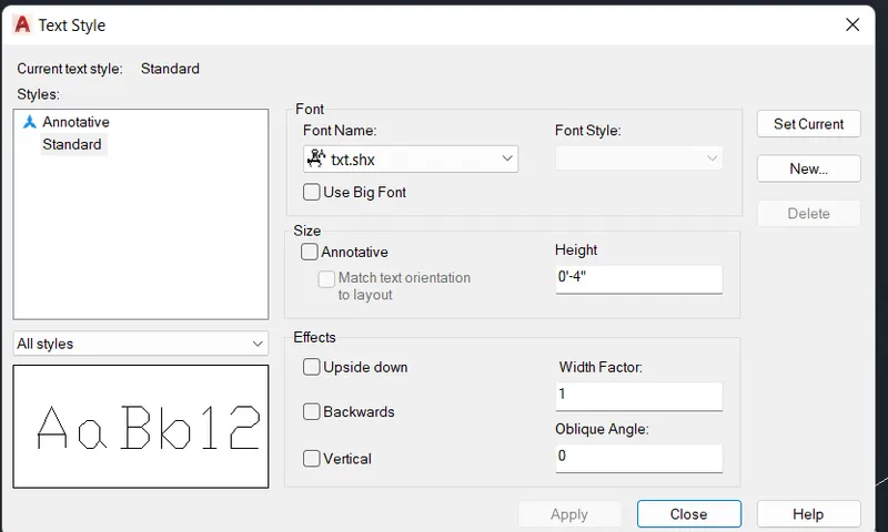
*The choose Solidedit command for providing Dimension as Isometric 3D view.
*Solidedit-->Face-->Choose the face in the solid diagram by UCS icon for using X,Y,Z direction
*Choose Dimline command dimensioning is done to complete the object.
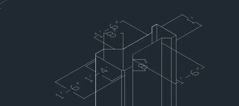
RESULT:
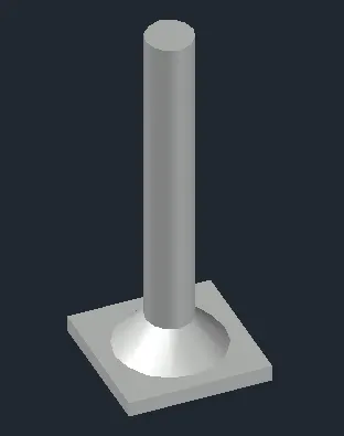
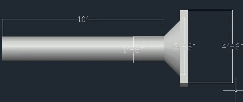
4.Aim: To creat a 3D model of a drop column with panel as shown in section and isometric view
*Step by Step Procedure:
*Initially open the AutoCAD and go to 3D modelling in the setting and change the workspace to 3D modelling.
*Now set the units as Architectural (feet and inches)
*Then set the limits of the drawing.
*Now select the rectangle command
*Specify the First corner @ anywhere
*Specify the other corner point @4'6",4'6"
*Then, Choose the Extrude command
*Select the rectangle, And cursor move to the z axis direction Specify the height of the Extrusion :6"
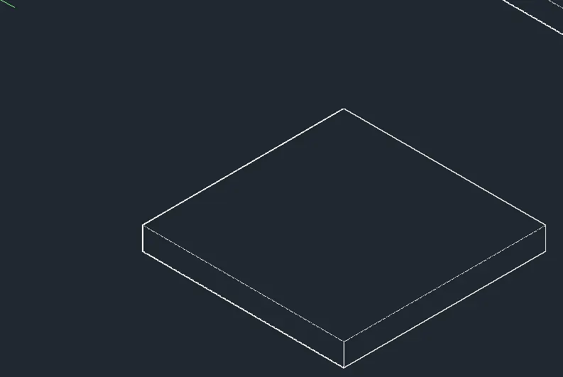
*Then To chage the Region And select the Hidden option to hide the inside line from taken Visual Style Controler
*Now Choose the SOLIDEDIT command
*To select Face option put the UCS icon in top solid box for creat the circle.
*Now choose the Circle command in Command prompt.
*Specify the center point of the circle@center of the rectangle Specify the Diameter of the circle @3'6"
*Now conver this to a region and extrude it with tapering (angle 45 degree and height 1'.
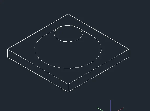
*Explode the tapered portion and the top circle is converted to a region
*Choose the Extrude comamnd
*Select the rectangle, And cursor move to the Z axis direction
* Specofy the height of the Extrusion :10'
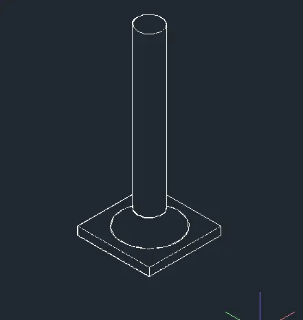
*Now to change its view to Shaded Visual Style Controller.
*Then choose the 3DORBIT command to rorate the view conveniently various 3d view.
*For better view
*To Provide Dimension:
*Slecet Annotation for default style Standard, FontName: txt.shx, Text height 0'4" and Arrow Type : closed blank, and Height 0'2".
*The choose Solidedit command for providing Dimension as Isometric 3D view.
*Solidedit-->Face-->Choose the face in the solid diagram by UCS icon for using X,Y,Z direction
*Choose Dimline command dimensioning is done to complete the object.
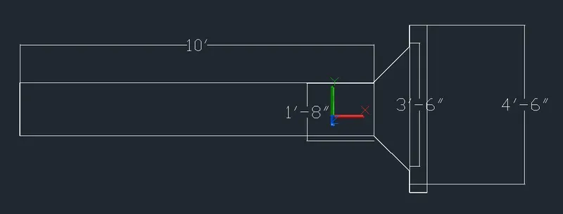
RESULT:
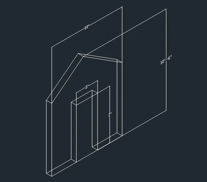
5.Aim: To ceate a 3D Model of a wall as shown in figure:
Step by Step Procedure:
*Initially open the AutoCAD and go to 3D modelling in the setting and change the workspace to 3D modelling.
*Now set the units as Architectural(feet and inches).
*Then set the limits of the drawing.
*Choose the line command.
*Specify the first point @0',0',0'
*Specify the next point @3'6",0',0'
*Specify the next point @0,0',7'
*Specify the next point @3',0,0'
*Specify the next point @0',0',-7'
*Specify the next point @ 3'6",0',0'
*Specify the next point @0',0',9'
*Specify the next point @-10,0,0'
*Specify the next point @-9',0',0'
*Draw the line 12'6"
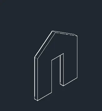
*Join the corner of the top wall of the line drawn Erase the unwanted line
*Choose the Region command
*Slect the object > select whole diagram> enter
*Now choose the EXTRUDE Command
*Now chooe the EXTRUDE Command
*select the object > select the object which is regioned
*Specify the extrude height >9"
*Enter by Extrude ut along Y-Axis direction
*The select the HIDDEN option form Visual Style Controler to hide the unwanted line
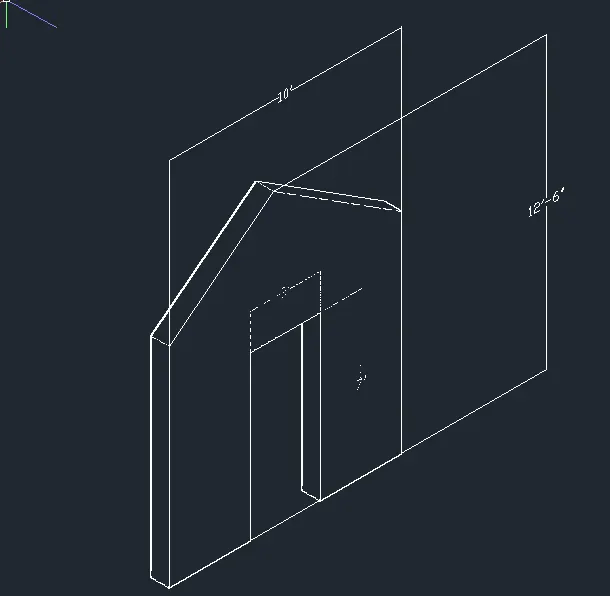
*To Provide Dimension:
*Slecet Annotation for default style Standard, FontName: txt.shx, Text height 0'4" and Arrow Type : closed blank, and Height 0'2".
*The choose Solidedit command for providing Dimension as Isometric 3D view.
*Solidedit-->Face-->Choose the face in the solid diagram by UCS icon for using X,Y,Z direction
*Choose Dimline command dimensioning is done to complete the object.
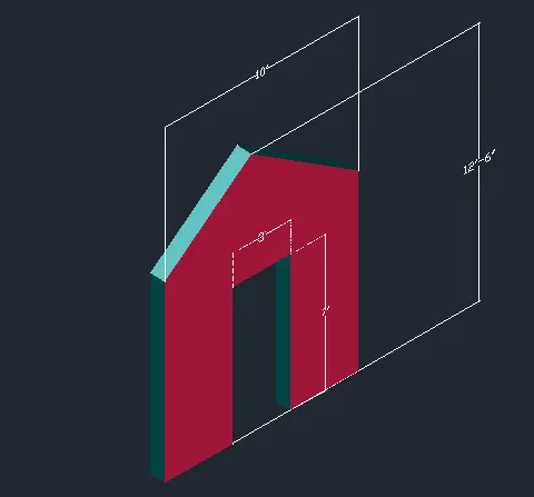
*Now choose the Colour Face option to provide the wall colour
*Select the colour face option from->Home -->Solid Editing --> Extrude Face--> Colour Face
*Now select the solid face in Diagram, Dialouge box appear on display
*Intex colour --> AutoCAD ColourIndex(ACI), Colour :240
*Similarly hidden inside wall colour also provided.
RESULT: