Creating various 3D Models like Furniture, Footing, Girder, Column drop with panel and Gable Wall in AutoCad
1)AIM:
Create a 3D Furniture element as shown in the Figure. Assume dimensions which are missing.
PROCEDURE:
Set the units to engineering,precision 0'-0" & scales to inches
Using line command create a rectangle of length 3' & width 2'6" & height 2'6"
As per given dimension create the furniture using line command
Mention the dimensions using UCS command
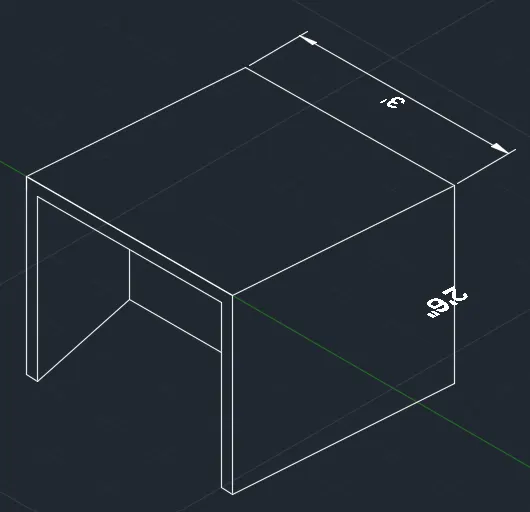
RESULT:
2)AIM:
Create the 3d Model of an Isolated footing as shown in Figure.
PROCEDURE:
Set the units to engineering,precision 0'-0" & scales to inches
Create a rectangle of 2'*2' & another rectangle of 1'*1' on the top view
with the move command move the small rectangle by 2' in z direction
Click on the loft from home tool bar & select 2 rectangles to loft
Click on the larger rectabgle 7 extrude ta a height of 6"
Mention the dimensions using UCS command
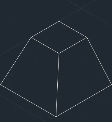
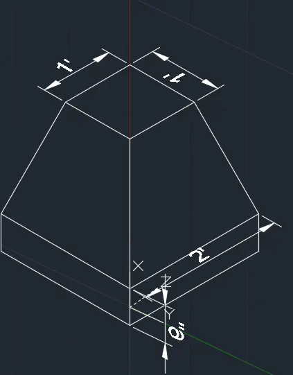
RESULT:
3)AIM:
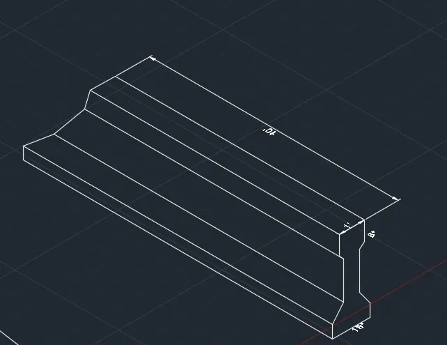
Create the 3D view of the AASTHO Type Girder
PROCEDURE:
Set the units to engineering,precision 0'-0" & scales to inches
Using line command create the web & flange to the given dimension
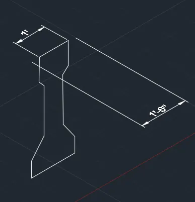
With the 3dorbit command turn the view & draw of 10' in z axis
Draw the lines as per given dimension
Mention the dimensions using UCS command
RESULT:
4)AIM:
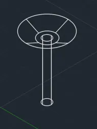
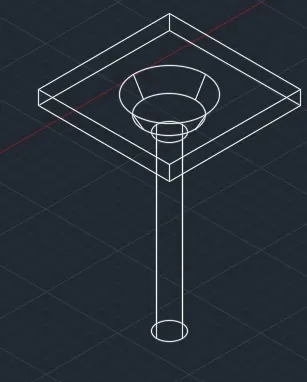
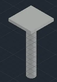
Create a 3d Model of a drop column with panel as shown in section and isometric view.
PROCEDURE:
Set the units to engineering,precision 0'-0" & scales to inches
Create a circle to a dia of 1'6" create a region & extrude it to a distance of 10'
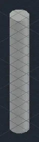
Using cone command create a cone & base dia 1'6"
Click on the top radius 1'6" & height 1"

Place the frustum to the top of the created circle
Create a recatangle of dimension 4'6"*4'6" & extrude it to a height of 6"
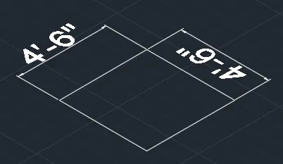
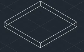
Place the recatangle to the centre of the cone
RESULT:
5)AIM:
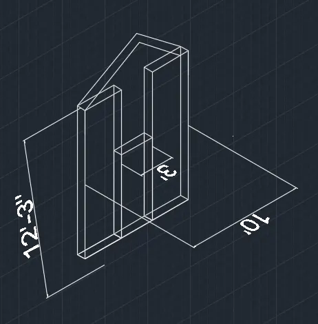
Create the 3d model of a wall as shown in Figure. Consider wall thickness as 9”.
PROCEDURE:
Set the units to engineering,precision 0'-0" & scales to inches
Create a rectangle of dimension 10'*9" ,from the line centre create an offset of 1.5" on bothb sides.

Using command BO create a region & extrude to a height of 12'6"
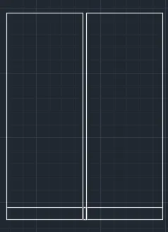
Turn on the hidden mode extrude the rcetangle of dimension 3'*9" to a height of 7'
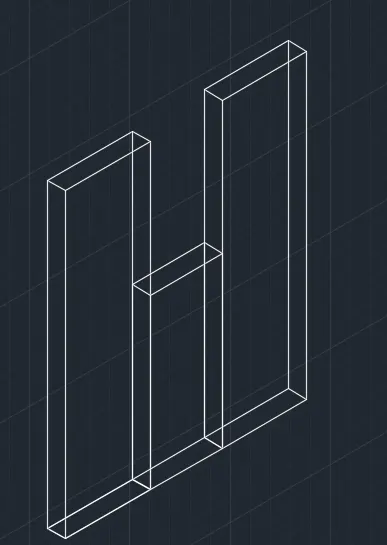
Create a vertical line from the centre ,draw a horizontal line ,create a slanding line connecting towards horizontal line
Mention the dimensions using UCS command
RESULT: