Creating various 3D Models like Furniture, Footing, Girder, Column drop with panel and Gable Wall in AutoCad
CREATING VARIOUS 3D MODELS LIKE FURNITURE, FOOTING, GIRDER, COLUMN DROP WITH PANEL AND GABLE WALL IN AUTOCAD
Introduction
A process of creating a mathematical representation of any surface of an object in three dimensions by using special software is called 3D modeling.
- Benefits of 3D modelling:
- Using 3D models, users can get a more evocative design and they can even see the virtual image of their projects.
- An architectural 3D model is much more interesting and realistic than a 2D model.
- The experience that a 3D model gives is much more compelling and satisfying to the user than viewing a 2D drawing.
- 3D models are an amazing advantage to interior designers as they get to create and then modify 3D interior as well as exterior as per their need and choice.
- In a 3D design, the user gets to know the physical dimensions of the objects and its distance in relation with other objects in the total layout.This feature helps to see and modify arrangements of objects based on their sizes.
- Various AutoCAD 3D commands include:
- Extrude:
- Draw--> Modelling--> Extrude.
- This command allows to create a 3D object by extruding a 2D face along a line or path.
- For eg: A cylinder can be created by selecting a 2D circle and extruding it along with the a path.
- Sweep:
- Draw--> Modelling--> Sweep.
- This command helps the user to extrude the 2D objects without the 2D face being orthogonal to the beginning of the path.
- Union:
- Modify--> Solids editing--> Union.
- This command allows to combine two objects converting into one single object.
- Subtract:
- Modify--> Solids editing--> Subtract.
- This commaand is oppposite to union command.
- This command woks when there is a common area in both the objects.
- Intersect:
- Modify--> Solids editing--> Intersect.
- This command retains only the area that is common to both the objects.
1.
Aim
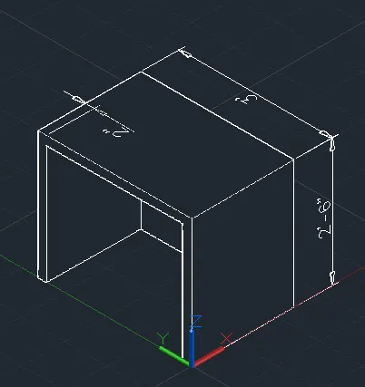
To create a 3D furniture element as shown in the figure:
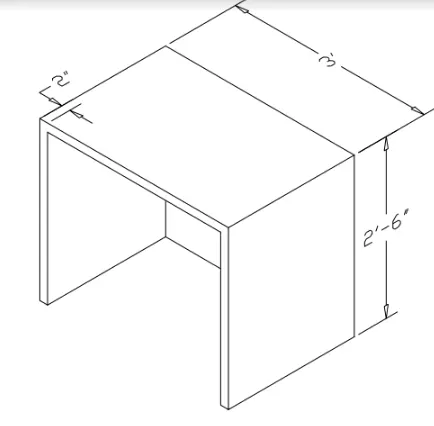
Procedure:
- Initially open the AutoCAD and go to 3D modelling in the settings and change the wokspace to 3D modelling.
- Now set the units as Architectural (feet and inches).
- Then set the limits of the drawing:
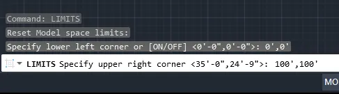
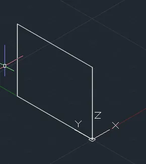
- Now, using line command draw the box structure:
- Specify the first point : 0',0',0'
- Specify the next point: @0',0',2'6"
- Specify the next point: @0',3',0'
- Specify the next point: @0',0',-2'6"
- Then close it.
- Now, convert this rectange to a region by typing region in the command prompt.
- Then, extrude this rectangle at a height of 2'.
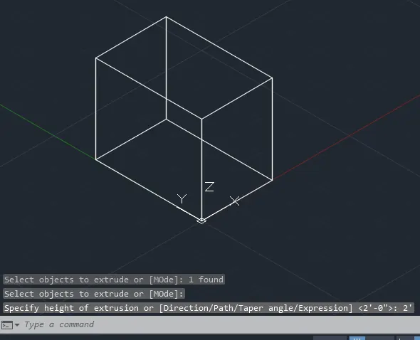
- Now again choose line command and draw the inner rectangle.
- Convert this rectangle to region and then extrude it at a height of 1'10".
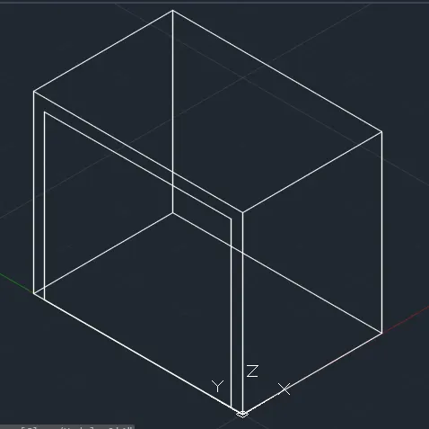
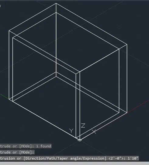
- Now, using the subtract command, subtract the inner rectangle from the outer rectangle.
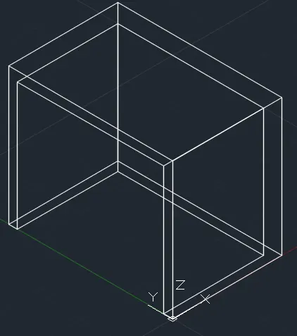
- Now, make it hidden.

- Now, using dimlin command dimensioning is done to complete the object.
2.
Aim:
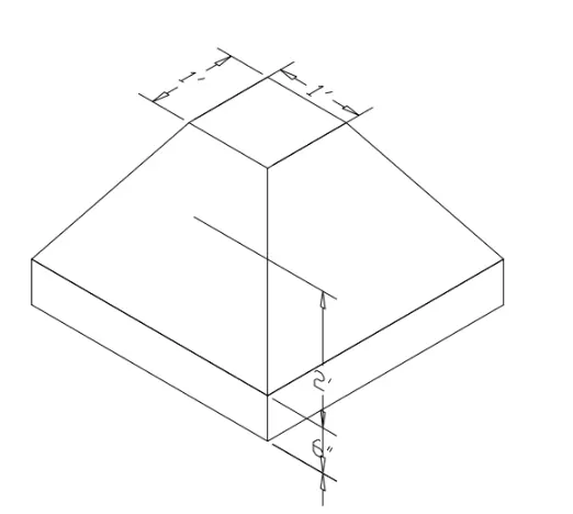
To create the 3D model of an isolated footing as shown below:
Procedure:
- Initially open the AutoCAD and go to 3D modelling in the settings and change the wokspace to 3D modelling.
- Now set the units as Architectural (feet and inches).
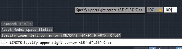
- Then set the limits of the drawing:
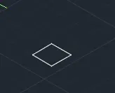
- Choose the line command and draw a square of side 1'.
- Then, convert it into a region and then extrude it downwards at a depth of 2' with tapering angle of 45 degrees.
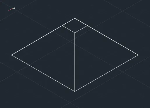
- Now again choose line command and draw a rectangle at the bottom of the tapered section and then convert it to a region.
- Then extrude the rectangle downwards at a depth of 6".
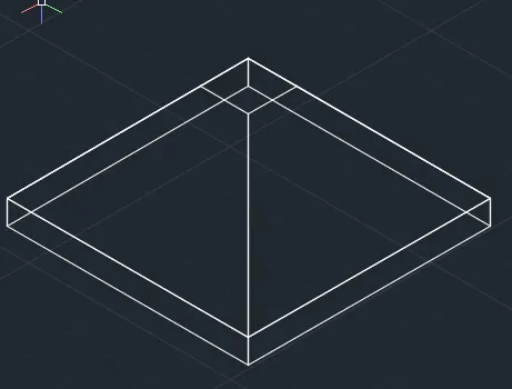
- Now, make it hidden.
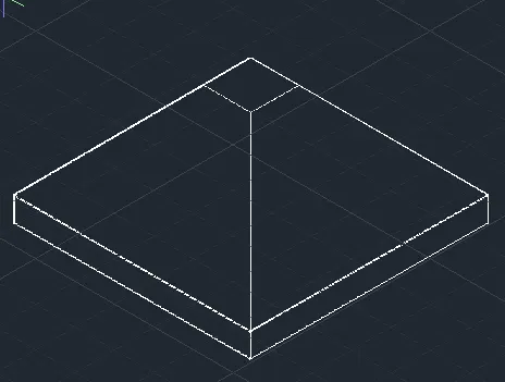
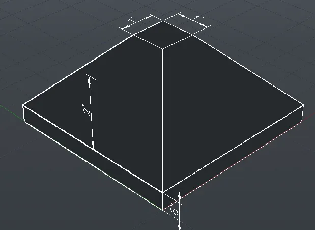
- Now dimension it using dimlin command. For this, place the UCS origin tool to the surface where we have to provide dimension.
3.
Aim:
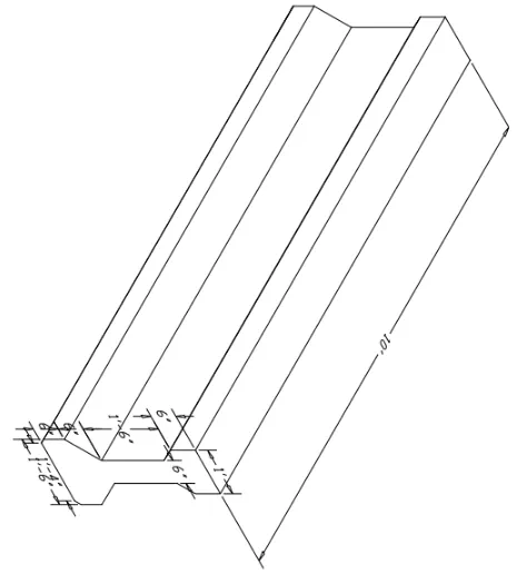
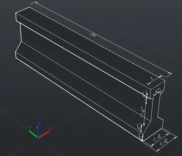
To create the 3D view of the AASTHO type girder:
Procedure:
- Initially open the AutoCAD and go to 3D modelling in the settings and change the wokspace to 3D modelling.
- Now set the units as Architectural (feet and inches).
- Then set the limits of the drawing:
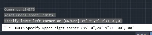
- Now using the line command drawn an I section as given in the question:
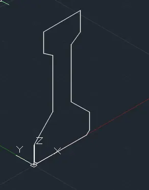
- Now, convert this figure to a region so that it can be extruded.
- Then the figure is extruded at height of 10'.
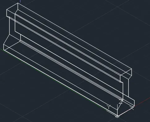
- Now, make the visibility to hidden.
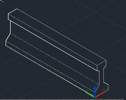
- With help of UCS coordinates do the dimensioning.
4.
Aim:
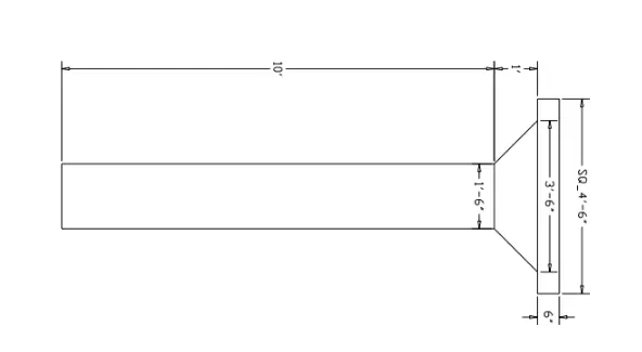
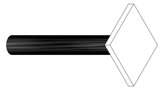
To create a 3D model of a drop column with panel as shown in the section and isometric view:
Procedure:
- Initially open the AutoCAD and go to 3D modelling in the settings and change the wokspace to 3D modelling.
- Now set the units as Architectural (feet and inches).
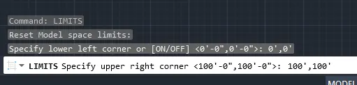
- Then set the limits of the drawing:
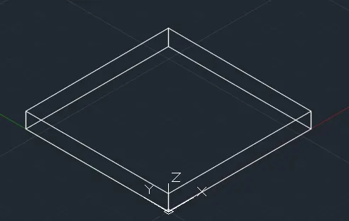
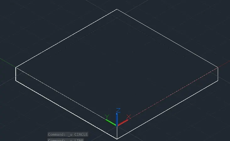
- Initially in the 3D modelling window, a square having side of 4'6" is constructed in the SW view.
- It is then converted to a region and is extruded at an extrusion height of 6".
- Then it is changed to hidden.
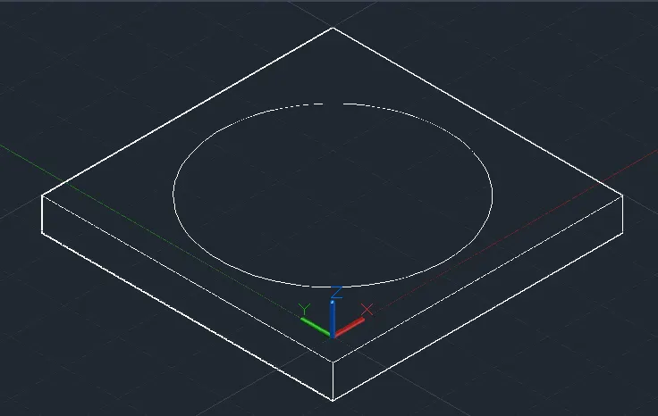
- Now, at the centre, a circle is created having a diameter of 3'6".
- For this, place the UCS coordinte on the top surface where we need to work.
- Now, convert this to a region and extrude it with tapering ( angle 45 degrees and height 1').
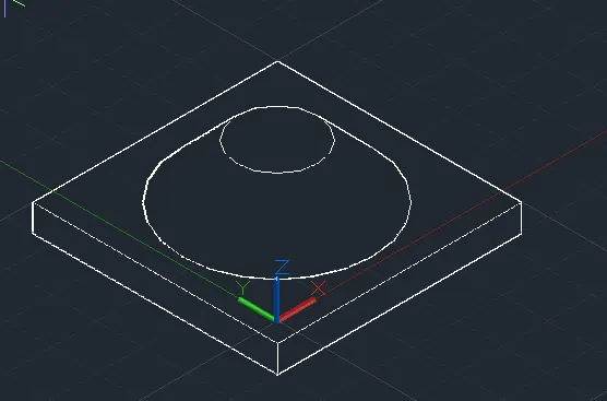
- Explode the tapered portion and the top circle is converted to a region and is then extruded at an extrusion height of 10'.
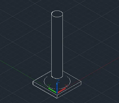
- Now, change its view to shaded.
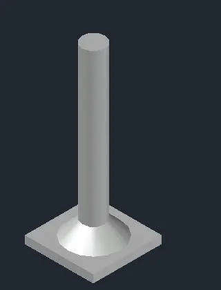
- Now, in the command prompt type 3D orbit and change its view conveniently.
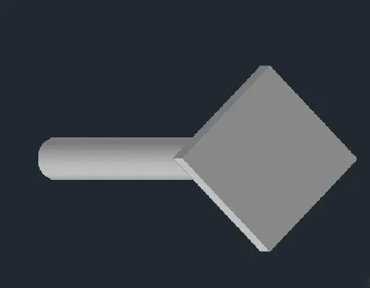
- Now, change the view to right and do the dimensioning.
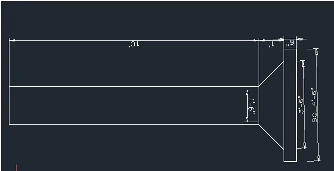
- Hence, completed.
5.
Aim:
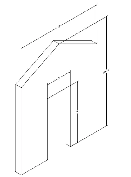
To create 3D model of a wall as shown in figure:
Procedure:
- Initially open the AutoCAD and go to 3D modelling in the settings and change the wokspace to 3D modelling.
- Now set the units as Architectural (feet and inches).
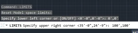
- Then set the limits of the drawing:
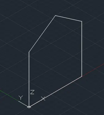
- Now, choose line command and make the workspace to SW direction and draw the outline of wall (by distance method).
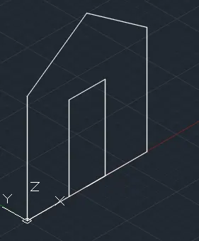
- Now, using line command create the door of the wall.
- For this initially mark the centre of the bottom line and take 1'6" to both sides and draw upto height of 7'.
- Now, convert this to region and extrude it backward at a distance of 9" which marks the wall thickness.
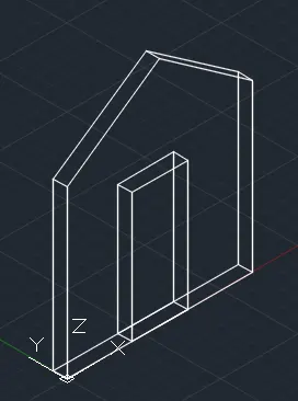
- Now, subtract the door portion from the wall using subtract command.
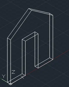
- Now, make the view hidden.
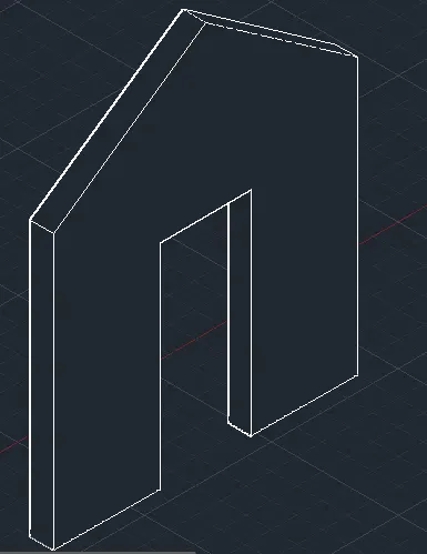
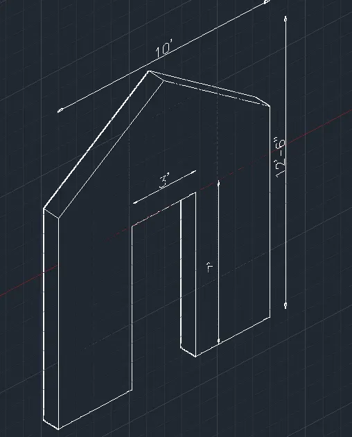
- Now, dimensioning is done with the help of UCS origin option.
Result:
The various 3D models have been created as follows:
1. 3D furniture element is created as given below:
2. 3D model of an isolated footing is created as given below:
3. 3D view of an AASTHO type girder is created as given below:
4. 3D model of a drop column with panel is created as given below:
- Section:
- Isometric view:
5. 3D model of a gable wall is created as shown below: