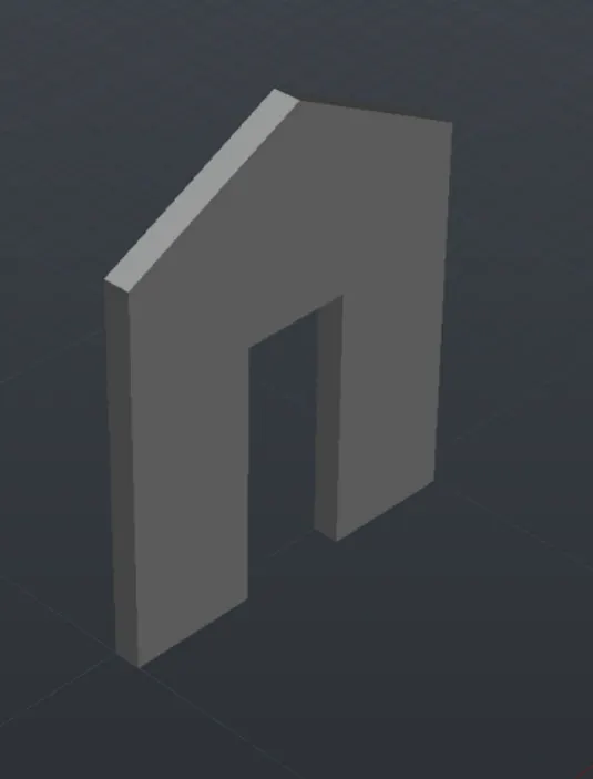
Creating various 3D Models like Furniture, Footing, Girder, Column drop with panel and Gable Wall in AutoCad
QUE 1]
AIM -
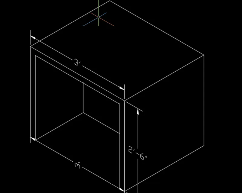
To create a 3D furniture element As given in the figure and tourism dimension which is missing in the drawing
INTRODUCTION
the three-dimensional furniture element was drawn in the AutoCAD using the different tools in AutoCAD 3D models are widely used anywhere in 3D graphics and CAD their use predates the widespread use of 3D graphics on personal computers the 3D model are mainly preferable in civil engineering and when we design a building in the AutoCAD than creating 3D
COMMAND USED
line command
rectangle command
dimlinearcommand
region command
extrude command
subtract command
Unit command
Diastyle command
3D face command
3D Orbit command
head command
explode command
Move command
copy command
list command
PROCEDURE -
STEP 1
First, we have to open the AutoCAD and need to set the unit and diastyle
.next we have to enter the UCS command and adjust the ucs icon on the screen
after setting the ucs on the screen we need to draw the line with the length 3'
next draw the line from the previous line upwards
with the length of 2'6".
again draw the line from the previous line with the length of 3' horizontally.
next to draw the line from the first line and last line to close the rectangle next we have to use the extrude command to extrude the rectangle towards back with a length of two
- STEP 2
next, we draw the rectangle inside the extruded box as shown in the figure
next we have to extrude the inside rectangle with the length of one tail as shown in the below figure
next we have to use the 3D face command to hide the inner part and also use had come on to hide them as shown in the below figure
next, we put the dimension for every part in the drawing using the dim linear command as shown in the below figure
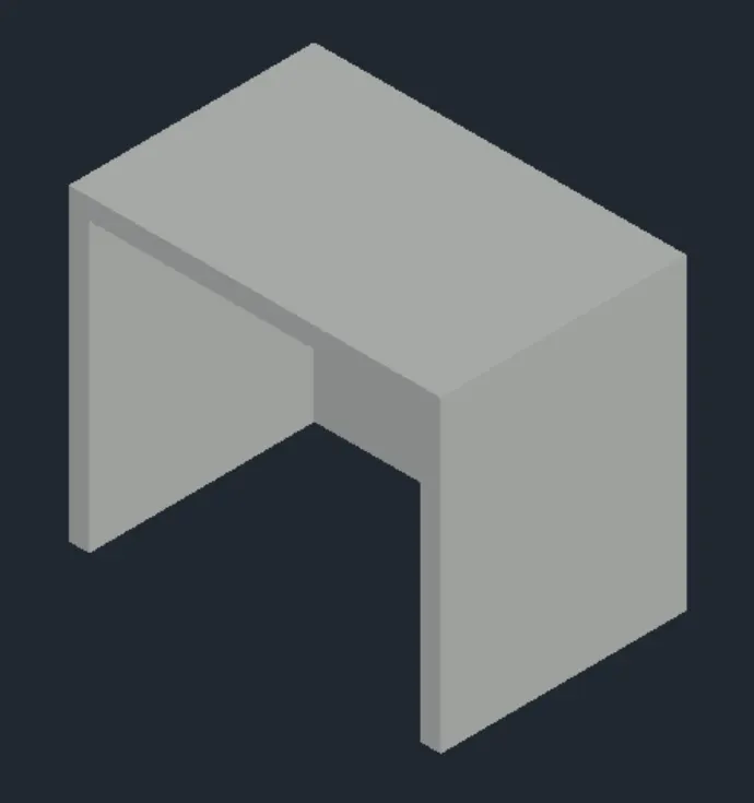
next week leave the custom visual styles at the top left corner of the drawing screen and select the shaded option in the custom visual style
RESULT
QUE 2 ]
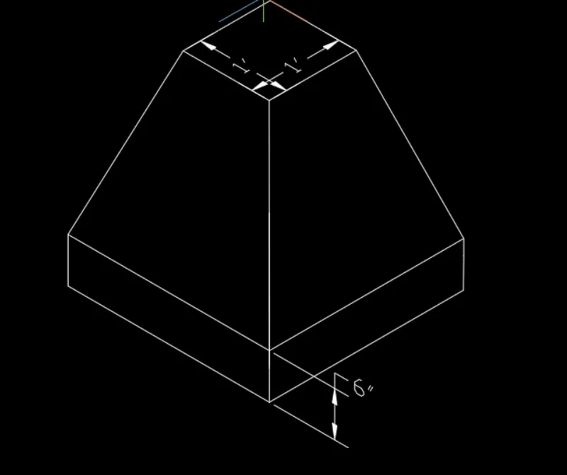
AIM ] Create the 3d Model of an Isolated footing as shown in Figure.
INTRODUCTION
the three-dimensional furniture element was drawn in the AutoCAD using the different tools in AutoCad 3D models are widely used anywhere in 3D graphics and CAD their use predates the widespread use of 3D graphics on personal computers the 3D model are mainly preferable in civil engineering and when we design a building in the AutoCAD than creating 3D
COMMAND USED
line command
rectangle command
dimlinearcommand
region command
extrude command
subtract command
Unit command
Diastyle command
3D face command
3D Orbit command
head command
explode command
Move command
copy command
list command
PROCEDURE -
Step 1
we have to open the AutoCAD and set the units using the units command next.
select the dim style command and select a primary unit as architectural.
next, we use the ucs command to set the direction of the x-axis y-axis and Z-Axis.
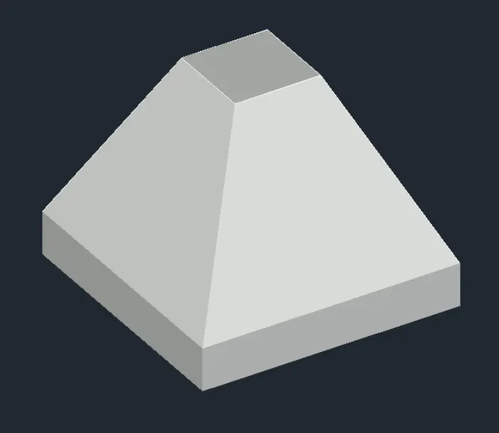
next, we draw a rectangle using the line combined with the size of 3 X3.
next to use extrude command to extrude the rectangle upwards with the length of 6'.
next again we draw another rectangular at the center of the outer rectangle
Step 2 next we use the more command to the more in a rectangle upwards with the length of 2'
Step 3 next to use the rulesurf command to join the four corners of the Moved rectangle and four corners of extruded rectangle to co-ordinate Each Other
step 4 next to in need to use 3D face command to visible as a 3D model as shown in the figure next we use the head command and press enter then we use the select the four corners of every part in the drawing after selecting the four corners of every part in the drawing and then press enter the line visible in the path after pressing the enter
step 5 next to we need to put the dimension for every part in the drawing as shown in the below figure
step 6 when we click the custom visual style at the top left corner owner of the drawing screen the select the shaded option in the custom visual style
RESULT-
QUE 3 ]
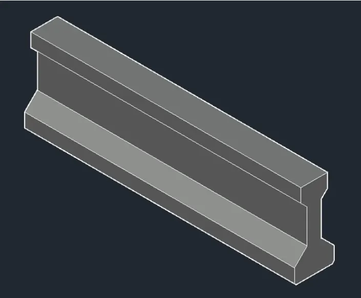
AIM ] Create the 3D view of the AASTHO Type Girder
INTRODUCTION
the three-dimensional furniture element was drawn in the AutoCAD using the different tools in AutoCAD 3D models are widely used anywhere in 3D graphics and CAD their use predates the widespread use of 3D graphics on personal computers the 3D model are mainly preferable in civil engineering and when we design a building in the AutoCAD than creating 3D
COMMAND USED
line command
rectangle command
dimlinearcommand
region command
extrude command
subtract command
Unit command
Diastyle command
3D face command
3D Orbit command
head command
explode command
Move command
copy command
list command
PROCEDURE -
Step 1
first we have to open the AutoCAD and set the units using the units command .
next to we use the UCS command to set the direction of the x-axis and y-axis and Z-Axis.
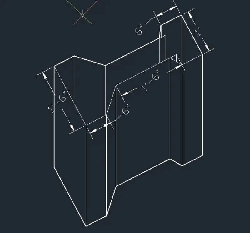
next we have to draw the horizontal line with the length of 1'4 ".
next to have to draw the incline decline from the previous line next from the previous line we have to draw the another vertically upwards with the length of 6".
next again we have to draw the line from the previous line with the angle of 135 degree with the length of 8".
draw the vertical line from the previous line with the length of 1'3".
next to withdraw the another land from the previous line with the angle 45 degree with the length of 4'5 "vertical line from the previous line with the length of 6'8".
next to use the mirror command and press enter then select the right portion and place a cursor at the middle of the first line then automatically right side portion will be mirrored in the opposite side as shown in the below figure
RESULT-
QUE 4 ]
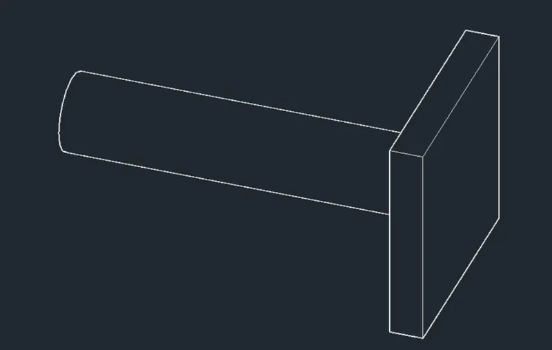
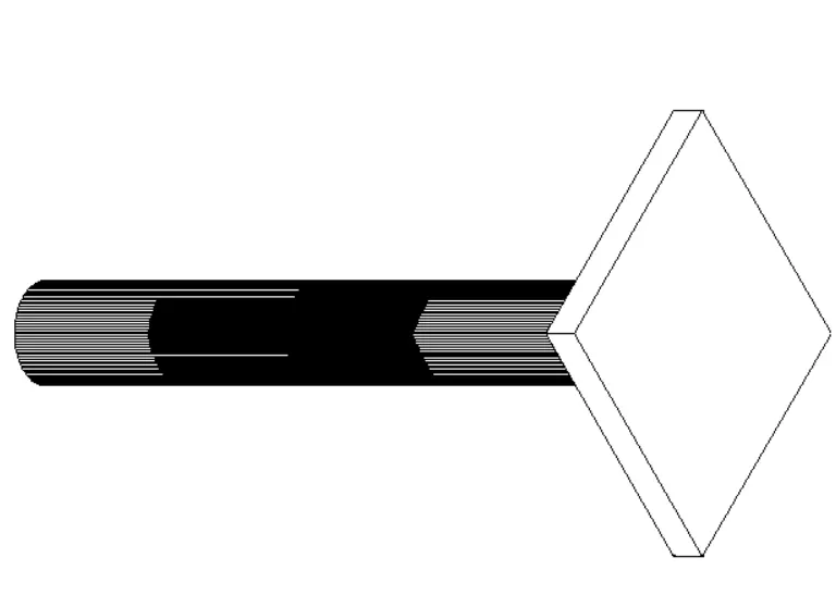
AIM ] Create a 3d Model of a drop column with panel as shown in section and isometric view.
INTRODUCTION
the three-dimensional furniture element was drawn in the AutoCAD using the different tools in AutoCad 3D models are widely used anywhere in 3D graphics and CAD their use predates the widespread use of 3D graphics on personal computers the 3D model are mainly preferable in civil engineering and when we design a building in the AutoCAD than creating 3D
COMMAND USED
line command
rectangle command
dimlinearcommand
region command
extrude command
subtract command
Unit command
Diastyle command
3D face command
3D Orbit command
head command
explode command
Move command
copy command
list command
PROCEDURE -
Step 1
First we have to open the AutoCAD and set the units using the units command .
next we use the ucs command to set the direction of x axis y axis and Z Axis .
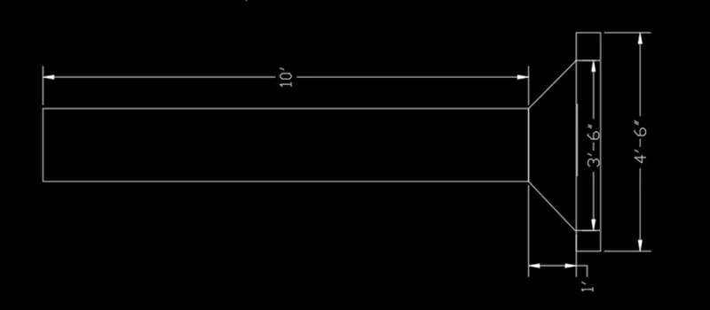
next how to draw the line with the length of 10'.
next we have to draw the another line from the previous line with the angle 45 and with the length of one.
next we draw the straight line from the previous line with the length of 6 ".
next we draw the another line downwards from the previous line with the length of 4'6 ".
next select the upper portion of the figure and the use mirror command to Mirror to the opposite side .
Next we draw the remaining side of the drawings as shown in the below figure
Step 2
next we rotate the Drop column in the different view using 3D Orbit command as shown below figure
Step 3 next we click the custom visual side at the top left corner of the drawing screen and select the shaded portion in the custom visual style
RESULT -
QUE 5 ]
AIM -
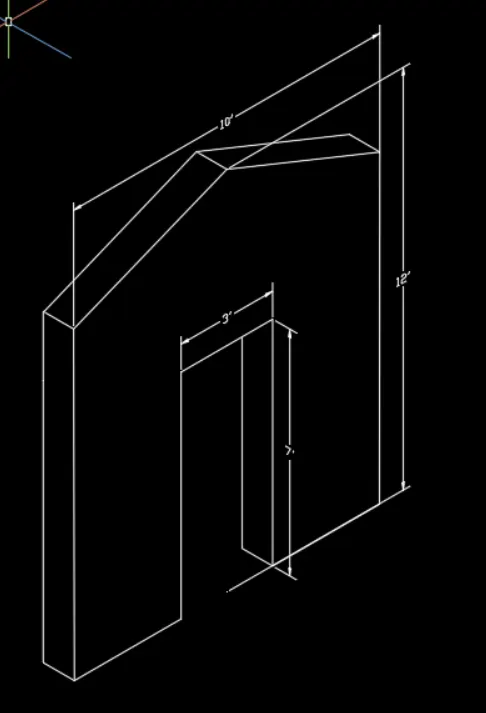
Create the 3d model of a wall as shown in Figure. Consider wall thickness as 9”.
INTRODUCTION
the three-dimensional furniture element was drawn in the AutoCAD using the different tools in AutoCad 3D models are widely used anywhere in 3D graphics and CAD their use predates the widespread use of 3D graphics on personal computers the 3D model are mainly preferable in civil engineering and when we design a building in the AutoCAD than creating 3D
COMMAND USED
line command
rectangle command
dimlinearcommand
region command
extrude command
subtract command
Unit command
Diastyle command
3D face command
3D Orbit command
head command
explode command
Move command
copy command
list command
PROCEDURE -
STEP 1
First to how to open the AutoCAD and set the units using the units command
next we use the ucs command to set the direction of x axis y axis and Z Axis
next we need to draw horizontal forward with length of 10'
next we draw the another line vertically upward with a length of 10'.
next to draw the line from the previous line with the angle of 125 degree.
Again from the previous line we draw the another line with the angle of 225 degree and length the five.
Next join the line from the first line to last line as shown below figure
Step2 Next again we draw the rectangle inside the wall as shown in the figure.
next to use the extrude command to extrude the wall with the thickness of 9'
next again we use extrude command to extrude inside rectangle with the thickness of 9".
Step 3 we subtract the door part of from the values in the substrate to command next to have to use the 3D face command to hide the inner part and also use hide command to hide them
Trip for next week click the custom visual style at the top left corner of the drawing screen and select the shaded option in the custom visual style
Step 4
Next we click the custom visual style at the top left corner of the drawing screen and select the shaded option in the custom visual style
RESULT -