Creating Levels, Grids, Layout and model elements for a residential unit using REVIT
1. AIM: To define BIM and explain about features of BIM and benefits of using BIM over 2D CAD tools.
BIM DEFINITION: BUILDING INFORMATION MODELLING.
It is a concept that was created by autodesk.Autodesk Revit is a software or modelling tool
that helps us in achieving BIM as a process.
EXPLAINATION OF BIM FEATURES AND ITS BENFITS OVER 2D CAD TOOLS:
There are two features in BIM.They are A.COORDINATION B. COMPUTATION.
A.COORDINATION: Autodesk Revit helps us in achieving coordination between multiple disciplines.Revit offers us in helping coordination across projects between architects,structural engineers,mechanical engineers.All these engineers can work on a single project at a time.
B.COMPUTATION: Revit as a BIM tool helps us in performing computation such as material schedule, quantity schedule or to perform the energy analysis or there are different tools associated in autodesk revit.For example in structural discipline there is robo structural analysis tool that helps us in computing the response to the loads applied to the buildings.
BENEFITS OVER 2D CAD TOOLS: In revit if i make any changes in floor plan then automatically these changes will be reflected in elevation and section also but in 2D CAD if i make a change in floor plan then i should seperately make changes in both elevation and section.
2. AIM: To understand the concept of Categories,families,elements in Revit and choose a Category from INSERT tab,pick a family and element and understand the instances and insert it to a REVIT Model.
PROCEDURE TO INSERT A FAMILY OR ELEMENT TO A REVIT MODEL:
Go to ARCHITECTURE TAB
Click on DOOR tool
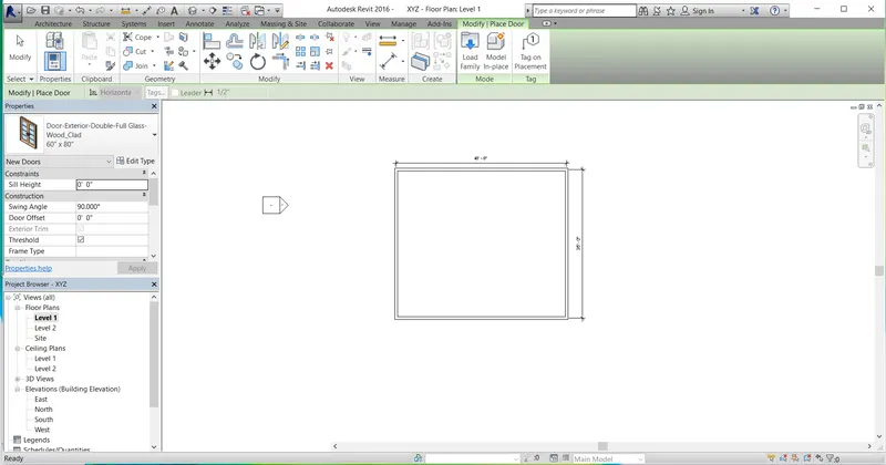
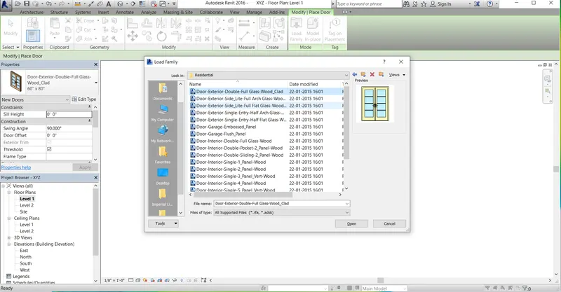
Click on Load Family tool
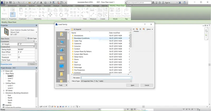
Now Categories will be displayed , select Doors category
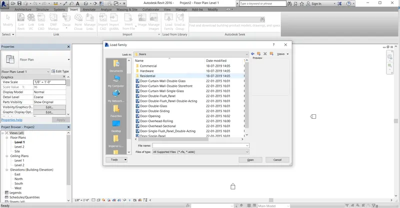
Now Families will be displayed, select Residential family
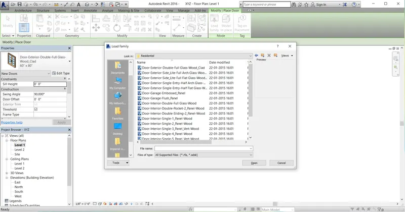
Now Elements will be displayed, select Door exterior double full glass element
click on Open button
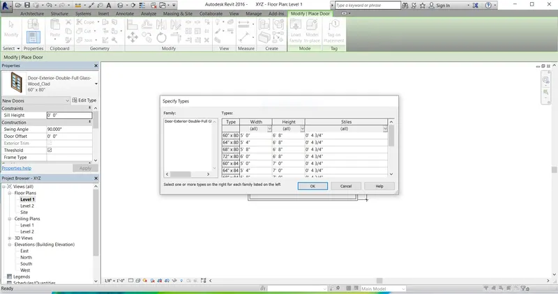
Click on OK button
Now Place a Door in REVIT model
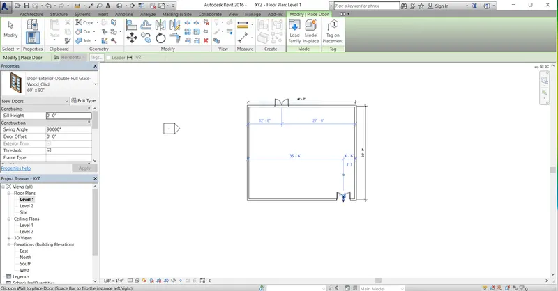
Door element is finally placed in a revit model.
3. AIM: To open a new project and saving the file with appropiate name.Setting the project units to Imperial/Metric and completing the project information using Manage tab and setting up the maximum backups for the current project file to 3.
PROCEDURE TO OPEN A FILE WITH ARCHITECTURAL TEMPLATE AND SAVING THE FILE WITH A NAME:
Click on NEW option
select architectural template
click on project
press OK button
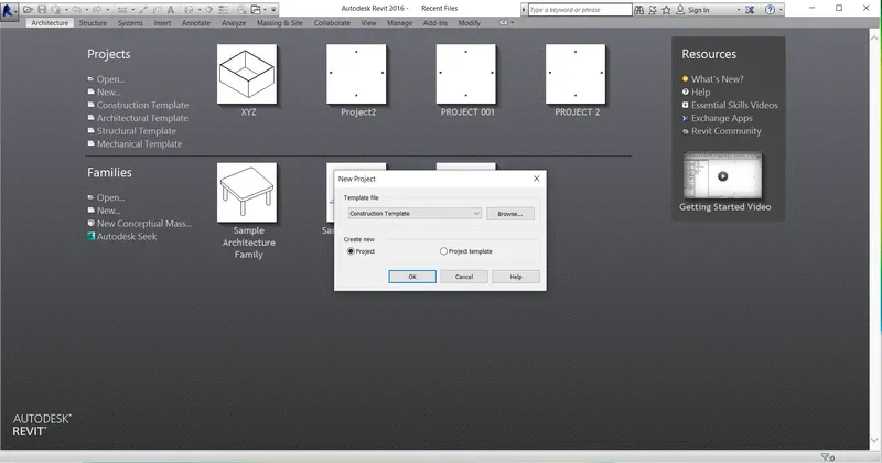
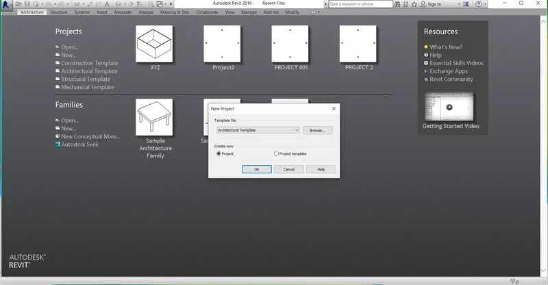
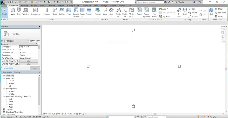
Now click on FILE button
click on SAVE
Give a name to the file like ABC Project
click on SAVE button
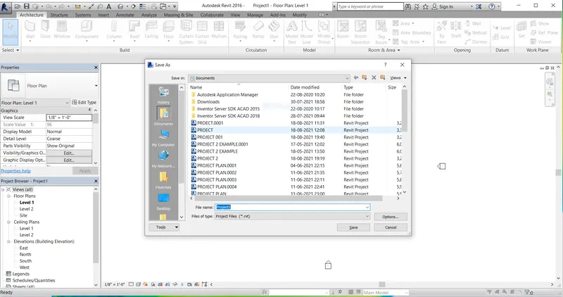
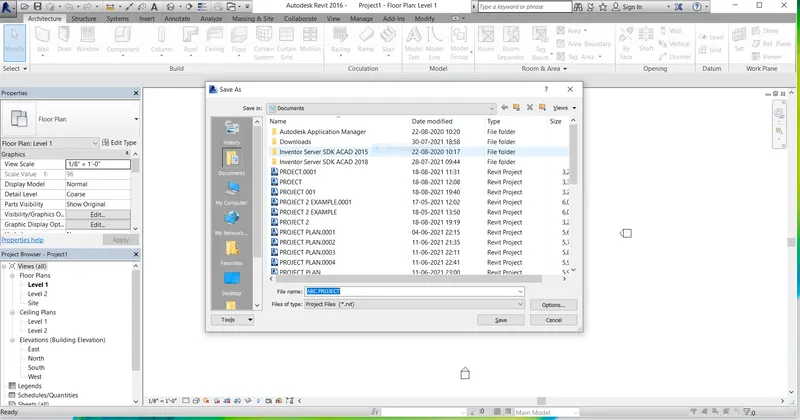
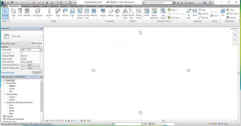
PROCEDURE TO COMPLETE THE PROJECT INFORMATION BY USING MANAGE TAB:
Go to MANAGE tab
click on Project Information tool
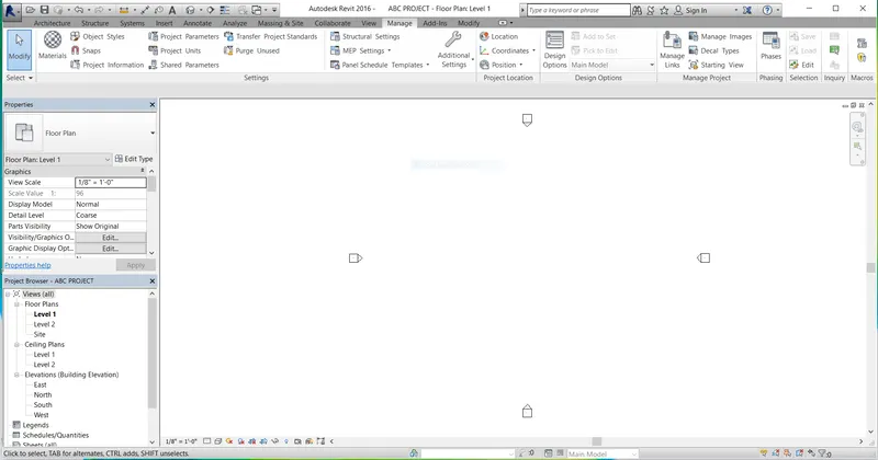
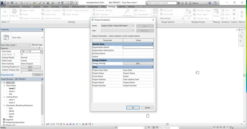
Now fill the Project Information details
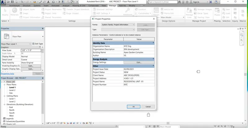
Now press OK button
PROCEDURE TO SET UP THE MAXIMUM BACKUPS FOR CURRENT PROJECT TO 3:
Go to FILE tab
Click on SAVE AS
select Project option
Click on OPTIONS option
Give number of backups to 3
Then press OK button
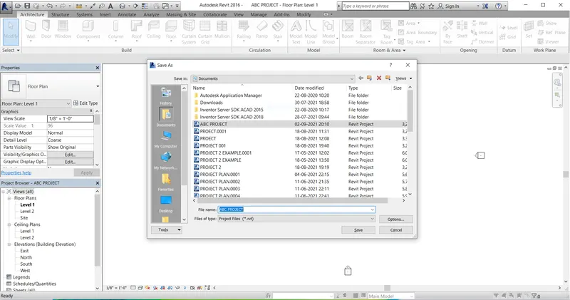
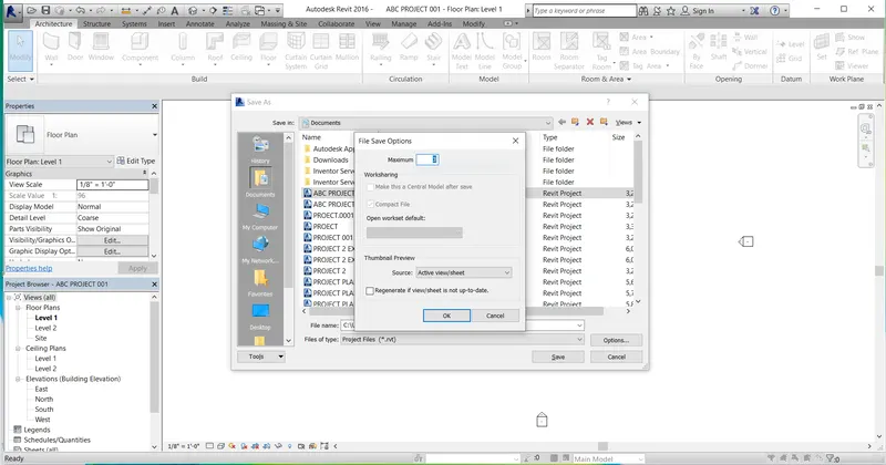
Now finally 3 backup files to the current project name ABC PROJECT has been created.
4.AIM(1): To understand the concept of levels and to create the following levels: Ground Floor @ 0', First Floor @ 10', Second Floor @ 20', Roof @ 30'.
PROCEDURE TO CREATE THE LEVELS:
Go to Architecture tool
Draw a layout or room of required dimensions
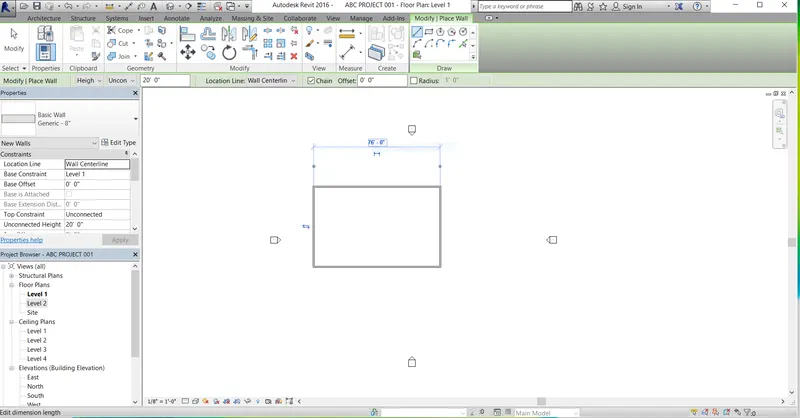
Now go to elevation view
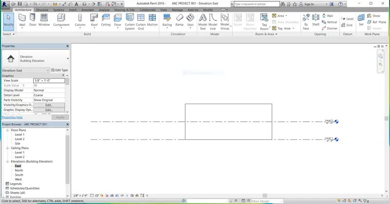
Now select level tool from top ribbon tab
Provide offset of 10'
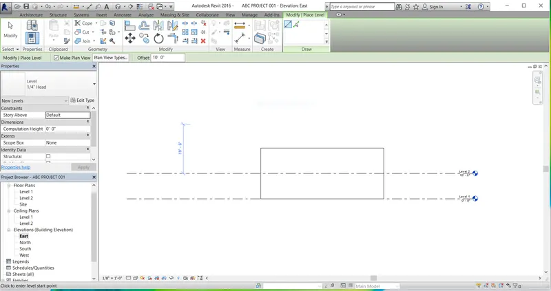
Click on Pick Lines tool
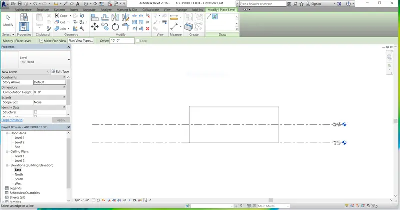
Now click on LEVEL 2
LEVEL 3 will be generated in elevation
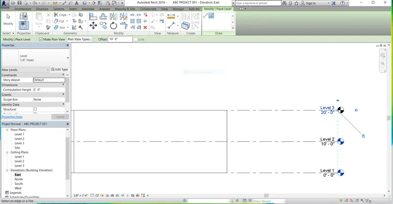
Now again select Level tool from ribbon tab
Provide offset 10'
Click on Pick Lines tool
Click on LEVEL 3
LEVEL 4 will be generated
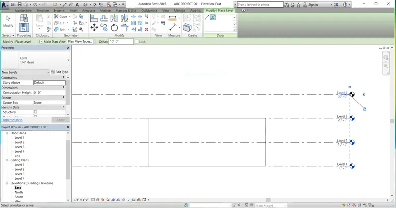
Now edit the levels names to Ground floor, First fllor, Second floor and Roof.
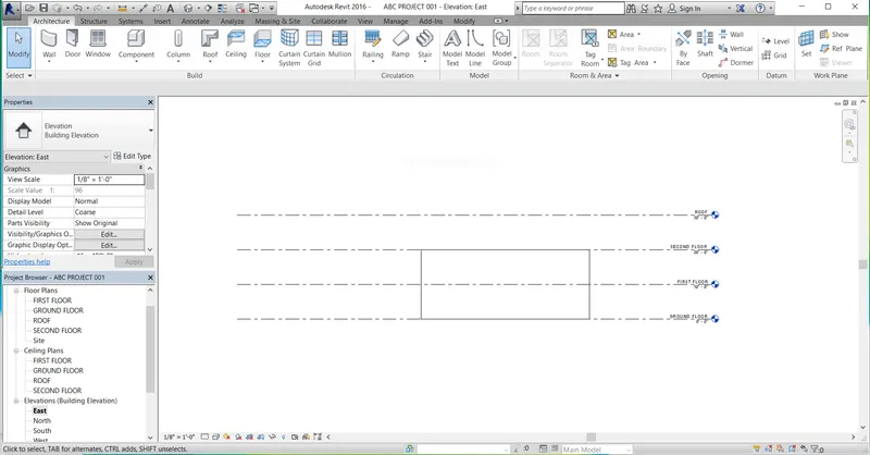
Finally levels had been created to our requirement.
AIM(2): To understand the concept of grids and to create the transverse grids A,B,C,D,E @ 10' spacing and longitudinal grids from 1 to 10 @ 20' spacing.
PROCEDURE TO CREATE THE TRANSVERSE GRIDS @ 10' SPACING AND LONGITUDINAL GRIDS FROM 1 TO 10 @ 20' SPACING:
Go to Architecture tab
Click on wall architecture
Draw the walls at 20' spacing longitudinally and 10' spacing horizontally
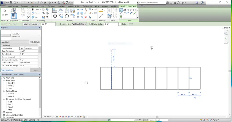
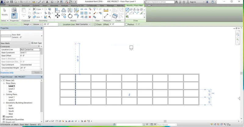
Now click on Grid tool
Select Pick lines tool
click on longitudinal walls either interior or exterior
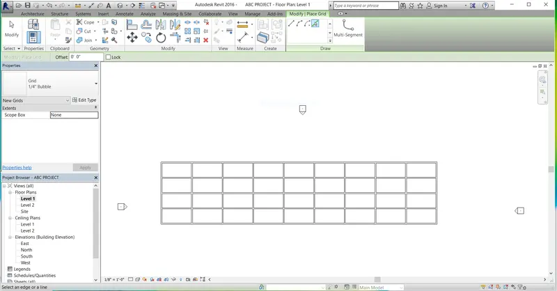
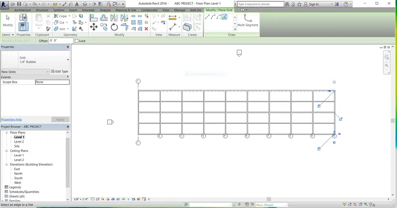
Drag the grids to a level
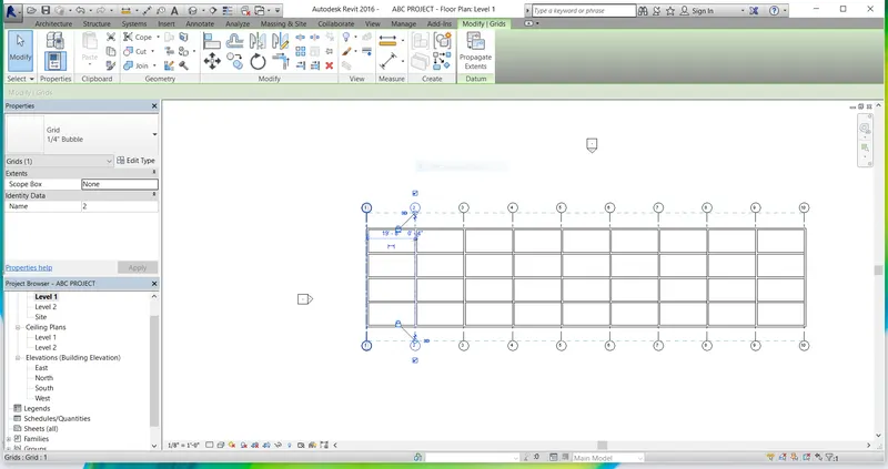
Now click on Grid tool
Select Pick Lines tool
Click on transverse walls either interior or exterior
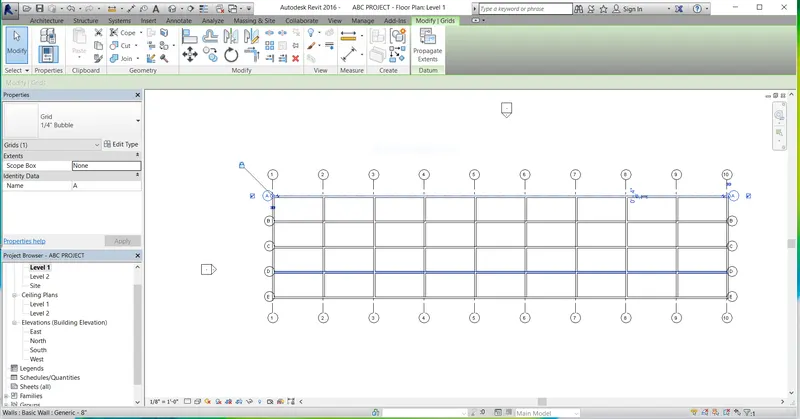
Drag the transverse grids from A to E to a level
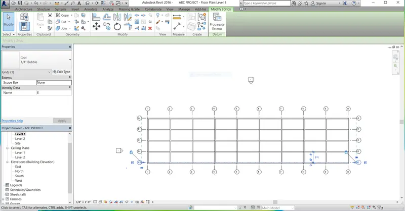
Finally Longitudinal and transverse grids had been created
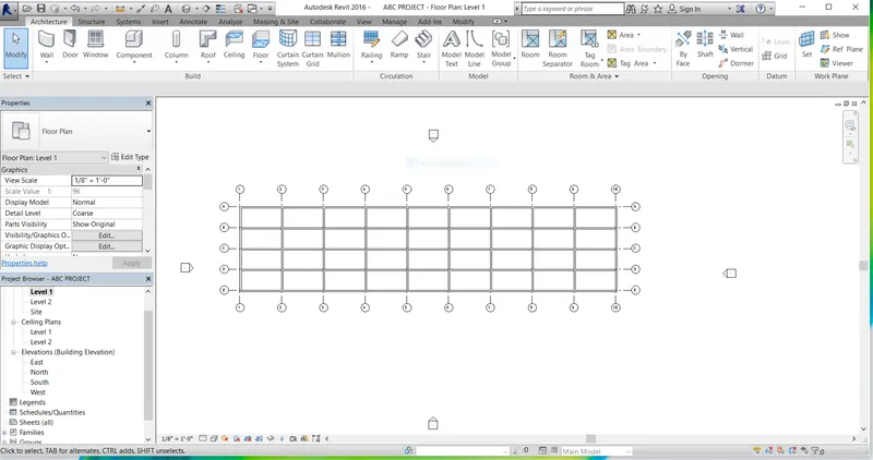
Grid lines are used for proper coordination in modelling a project.
5. AIM: To create a layout of residential unit of my own.
Procedure:
Go to architecture tool
select wall architecture
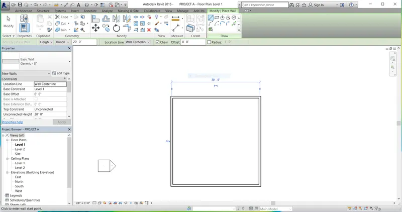
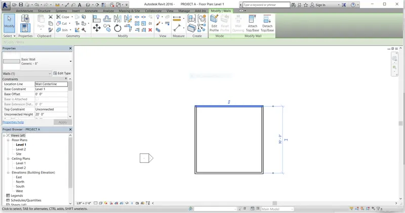
Draw the layout of the house 30' X 30'
6.AIM: To draw the rooms inside the layout of the house and provide dimensions for every room.
Procedure:
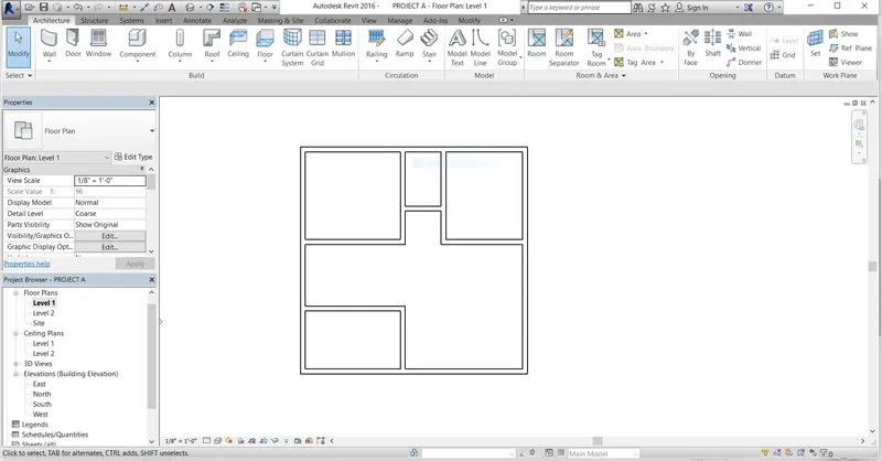
Draw the rooms in the layout 30'x30'
Now go to Annotate icon
Select Linear dimension tool
Click on the walls of every room to provide dimensions
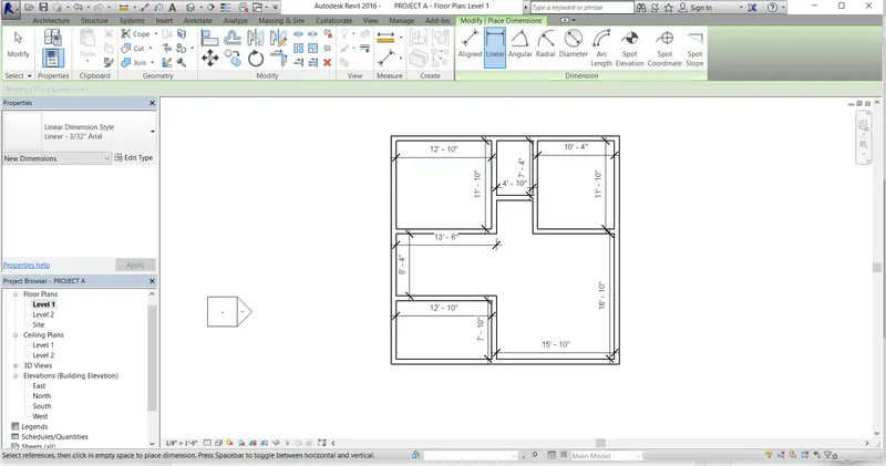
7.AIM: To identify the residential model elements such as Doors,Windows,Tables,Chairs,Couch,Bed,Laps from the library and insert these elements into the residential model.And also to save the project.
Procedure:
To place the doors in every room
Go to Architecture tab
Click on DOOR tool
Click on Load Family tool
Select doors category
Selcet Residential family
Select double door exterior element for entrance
Press OPEN button
Select size of the door
Press OK button
Place the exterior door in the entrance 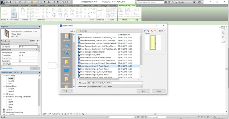
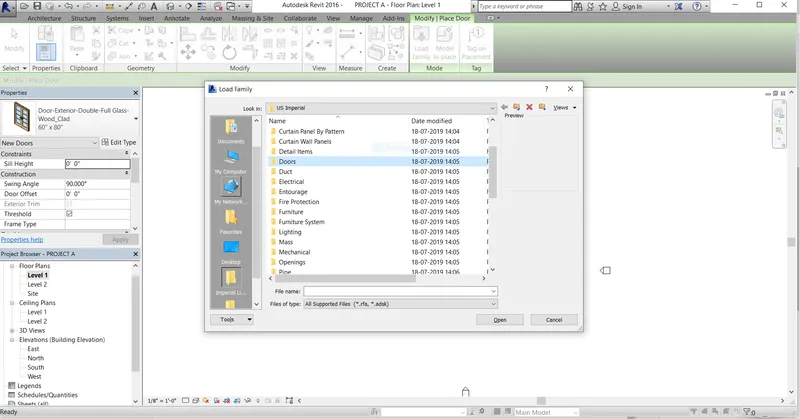
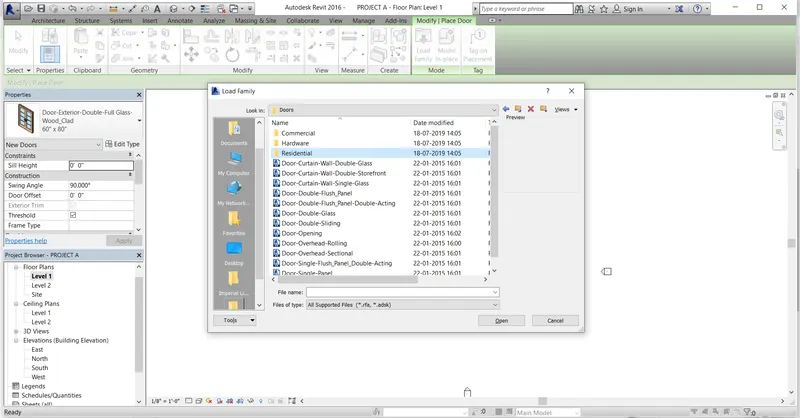
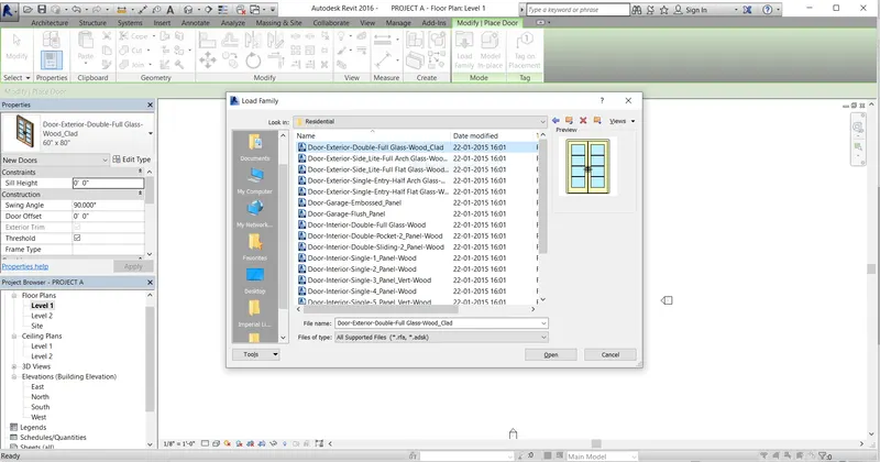
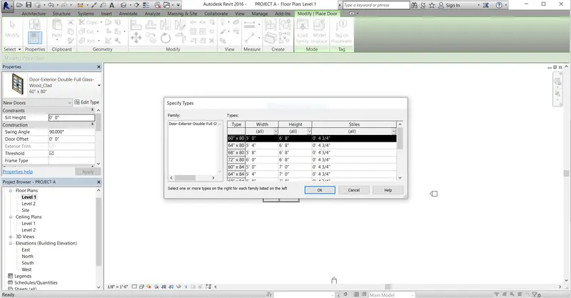
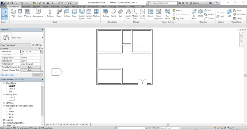
Now for interior doors
Go to door tool
Click on Load Family tool
select doors category
select residential family
select interior panel wood door element
select width and height of the door to required size
Press OK button
Place the interior doors in rooms
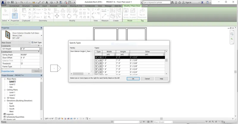
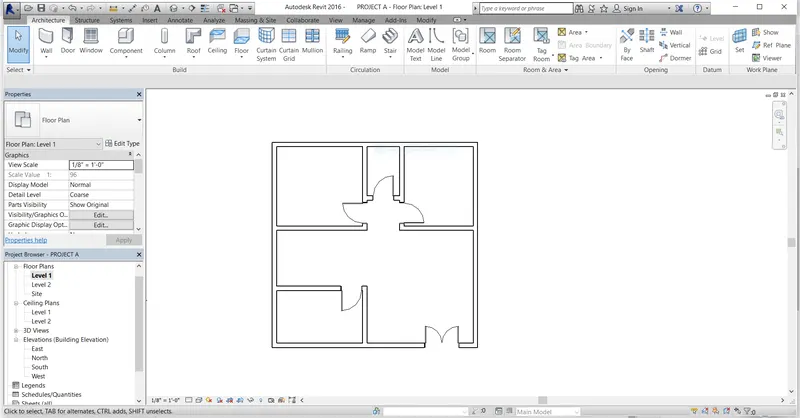
Doors had been placed in every room of the residential unit.
Procedure to insert windows in each room:
Go to Architecture tab
Click on Window tool
Click on Load Family tool
Select windows category
Select casement 3x3 window element
Press Open Button
Place the window in each room at required place
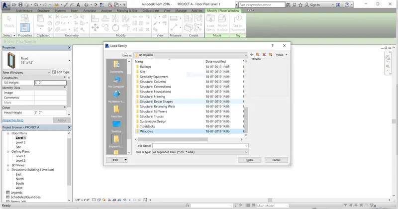
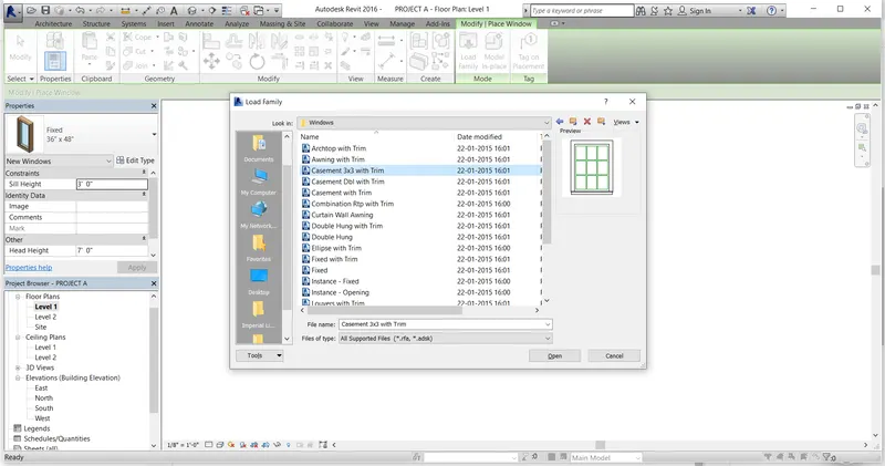
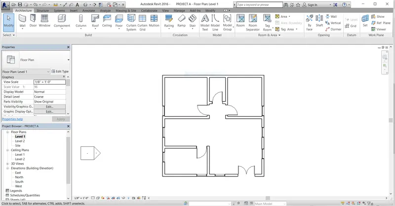
Finally Windows had been placed in every room of the residential unit.
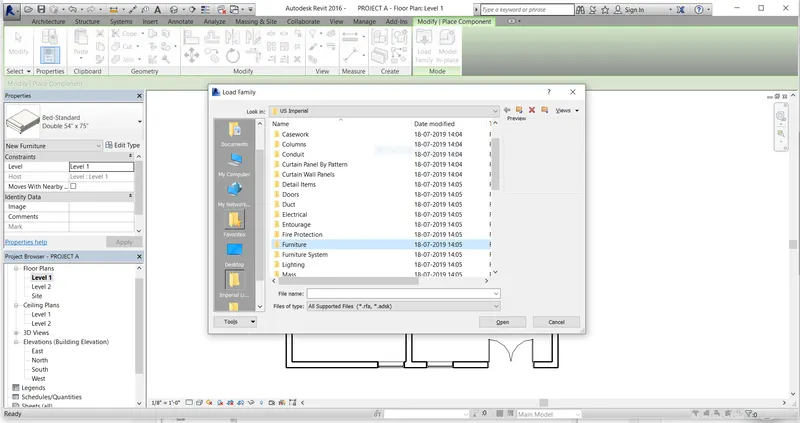
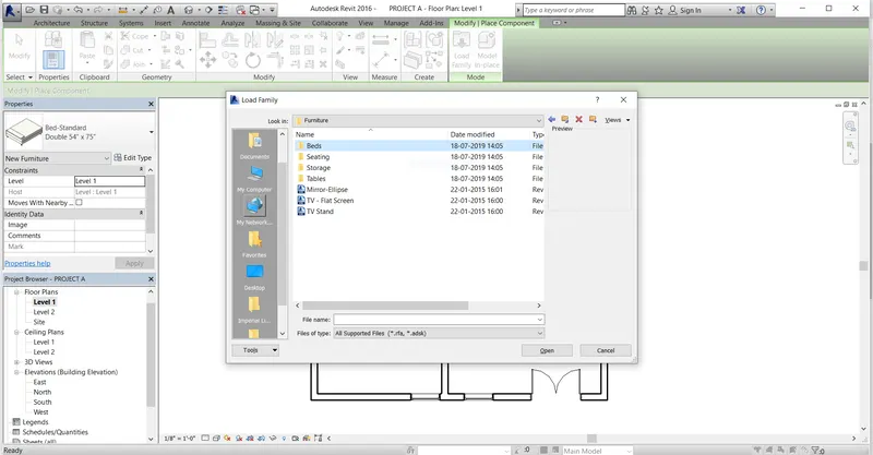
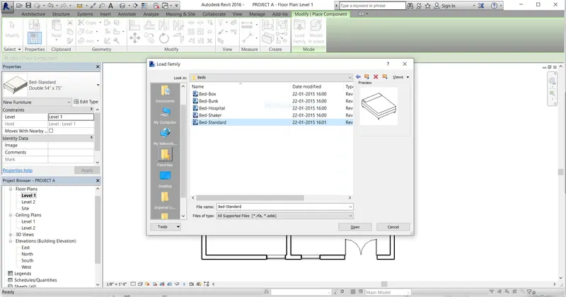
Procedure to insert the beds in the residential unit
Go to Architecture tab
Click on component tool
select place a component tool
click on load family
select furniture category
select beds family
select bed standard element
Press Open button
Place the beds in each bedroom
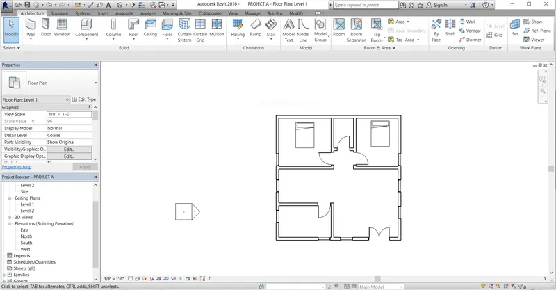
Finally Beds had been placed in each bedrooms of the residential unit.
Procedure to insert the tables in the residential unit
Go to architecture tab
click on component tool
select place a component tool
click on Load Family tool
select furniture category
select tables family
select table dining round with chairs element
Press Open button
Place the dining table in dining room
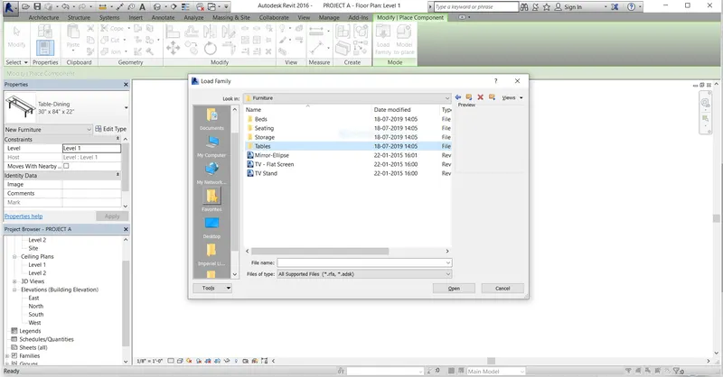
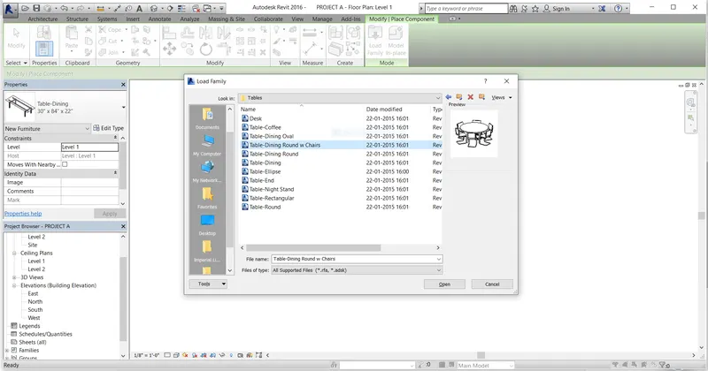
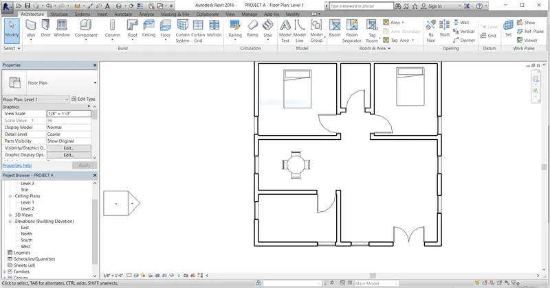
Finally Dining table had been placed in the residential unit.
Procedure to insert the chairs in the residential unit
Go to architecture tab
click on component tool
select place a component tool
click on Load Family tool
select furniture category
select seating family
select chair corbu element
Press Open button
Place the chair
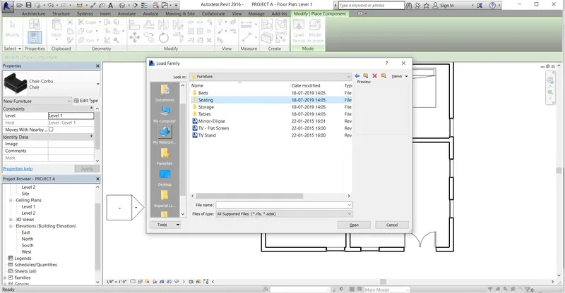
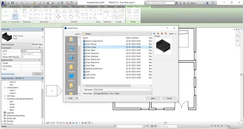
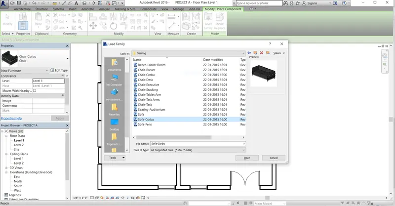
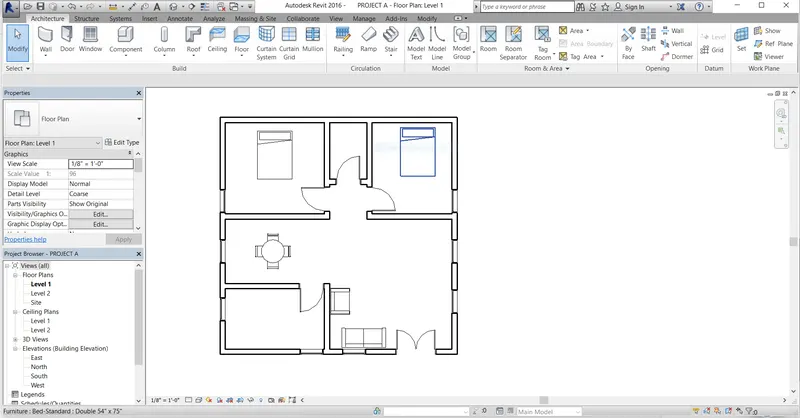
Finally seating chair and sofa elements had been placed in the residential unit.
Procedure to insert the lamp in the residential unit
Go to architecture tab
click on component tool
select place a component tool
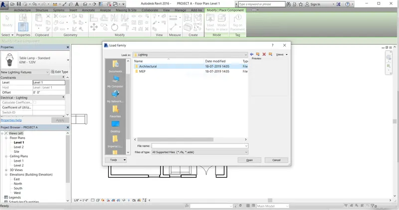
click on load family tool
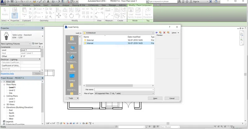
select lighting category
select architectural
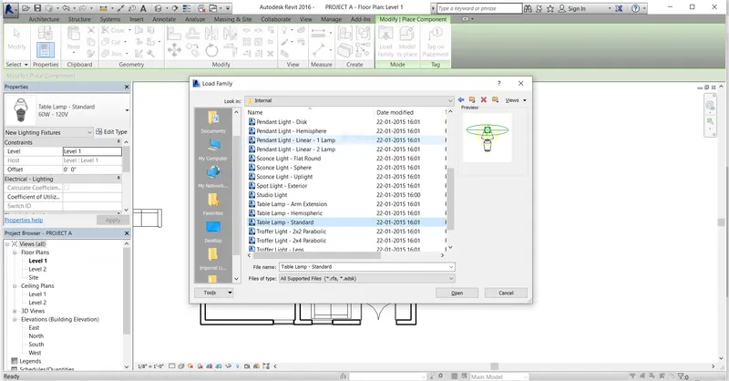
select internal
select table lamp standard element
Press Open button
Place the lamp
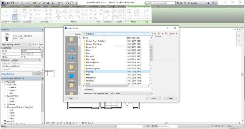
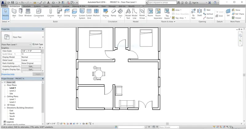
Finally the lamps had been placed in the residential unit.