Creating Levels, Grids, Layout and model elements for a residential unit using REVIT
1) What is BIM? Summarize the features of BIM and benefits of using BIM over 2D CAD tools
BIM is known as building information model which is used in architectural, engineering and construction fields. It is a concept created by autodesk and autodesk revit is one of the software tools which achieve BIM.
BIM is divided into two concepts
- Coordination - It helps to maintains coordination between multiple disciplines such as engineers, architects and construction managers.
- Computation - It helps in computation such as material schedule, quantity schedule, energy evaluation, robo structutal analysis ie reponse to loads applied on buildings.
BIM also helps in solving issues in pre construction process before leading to delay and become costly. It brings all the information together and enables sharing the information. Retrieval of information is also possible which increases productivitya and increase speed of project delivery.
In 2D CAD tools it is difficult to visualize dimensions and realistic views. In 3D CAD tools a project is visualized in realistic digital environment but it is not a real time tool. 3D/2D tools consists lines, surface features, solid features which is purely graphical representation of building components and if any changes are needed, it is necessary to make revised version of each plan which increases time consumption in a project. BIM is more than a 3D model, the objects in BIM store data and reflect the updates of the model, if any change occurs. Therefore BIM acts as a real time tool which minimises time consumption in a project. This allows to maintain consistent and coordination between architects, structural engineers, MEP engineers and construction managers. Further more with BIM concept accurate virtual model of a building.
2) i) Understand the concept of Categories, Families, Elements, Instances in Revit.
Family and categories helps to add details in project space. Revit offers huge database of component that lets add details to project. These components are the categories and families. Categories are properties in revit that are already present and the properties are predefined by the software. Example doors, windows, floor or wall they come under a category. Example if a wall is created and it is saved under a category, these category are predefined by revit. New category can be created and also elements are defined in it. Family is a group of elements that share a common property. Example door is a category and one kind of door such as single flush door with different sizes makes different elements comes under a family. Therefore door is a category, single door flush is a family and different sizes of door comes under different elements. Instances is giving different value to each element.
ii) Go to Insert Tab, choose a category. Pick a family and element. Understand the instances and insert it to Revit model
AIM : To insert an element of a family choosen from a category
Procedure :
- Go to insert tab and click on load autodesk family
- Select window (category)
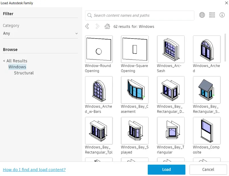
- Now select Windows_Arched
- Click on load
- Select wall in architectural tab
- Draw a wall (Basic wall)
- Select window in architectural
- Select Windows_Arched 1360 x 910mm from properties and draw on the wall
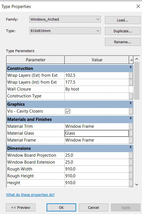
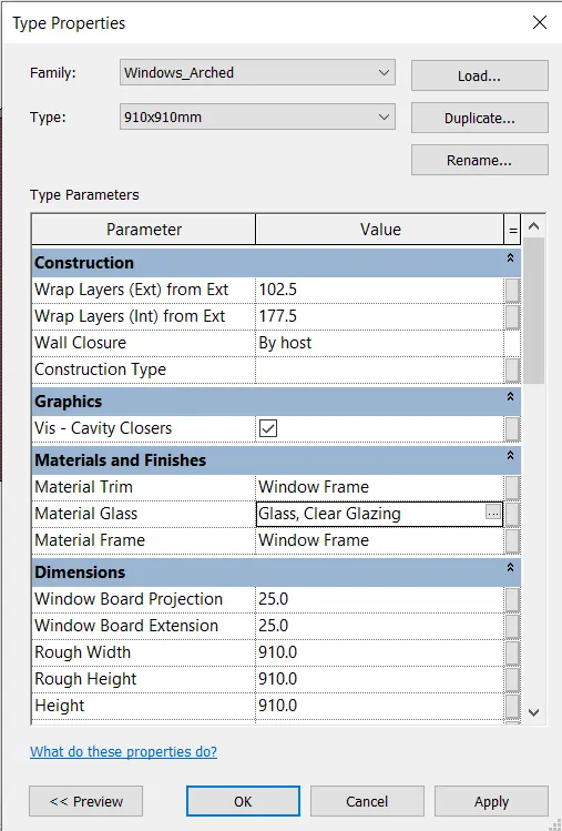
- Go properties of Windows_arched and go to edit type and changing properties of materials or dimensions, assigning a particular value makes instance.
RESULT :
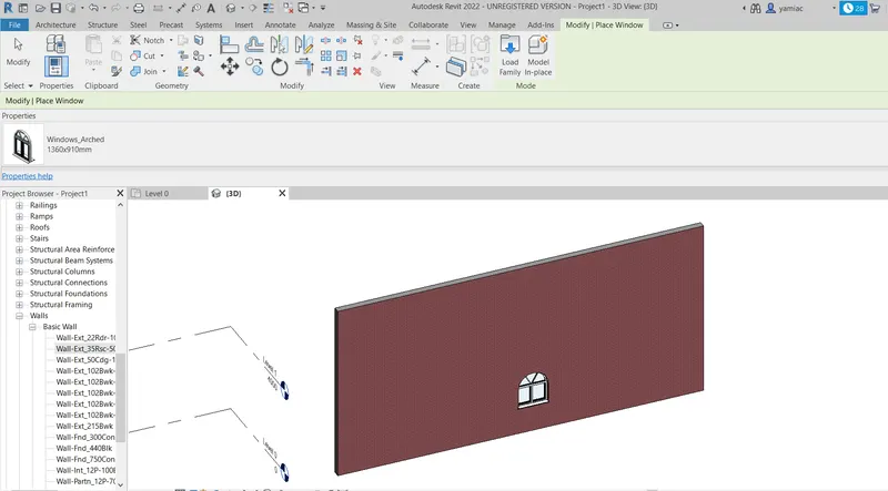
- Material property of window changed from glass to glass, clear glazing
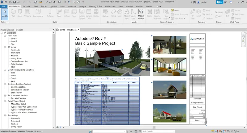
3) Setting up a Project – Open a project file with architectural template. Save the file with appropriate name. Set up the project units to Imperial / Metric based on your convenience of modelling. Complete the project information under Manage tab. Set up the maximum backups for project file to 3
AIM : To set up a project file using architectural template
PROCEDURE :
- Open revit software
- Select architectural project template
- Enter the name of the file as "Project2"
- Click on options and enter "3" in maximum
- Press ok
- Select architecture or structure tab
- Now type "UN"
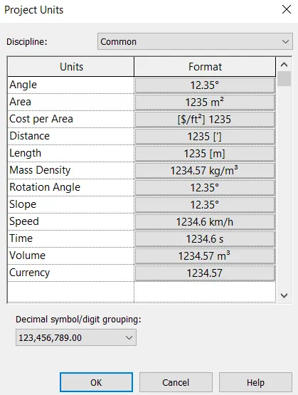
- Select length and then select meters, Press ok
- Now go to manage tab
- Click on project information
- Enter project details as given below
- Organization name: REVIT
- Organisation description : SOFTWARE
- Building name : MNS
- Author : YS
- Project Issue date : 03/09/2021
- Project Status : NEW BUILDING
- Client Name : AB
- Project Address : XYZ, AS COLONY, HYDERABAD
- Project Name : SCHOOL BUILDING
- Project Number : 003
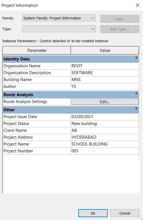
RESULT :
Architectural template file created with project information
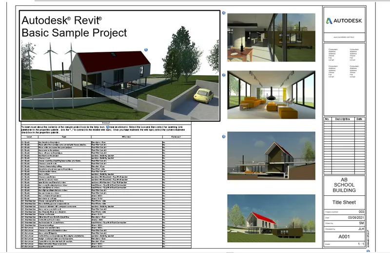
4) i) Understand the concept of Levels and Grids. Follow the naming and conventions.
Level is used to define vertical height of a model in revit software. In architecture model, level acts as a datum and in structural model, level acts as a datum as well as it gives analytical details. Levels can be edited by changing the elevations. The levels in top constraint is assigned to model elements, so that model elements such as wall automatically adjust itself to assigned levels.
Grids are straight lines or arcs or multisegmented are made to locate model elements example to place columns grids are necessary. Grids are used in both structural and architectural disciplines. Grids can be placed either right to left or left to right and it needs to be incremental order. Grids are placed based on model element that is on boundary. Grids lines are placed vertically or horizontally and while naming grids particular sequence is followed. Vertical grids lines are labelled from right to left in numerical order. Horizontal grid lines are labelled from top to bottom in alphabetical order.
ii) AIM : To create the given levels using REVIT software
PROCEDURE :
- Open revit software
- Select new
- Select architectural template and press okay
- Save the file
- Go to manage tab and click on project units
- Click on length and change the units to feet
- Click on elevation in project browser
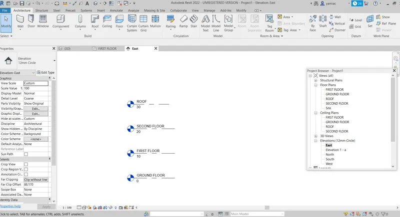
- Now rename level 0 to ground floor
- Rename level 1 to first floor and enter distance as 10'
- Go to architecture tab and click on level in datum panel
- From floor floor draw a level at a distance 10' and rename the level as second floor
- From second floor draw a level at a distance 10' and rename the level as roof
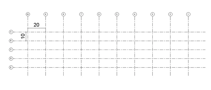
- Now go to level ground floor, create horizontal and vertical grids
- To create grids go to architecture tab, click on grid present in datum panel
- Create horizontal grid line (transverse) each at a distance 10' and name it as A,B,C,D,E
- Create vertical grid lines (longitudinal) each at a distance of 20' and name it from 1 to 10
- Using linear tool in annotate tab mark the dimension
RESULT :
Different levels are created
Transverse and longitudinal grids are created
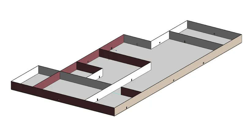
5) AIM : To create 3D residential unit using REVIT software
PROCEDURE :
- Open revit software
- Open revit software
- Select new
- Select architectural template and press okay
- Save the file
- Go to manage tab and click on project units
- Click on length and change the units to feet
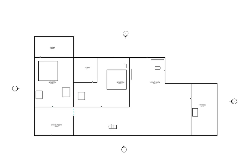
- Draw a layout as shown below
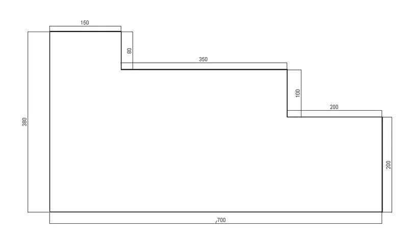
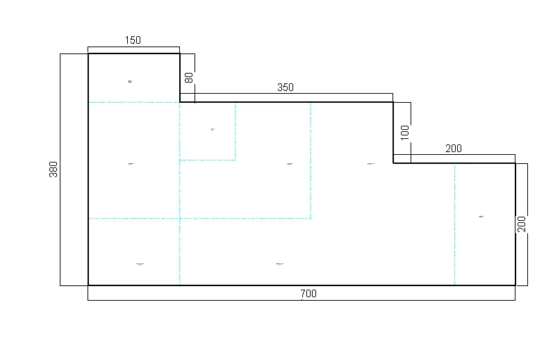
- Select "room separator" from architecture tab and divide the layout as shown below
- Select "room" in architecture tab and select according to layout
- Select "tag room" in architecture tab and select rooms
- Enter the name of the rooms
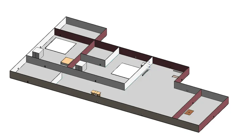
- Create walls on the room separated
- Select door in architectural tab and place the doors as shown below
Type 1 door : 1510 x 2110mm
Type 2 door : 810 x 2110mm 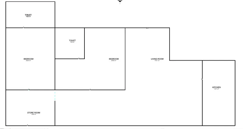
- Select window from architectural tab and add to the layout as shown below
- Type 1 window 910 x 910 mm
- Type 2 window 1360x 1210 mm
- Now select floor in architectural tab
- Select exterior walls and click ok in the mode
RESULT :
3D RESIDENTIAL BUILDING IS CREATED
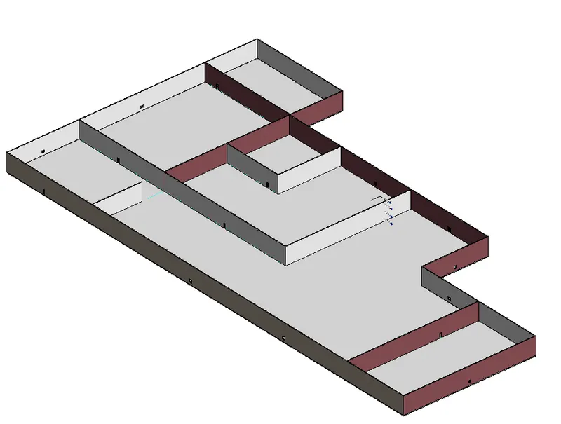
6) In the layout created draft the level of details you are planning to include – Dimensions of room, components you plan to add in the residential unit.
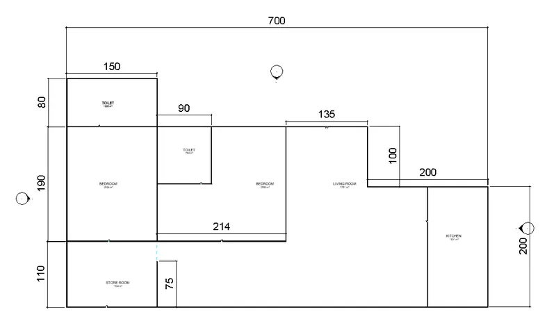
AIM : To add details, dimensions and components in the layout created
Procedure :
- Open layout plan of residential building created
- Select linear tool in annotate tab and mark the dimenions on the layout
- Doors are added
- Type 1 door : 1510 x 2110mm
Type 2 door : 810 x 2110mm
- Type 1 door : 1510 x 2110mm
- Windows are added
- Type 1 window 910 x 910 mm
- Type 2 window 1360x 1210 mm
RESULTS :
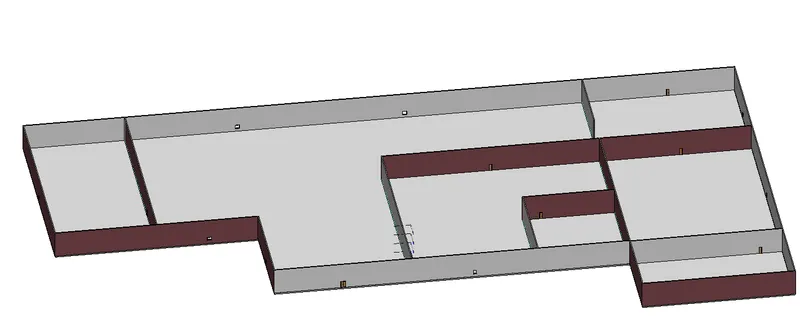
3D residential building with doors and windows
7) Identify the residential model elements such as Door, Windows, Tables, Chair, Couch, Bed, Lamps from the library and insert them to the model .
AIM : To insert elements such as doors, windows, tables, chairs, couch, bed, lamps from library in the model
Procedure :
- Copy the previous project and rename it as assignment 3
- Open the newly created project
- Doors and windows are already added
- Now add Tables, chairs, Couch, bed, lamps
- Go to insert tab
- Click on Load autodesk family
- Go to furniture
- Load following items
- Bed
- Cabinet storage
- Cabinet file flat
- Chair
- Sofa
- Desk
- TV
- Coffee Table
- Study table
- Go to project browser and drag all these items from furniture category
- Place it in the layout
RESULT :
Elements inserted in the residential building