Creating Levels, Grids, Layout and model elements for a residential unit using REVIT
1)BUILDING INFORMATION MODELING:-
BIM is a process in which all the information of the 3D building models are linked and incorporated to produse a comprenhive 3D model .Therefore revit is one of the software which supports BIM by creating the data based model of architectural design ,structural design.
BIM is an intelligent model-based process which creaats 3D building design models containg every inforamtion needed for the construction of a building .it facilitates the co-ordination and collaboration between different team associated with the project.
THE BENIFITS OF USING BIM OVER 2D CAD TOOLS:-
- BIM offers a more complete representation of a building’s design. It takes more than the building’s core components into account. For example, BIM allows you to design electrical and HVAC systems, as well as the building itself. This means the project team can take full advantage of the space and resources available.
- BIM pulls your documents into a single database. Several people can work on the same model and save it to the cloud. This allows for instant updates, so you won’t waste time searching for documents when you need to make changes.
- A BIM model will allow you to prefabricate important components ahead of time. You won’t have to adjust them based on the building design. Instead, such components are part of the initial design.
- You can provide much more to your clients using BIM than you could with CAD. The models you give to your clients update constantly as you work on your project. Your client can check in any time, which leads to quicker approval for milestones and more efficient project development.
- Resource tracking is a key component of BIM models. You’ll be able to figure out how much of each resource you need during the design stage. This improves the flow and efficiency of construction.
2Q)
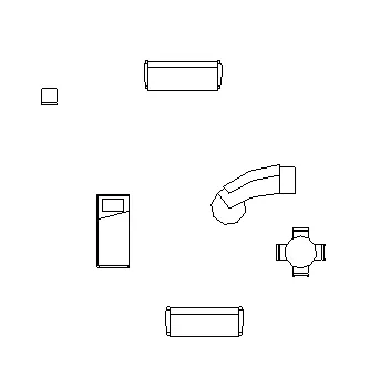
AIM:To insert different catogories,familes ,elements by using REVIT.
PROCEDURE:
- First open the revit then click on new project and save the project by giving some name to it.
- Next go to architect tool bar in that select click on components and then next click on load components in that select diffirent catogories,families and elements.
The above are some families which are taken from the insert toolbar in that select load components and select required componenets and insert.
3Q)
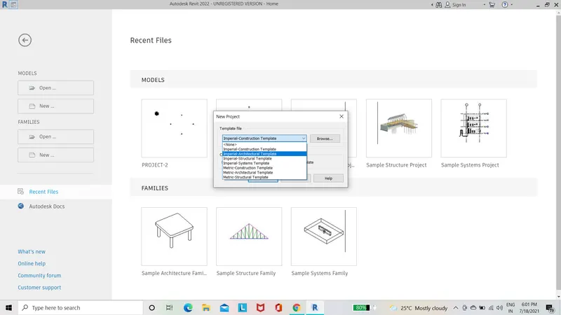
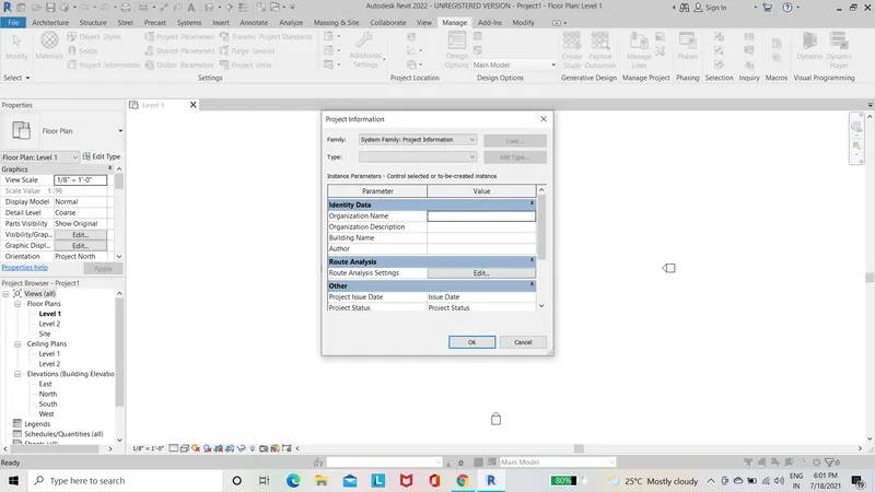
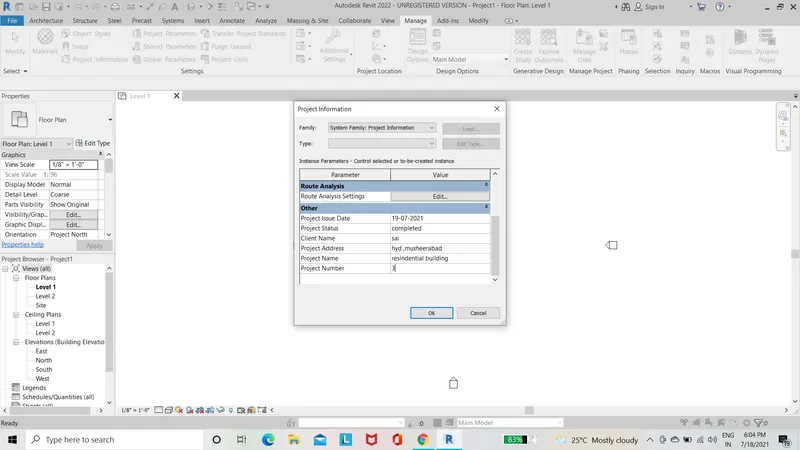
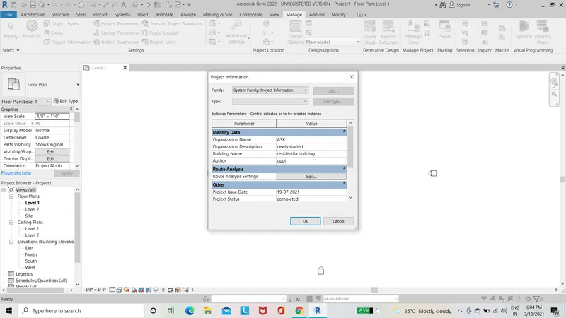
The setting up a project in architectural template and saved it by using some name and in project information given all the information about project like name,number,address and issue date of the project the images are givel below.
4Q)
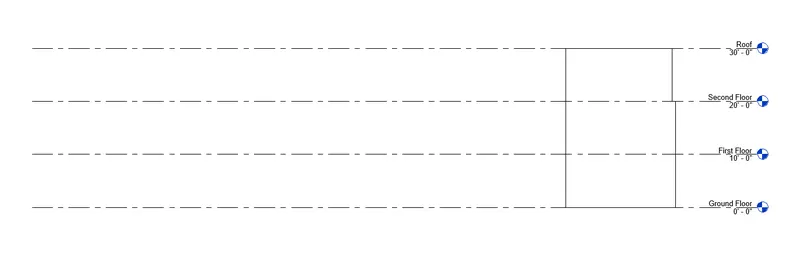
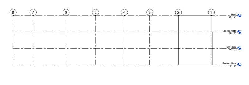
AIM:To creat levels by using the REVIT software.
PROCEDURE:
- First open the revit then click on new project and save the project by giving some name to it.
- Next draw the layout of a building on the drawing sheet by using architect toolbar in that select floor and draw the floor in the sheet.
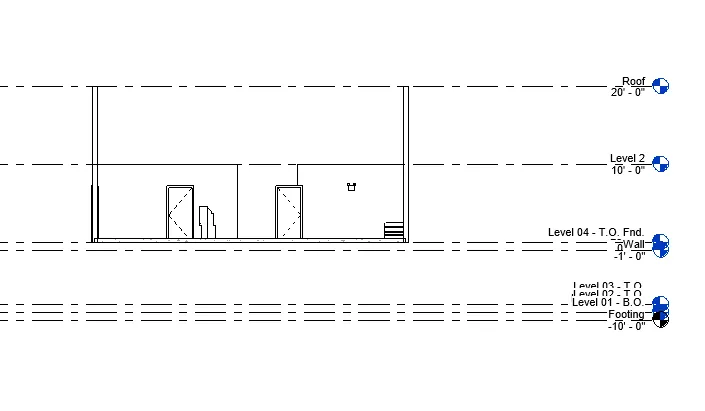
- Then go to elevation in that create different levels by using architect tool bar in that click level.
- After creat the levels we can change the name of the level by select the level and edit it.
- The grids are also drawn by using the architect tool bar in that selcet grids and draw the grids.
5Q)
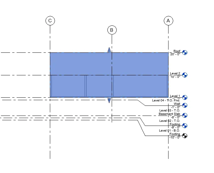
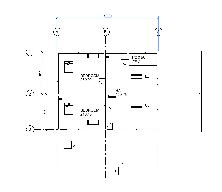
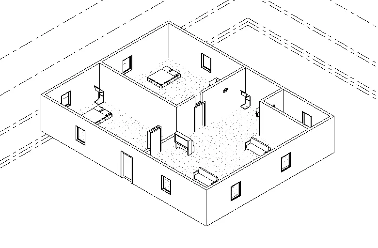
AIM:To draw the 3D modelling of residential building by using the REVIT software.
PROCEDURE:
- First open the revit then click on new project and save the project by giving some name to it.
- Next draw the layout of a building on the drawing sheet by using architect toolbar in that select floor and draw the floor in the sheet.
- After draw the layout of a building then go to level one in that select wall tool in the architect toolbar draw the wall by floor by giving height and width to the wall.
- Then give doors and windows to the wall by using door and window tools in the architect toolbar.
- Give dimensions to the layout by using the annotate toolbar in that select linear or aligned which is required for the drawing.
- The text in the above drawing is written by using the text tool in the annotate toolbar.
- Draw the grids to the walls by using grids tool in the architect toolbar.
- Next go to view toolbar in that selcet 3d view and layout is converted to 3d modelling and save it by giving some name to it.
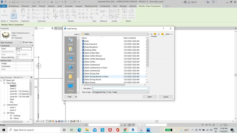
- After that go to level 1 and insert different catogories,families and elaments which are suitable for the resiential building by using the architect toolbar in that select component in that select load components from this insert different families.
THE TOOLS USED TO DRAW THE ABOVE DRAWINGS ARE:
- Architect tool
- Annotate tool
- View tool
- Insert tool
- Manage tool
- grid tool
- level tool
- wall tool
- window tool
- components tool
- floor tool