Creating Levels, Grids, Layout and model elements for a residential unit using REVIT
BIM , CATEGORY,FAMILY,ELEMENT,SETTING UP OF PROJECT,LEVELS AND GRIDS, 3D MODELLING AND ADDING COMPONENTS IN A RESIDENTIAL BUILDING
1. BIM and its benifits over 2d cad tool
- BIM is Building Information Modelling.
- It is a concept created by Autodesk .
- Rivet helps in achieving BIM as a process.
Features in BIM:
- BIM is divided into 2 concepts:
a. Coordination :- Coordination is the key feature in BIM.
-Rivet helps in coordination of multiple disciplines.
- eg: Rivet offers in coordintion of projects in architecture, structural, mechanical etc. in single project as independent design theme units.
b. Computation:- Calculation of quantities of material , performing analysis
- To create material shedules, quantity shedule, perfoming energy analysis in Rivet
- In structural discipline in Rivet, robostructural analysis that helps in computing the response to the load applied in a building.
- Autodesk CFD,for computing floor and thermal computation in specification to mechanical engineering.
- Rivet is a BIM tool that helps in achieving coordinating and computation as apart of model.
Benifits over 2D Cad tool :
Saving time:
-The modification of the model in one view will inturn reflect on all other view.
- Unlike 2d Cad tool , we do not have to edit the modification in the plan, elevation etc. , here in Rivet changes made in one view will be automatically loaded in all other views.
- If we select a wall in one view, the same wall in all other views will be selected and gets modified thus saving time.
- The changes will affect the quantities, computation also.
- It will also reflect in the paper space and model space.
2. Category , family and element
Category:
- Categories are group of elements having common properties.
- It is predefined by the software.
- Eg: A wall or door, windows is an example of category.
- We can insert element of our choice and create a category.
- It controls the organization , visibility, graphical representation and sheduling options of the family within the project.
Family:
- Family is different elements having same properties
- Eg: Single flush door - It has different sizes having the same property
- Family is a grouping of 2d or 3d information that serves to represent a discrete building or documentation element in the project.
- It defines parametric, graphical and documentation requirements.
Element :
- Element is the basic feauture which cannot be subdivided
- Eg: In single flush door , the different sizes represent the element.
- single fiush door of size 30"x80" , 30" x84" ,32"x84".
- Element is a specific representation in a family defined by distinct parametric, graphical and documentation characteristics which make it unique from other types in the family.
Instance:
- It is an individual representation of a type in the project defined by unique parametric ,graphical and documentation characteristics which make it unique from other instances in the project.
Eg:
- Go to insert tab, click on load family
-
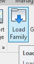
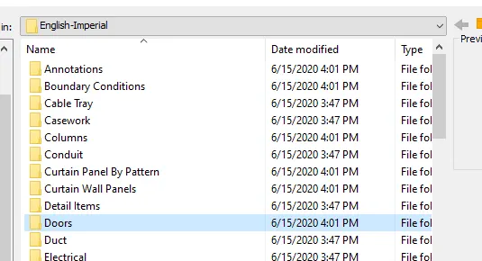
- A Dialogue box appears, from that click on doors, which is the category
-
- Another list of doors appears, double flush panel, double glass, double sliding these are families.
-
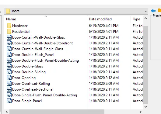
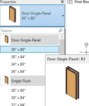
- Click on door single panel
- Then a dialogue box showing different sizes of doors appears , the different sizes represent elements.
- 30" x80" , 30"x84" ,32"x84" ,34"x80".
-
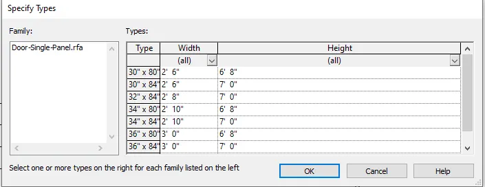
- Select 30" x80" (element)and click ok , then the door gets loaded in the door properties in architectural tab.
- Go to architectural tab, select doors (category) , go to single flush ( family) , and select 30"x80" ( element ) which is loaded .
-
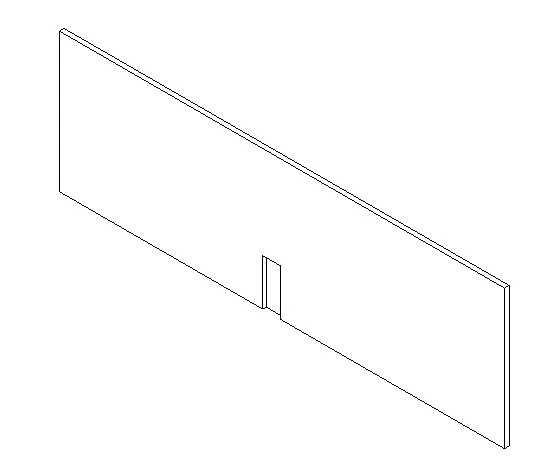
- Click on the 30" x80" size door and place it in a wall craeted , this is the instance.
-

3. Setting up a project
Aim : Setting up rivet softwate for a project:
- Creating template and setting units
- Saving the file
- Adding project information
- Creating backups
Procedure:
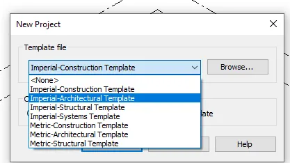
- Step 1: Open the project file , select architectural imperial template imperial for units .
-
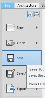
- Step 2:To save the file : Go to file tab and click on save option and save the name as "Project 2".
-
-

- Click on save.
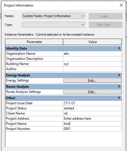
- Step 3:Go to manage tab ,click on project information tab
-
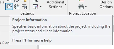
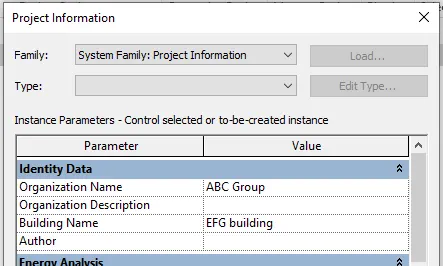
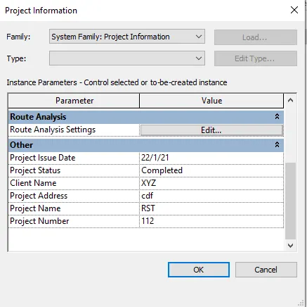
- The project information dialogue box appears ,enter the organisation name, project details etc
-
-
Step 4: Setting backups:
- Go to file menu , click on save as ,click on project .
-
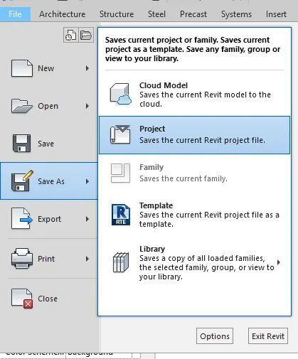
- Click on options in the save as dialogue box
- File save option dialogue box appears , enter the no: of backups as 3
-
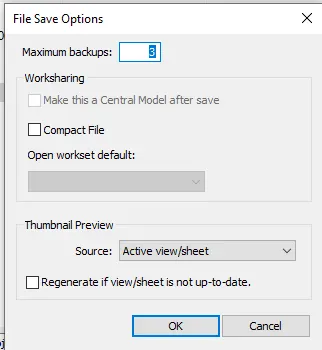
- Click on OK and then click save.
Result: Rivet software is set for the project:
- Creating template
- Saving the file
- Adding project information
- Creating backups
4. Levels and Grids
Aim : To create levels and grids.
Levels:
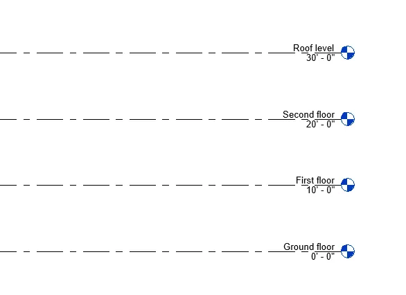
- Ground Floor @ 0’
- First Floor @ 10’
- Second Floor @ 20’
- Roof @ 30’
Grids:
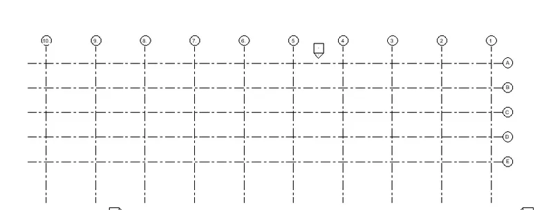
- Transverse Grids A, B,C,D, E @ 10’ spacing
- Longitudinal Grids from 1 to 10 @ 20’ spacing
Tools:
Level
Grid
Procedure:
Creating levels:
- Step 1: Open a new project with imperial architectural template.
- Step 2: Go to elevation - East in project browser
- Step3: Already there are two levels by defualt.
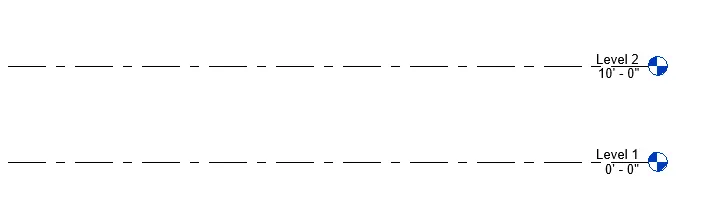
- Step 4:Level 1 at 0' and level 2 at 10'
- Step 5:Rename the level 1 as ground floor by double clicking the level .
- Step 6: Rename the level 2 as first floor -10'.
-
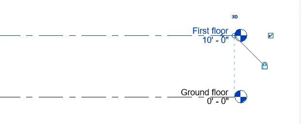
- Step 7: To create new level, in architecture tab click on levels,clcik on pick line option and give the offset as 10' and then click on the first floor level.
-
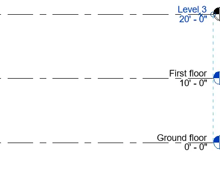
- Step 8: Level 3 is craeted at 20' from the ground floor
- Step 9: Rename the level as second floor by double clicking the text of level.
-
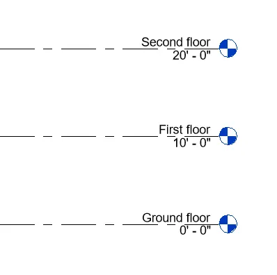
- Step 10: Similarly create the roof floor by offseting 10' from the second floor level.
-
Grids: Longitudinal gridsare drawn from right to left 1 to 10 and transverse grids from top to bottom A to E.
- Step 1: Go to plan view, in the architecture tab, click on grid.
- Step 2: Click on line and draw the grid line on the right side of the workspace.
- Step 3: The grid number will be represented as 1 , if not double click and enter the value 1.
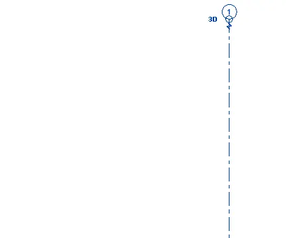
- Step 4: Again in architecture tab , clickon grid and now select pick line and give the offset as 20' and click on grid 1.
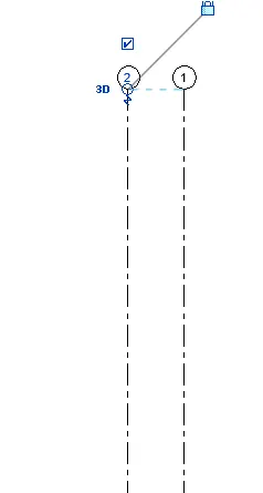 , grid 2 is created.
- Step 5: As the distance between the grid is 20' without moving out of command , click on grid 2 , thus grid 3 willbe created.
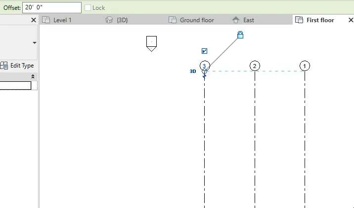
- Step 6: Simlarly create 10 grid line with a spacing of 20'.
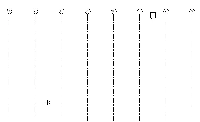
- Step 7: In transverse direction , draw a grid by line tool and mark as A in top.
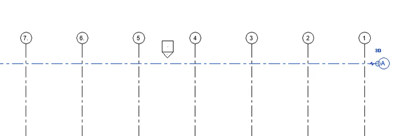
- Step 8 : By pick line give an offset of 10' and pick the first grid
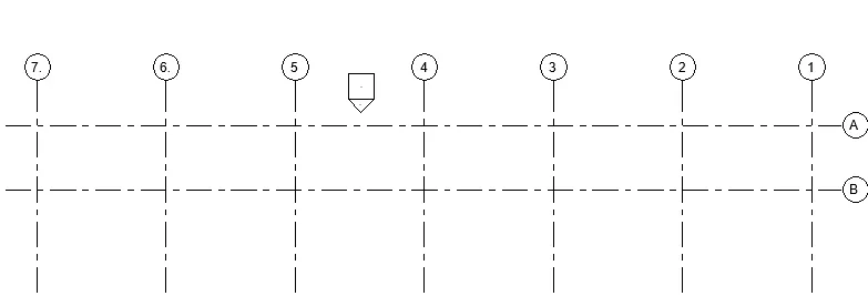
- Step 9: As the distance between the grid is 10' , click on the B grid , then C will be craeted at distance of 10' without exiting from the command.
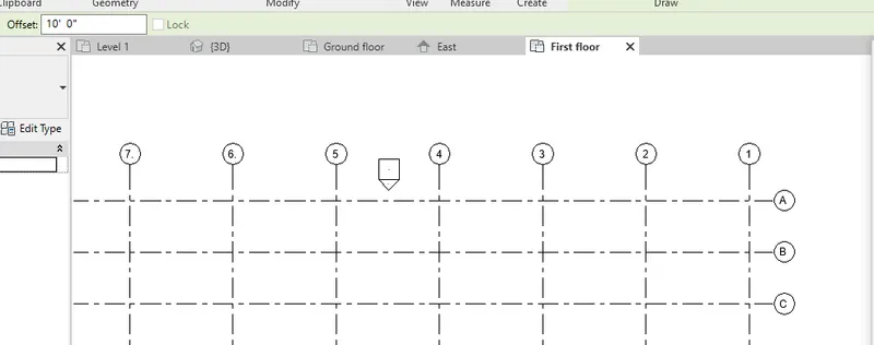
- Step 10 : Similarly create upto E grid.
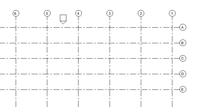
Result: Levels and grids are created.
5. 3d modelling of residential unit.
Aim : To draw the layout of 3d modeeling of resiendtial unit.
Tools used:
Wall - In architectural tab.
Project information- In manage tab
Procedure:
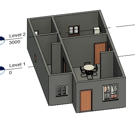
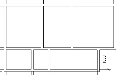
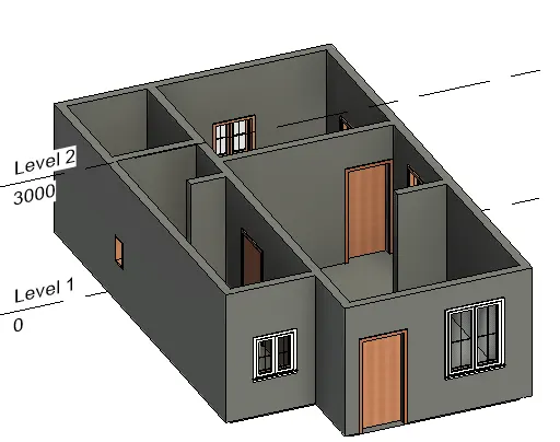
- Step 1: Go to metric architectural template , then create a new workspace.
- Step2: In manage tab go to project information , and add the informations
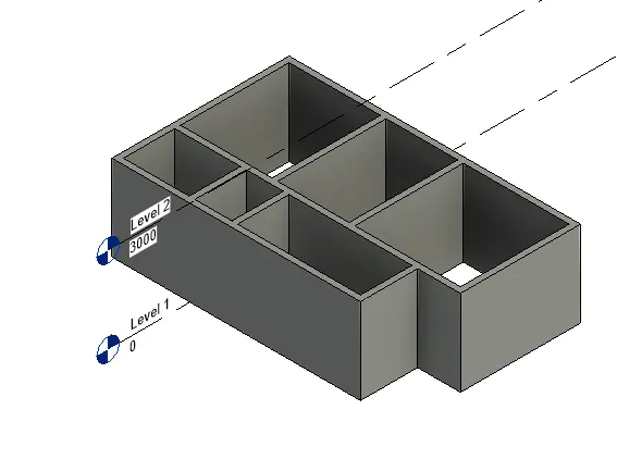
- Step 3: Click on wall in architectural tab, in plan view draw the wall.
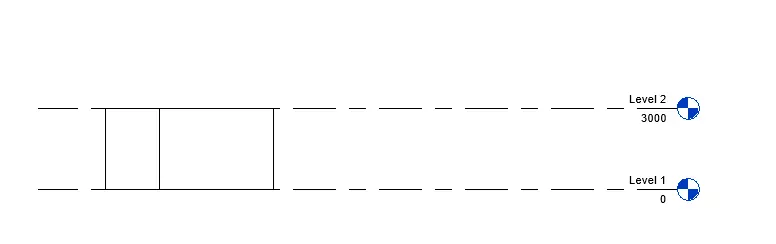
- Step 4: Select height and draw the wall in level 1 .
- Step 5:Change the level 2 to 3000mm if it is not.
- Step 6: Draw the wall 200mm wall ,by clicking in the workspace .
Result: The layout of 3d residential unit is created.
6. Adding details of room and components :
Aim : Adding details of room and components
Tools used:
Door- In architectural tab
Room- In architectural tab , to add rooms
Window- In architectural tab
Floor- In architectural tab
Procedure:
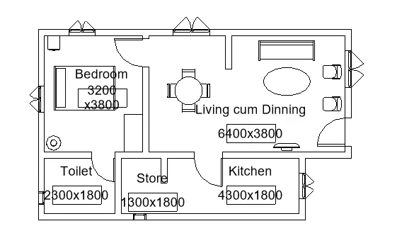
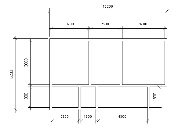
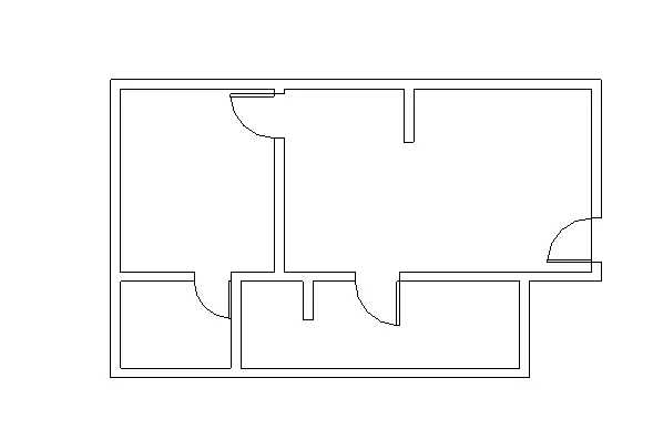
- Step 1: In the layout created ,dimnesion the rooms with annotate tab.
- Step2: Click on aligned in the annotate tab and click on the walls where the dimension is to be placed.
Placing of doors:
- Step 3: Click on door component from the architectural tab and place it wherever required.
- Step 4: Select single flush door of 915x2134mm for room doors and 762 x2032mm fro toilet door.
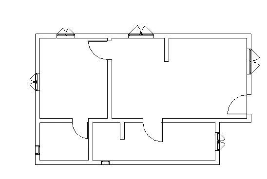
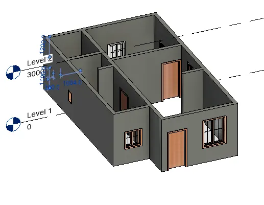
Placing of windows:
- Step 5: Click on windows from the architectural tab.
- Step 6: Place double casement window in the living room and dinning room 1200x1500mm.
- Step 7: Place 850x900mm window for all other rooms.
- Step 8: Place 406x610mm for toilet and store.
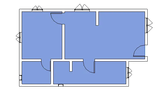
Creating floors:
- Step 9: Click on floor in architectural tab, select 150mm wall.
- Step 10: Select pick points and select the inside of walls and to draw click on draw line tool.
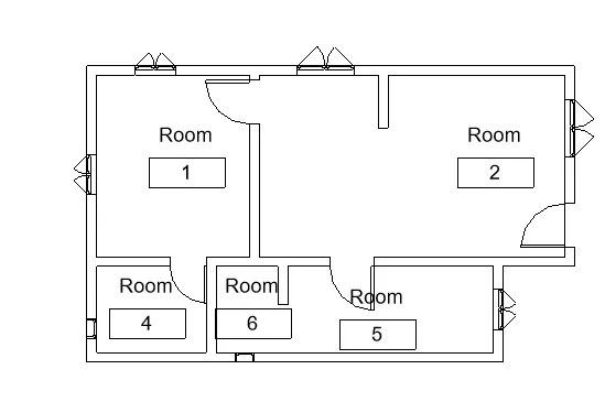
Rooms marking:
- Step 11: In architectural tab, click on rooms and place it in each room
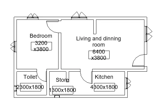
- Step 12: Double click the text and insert the room name and size.
7. Inserting model elements:
Aim : Inserting elements to the layout
Tools used:
Doors
Windows
Load family- from insert tab
Table
Chair
Sofa
Lamp
Bed
Storage
Procedure:
Doors:
- Step 1: From the architecture tab ,insert the doors.
- Step 2: Select single flush door of 915x2134mm for room doors and 762 x2032 mm for toilet door.
Inserting windows:
- Step 3: Click on windows from the architectural tab.
- Step 4: Place double casement window in the living room and dinning room 1200x1500mm.
- Step 5: Place 850x900mm window for all other rooms.
- Step 6: Place 406x610mm for toilet and store.
Inserting components:
- Step 7: From the architectural tab, click on components
- Step 8: Click on place a component, if not available go to insert and click on load families select the table , then click open.
- Step 9: Select table from the properties drop down list.
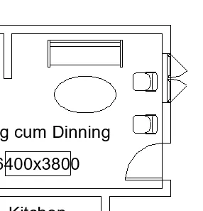
- Step 10: Select the table we want to place , here table ellipse is selected for living .
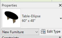
- Step11: Plcae the table in the required position in the living room.
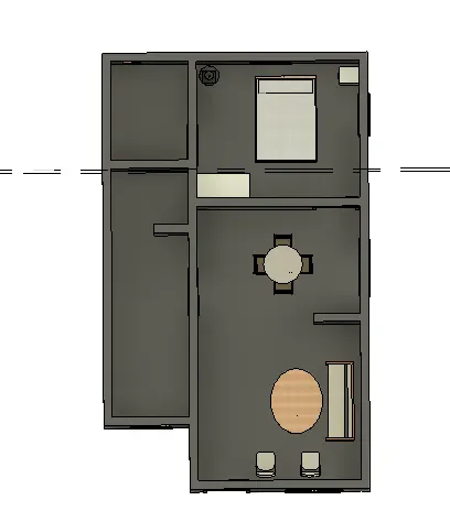
- Step 12: similarly add the sofa and chairs
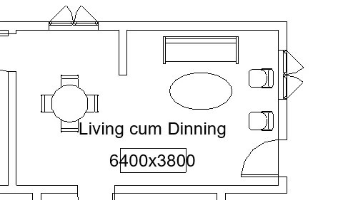
- Step 13: Similarly place table with chair in the dinning area.
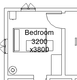
- Step 14: Similarly place bed in bedroom, cabinet is placed,floor lamp ,dresser is placed.
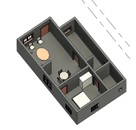
Result: The components are placed in the room.