Creating Levels, Grids, Layout and model elements for a residential unit using REVIT
AIM : TO START WITH BASIC MODELLING OPERATION FOR AND RESIDENTIAL BUILDING PROJECT
INTRODUCTION : IN THIS CHALLENGE WE ARE ABOUT TO KNOW HOW TO START PROJECT BY USING FOLLOWING COMMANDS -
- PROJECT INFORMATION
- GRID AND LEVELS
- ARCHITECTURAL WALL
- TAG ROOM/UNITS
- DIMENSIONS
- ADD DIFFERENT MODEL ELEMENTS
ANSWERS :
1. BIM - BUILDING INFORMATION MODELLING
- BIM is a process supported by various tools, technologies and contracts involving the generation and management of digital representation of physical and functional characteristics of places.
- Building information models are computer files which can be extracted ,exchanged or networked to support decision making regarding a built asset.
- BIM software is used by individuals, businesses and government agencies who plan, design,construct,operate and maintain diverse physical infrastructure such as water ,refuse, electricity, gas, communication utlities roads,railways, ports and tunnels.
- Uses of BIM goes beyond the planning and design phase of project,extending throughout the building life cycle.
- The supporting processes of building lifecycle management includes cost management, construction management, project mangement, facility operation and application in green building.
----------------------------------------------------------------------------------------------------------------------------------
2. CATEGORY : A category controls the organization ,visiblity ,graphical representations and the and scheduling options of families within the project.
FAMILY : A family is a grouping of 2D and 3D information that serves to represent a discrete building or documentation element in the project. it defines parametric ,graphical and documentation requirements.
INSTANCE : An instance is an individual representation of a type in the project defined by unique parametric,graphical and documentaion characteristics which makes it unique from other instances in project.
ELEMENTS : Element is a specific representation in a family defined by distinct parametric, graphical and documentation characteristics which makes it unique from other types in the family.
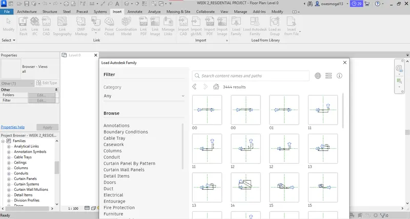
- In the figure below,we have gone to the insert tab and at the left side of screen and also open the whole autodesk family preview such as ceilings,columns and doors etc.
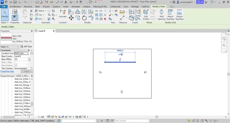
- In figure below we can see the example of categories, i.e Basic wall.if we click on it, it is subdivided into different categories which is called family. And again the families are subdivided into different types based on size which is called elements.
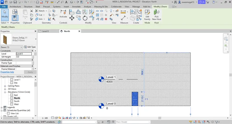
- In the image below door element is added to the wall
-----------------------------------------------------------------------------------------------------------------------------------
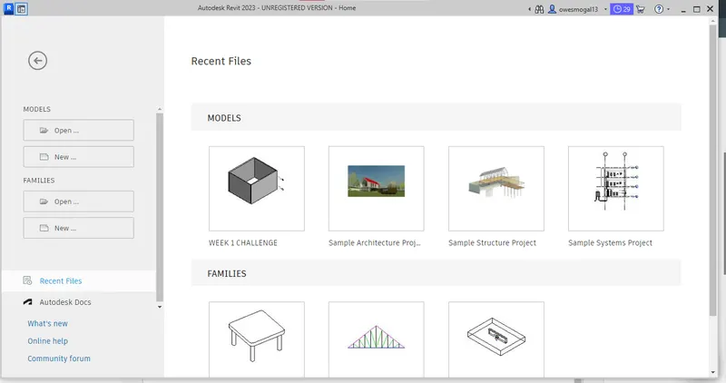
3. In the image below the home page is shown
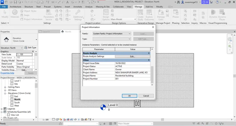
- In the mage below the project information is filled in detail.
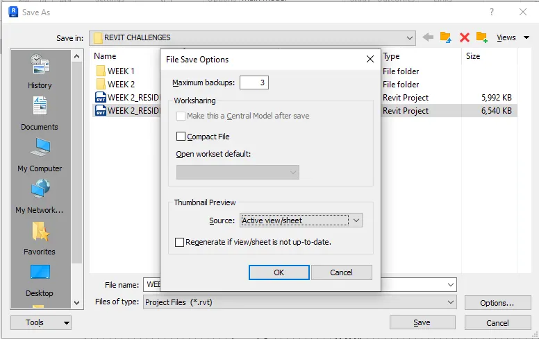
- In the image below the backup od drawing is saved 3 times by selection option tab while saving.
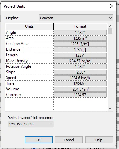
- And also the units were change from metric to imperial from MANGE SECTION > PROJECT UNITS
-----------------------------------------------------------------------------------------------------------------------------------------
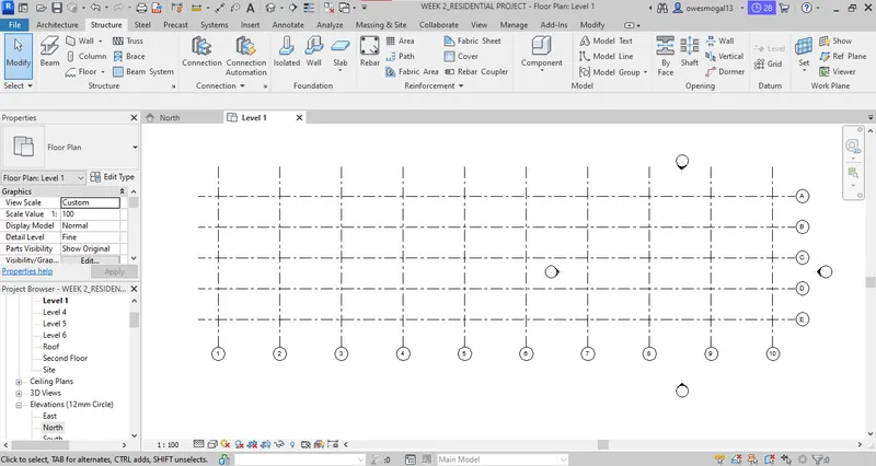
4. LEVELS AND GRIDS :
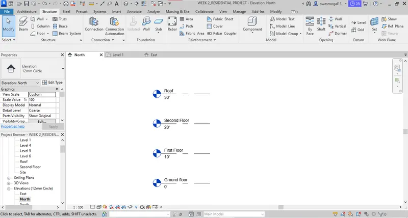
Levels are the most important elements of revit model.whole future modelling depends on how you plan and set your levels in the begining.Levels and grids are the structure of revit model.
- The levels are drawn below at offset of 10ft
Stpes : Structure section > In Datum section , levels > pick line command .
- Grids are drawn at 10' offset distance and at 20' distance offset loangitudinally
Steps : Structure Section > In Datum section ,select Grids > set offet >pick a line command
-------------------------------------------------------------------------------------------------------------------------------------------
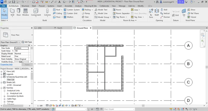
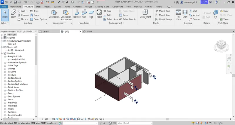
5. RESIDETIAL PLAN :
- The wall are drawn with wall command
- Basic brickwork wall is used for exterior
- Partition wall are used for interior wall purpose
Steps : Architecture section > In wall , Architecture wall command selected > drawn by inputing the desired length for walls
- Ground floor plan
- 3D view
------------------------------------------------------------------------------------------------------------------------------------------
6. DRAFTING
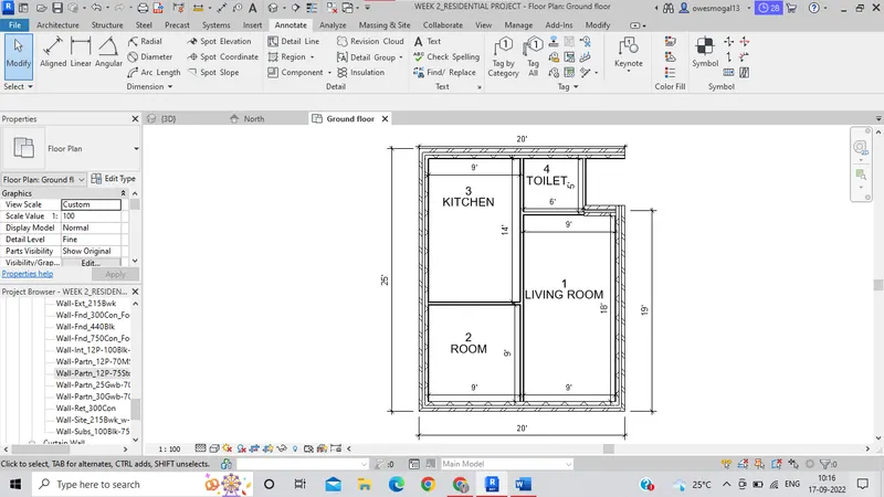
- Dimesion are given with dim linear command to every room, wall and partition as shown in fig below
Steps : Annotate > dim linear command > selcting the edges of wall
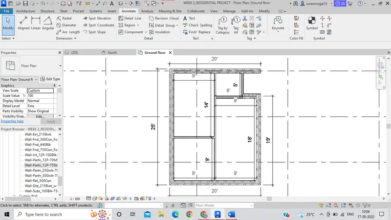
- Components or rooms tag are given in the figure below
Steps : Architecture Section > Room & Area section > Select Tag Room command , the tag and numbering to the rooms were edited accordingly
------------------------------------------------------------------------------------------------------------------------------------------
7. Modifying
- After layout is completed and drafted then GO TO INSERT section
- From insert section autodesk familes was open and various elements such as door, window, chair etc were added
Steps : Insert Section > Load Autodesk family > add reuired families
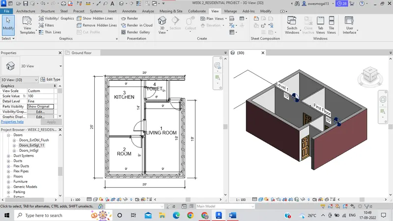
- The door were given to the plan
- Then windows ere added
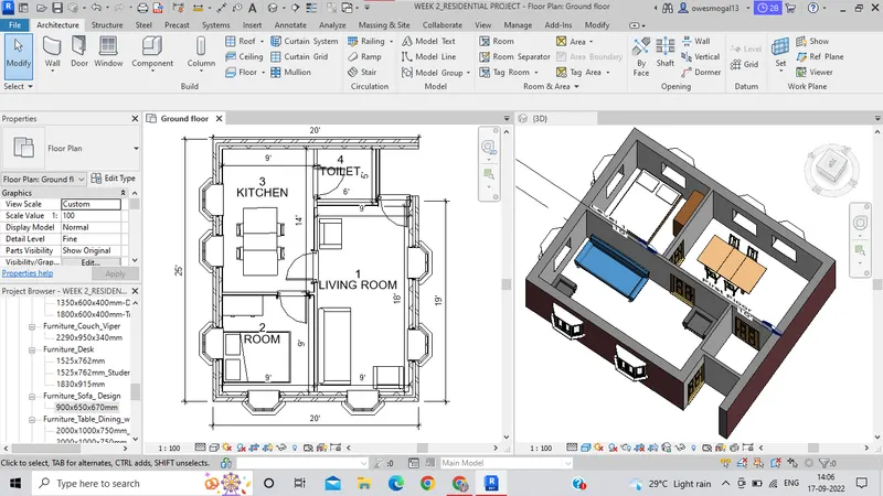
- Then the furniture was added to plan
- After adding Doors
- After adding windows

- Adding Furniture
------------------------------------------------------------------------------------------------------------------------------------------
RESULT :
- The Model Elements are identified from the Library and inserted them to the model.The project is successfully saved for further use.
-----------------------------------------------------------------------------------------------------------------------------------