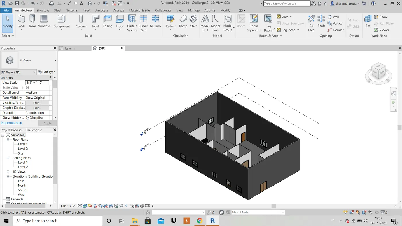
Creating Levels, Grids, Layout and model elements for a residential unit using REVIT
1) What is BIM? Summarize the features of BIM and benefits of using BIM over 2D CAD tools.
Ans :- BIM is nothing but Building Information Modeling. BIM helps Architectural, engineering and construction professionals to improve the way they design, construct and opeate using tools which are more useful and increases efficiency. It enables data sharing about building to all parties and any party can change the required changes.BIM allows sharing of information through a mutually accessible online space known as common data environment (CDE). Using this changes can be made at all stages of building, from starting to operation and even renovation and renewals. BIM levels starts with 0 and go upto 3D,4D,5D and even 6D BIM. The purpose of these levels is to gauge how effectively, or how much information is being shared and managed throughout the process. Computation is also a major discussable aspect, it mainly involves energy evaluation,load calculation and schedule planning.
Benefits of using BIM over 2D CAD tools is that in BIM we can even work in 3D, 4D, 5D or even 6D Whereas in 2D CAD only 2D can be viewed. BIM is the newest one out of BIM and CAD, it has even more advanced features. is The major benefit is that BIM is multi user interface whereas CAD is single user interface so, any changes can be done easily and accuratley throughout the project. Resource tracking also acn be done in BIM i.e; one can figure out how much resources are required.
2) Understand the concept of Categories, Families, Elements, Instances in Revit. Go to Insert Tab, choose a category. Pick a family and element. Understand the instances and insert it to Revit model.
AIM: To pic familiy and element from category and insert it to revit model:
TOOLS USED:
- OPEN
- INSERT
- LOAD FAMILY
- ELEMENT
PROCEDURE:
step-1:
- open the file created already.
- select insert pane
- click on load family
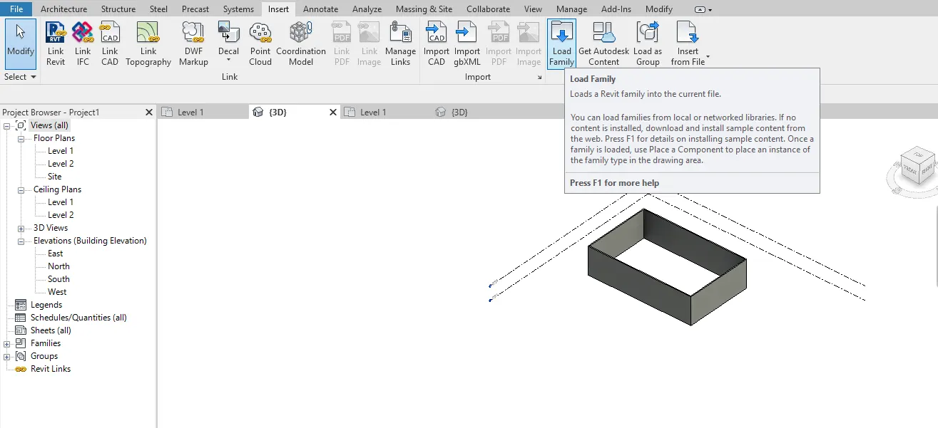
step-2:
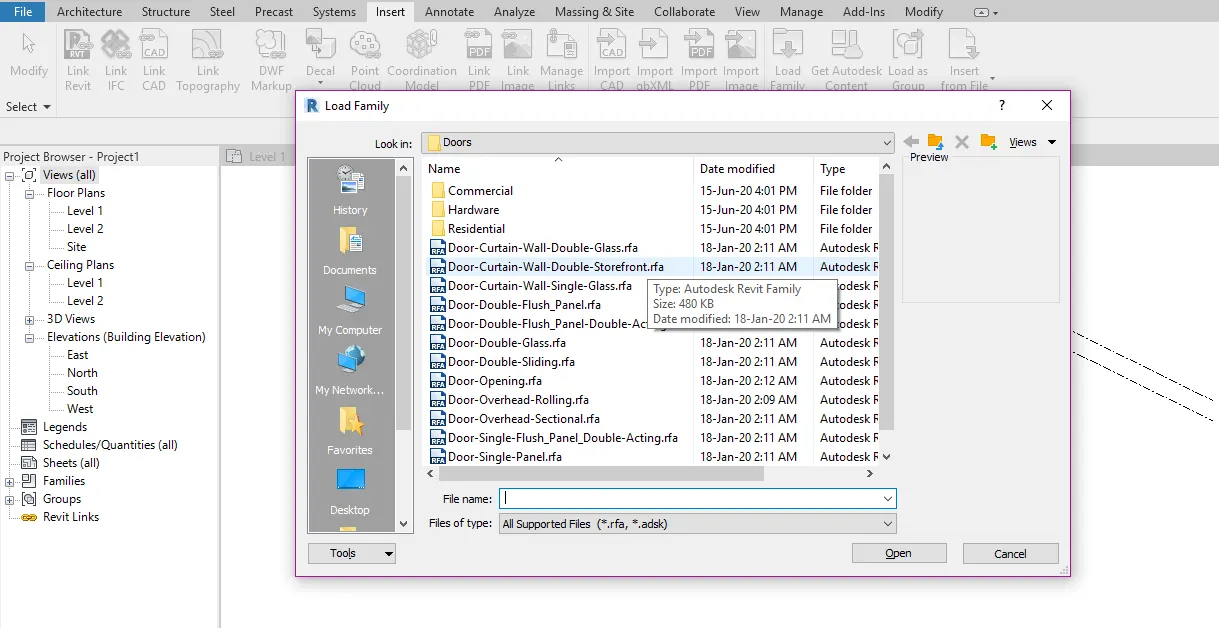
- select the category and selectg the element like doors windows etc.,
- click on the door and select type of door
- insert it in the frame work designed.
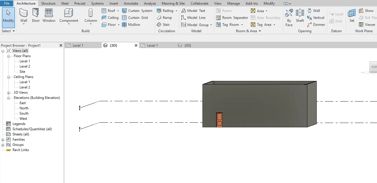
RESULT: the concept of families,elements has been acknowledged. Families and elements has been picked and inserted in revit model.
3) Setting up a Project – Open a project file with architectural template. Save the file with appropriate name. Set up the project units to Imperial / Metric based on your convenience of modelling. Complete the project information under Manage tab. Set up the maximum backups for project file to 3.
Ans :-
Aim: Setting up a project , opening and saving the file with appropriate name, and completing the project information under the manage tab with maximum backups for project file to 3
Tools used : Manage tool bar,Project information,Architectural template,Save option
Procedure:
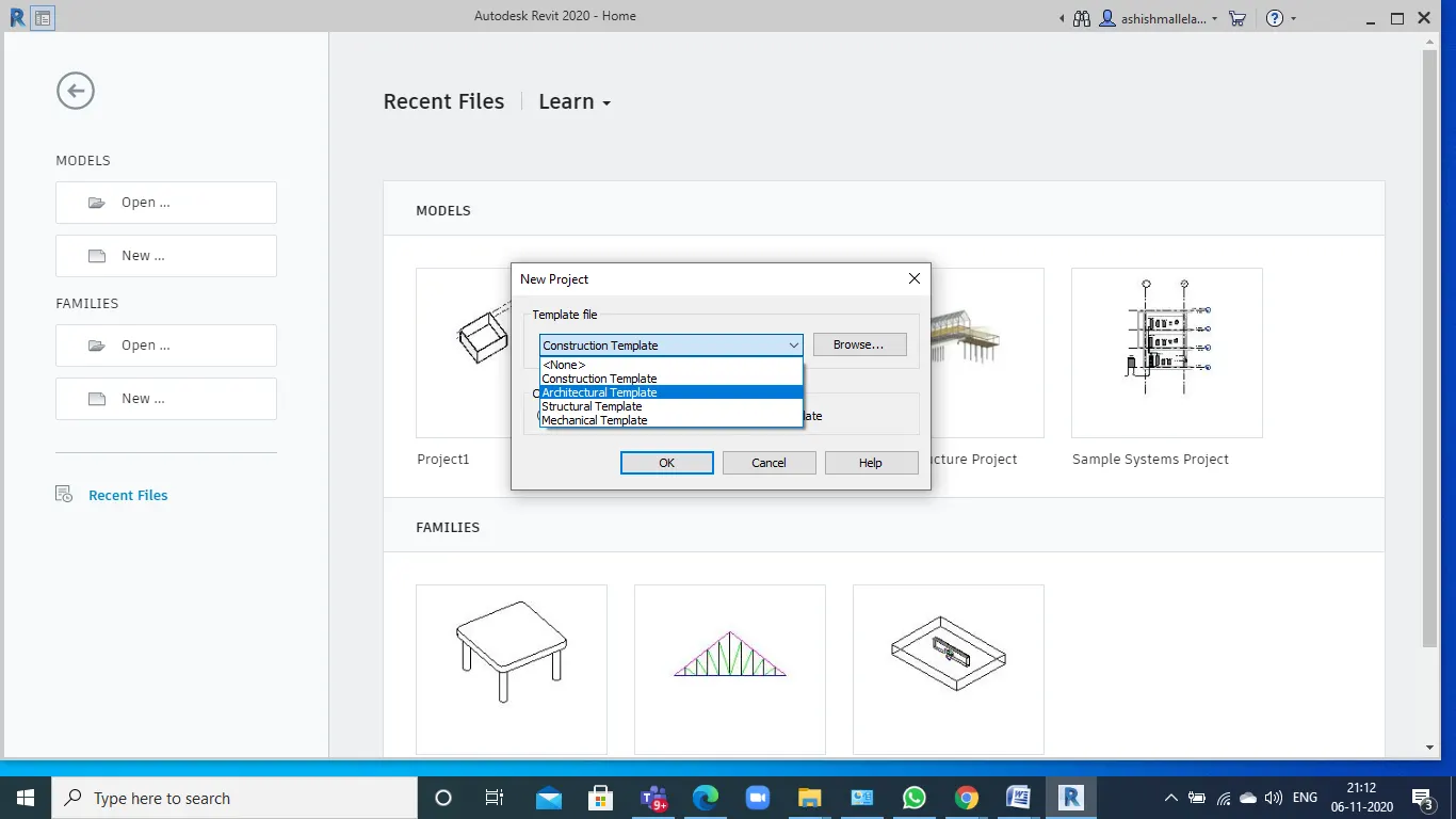
- Open the new project with architectural template .
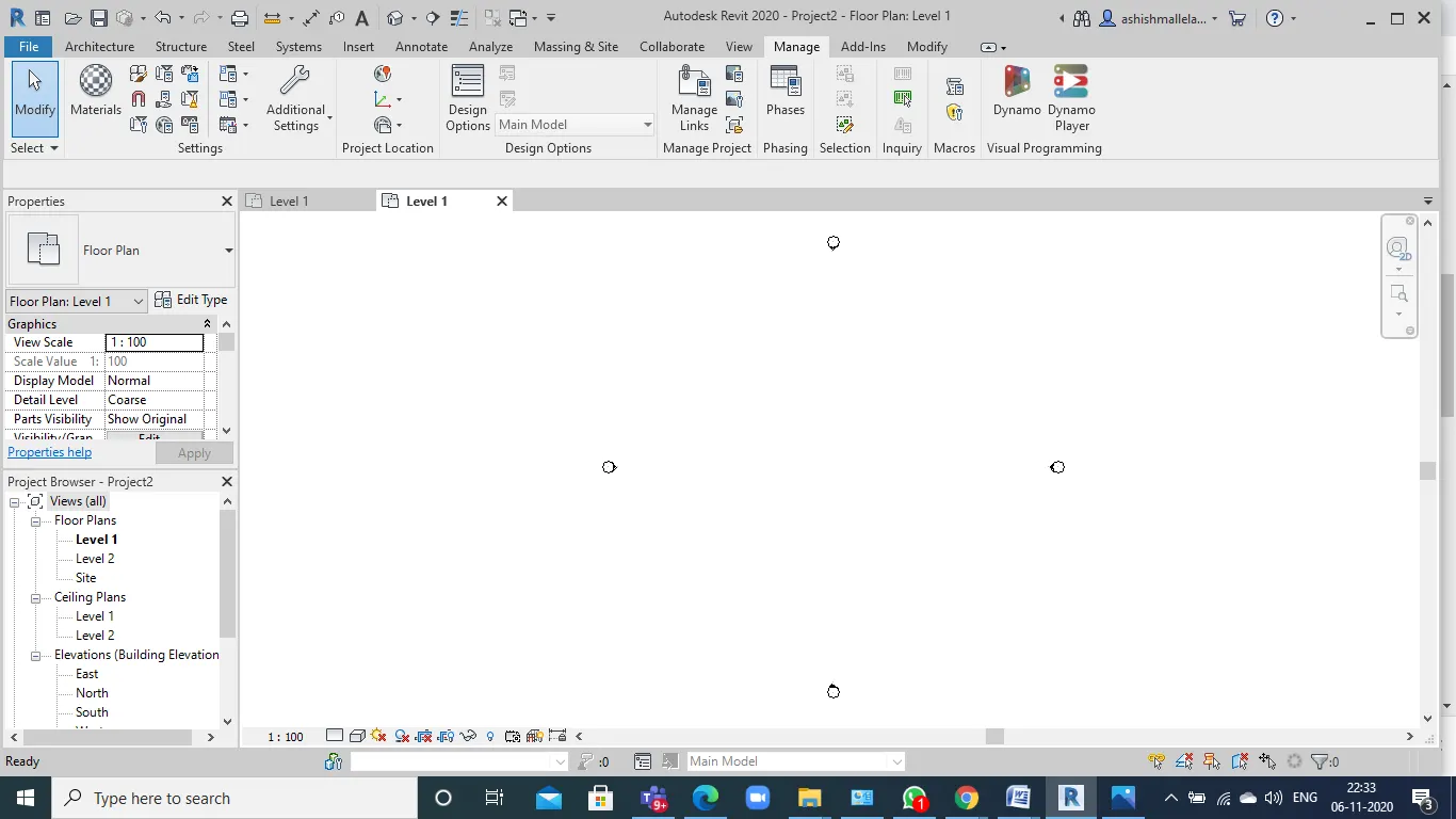
- Then once the project is open, click on the manage tab.
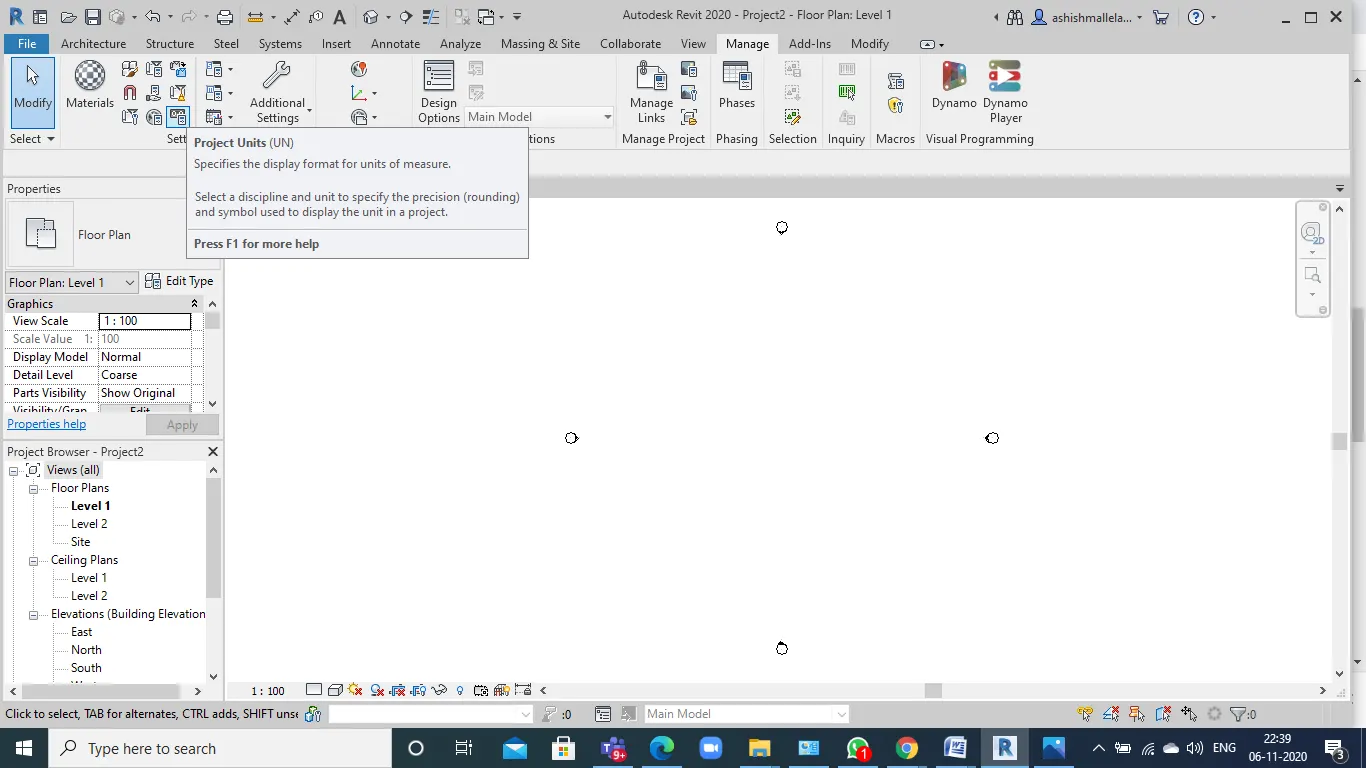
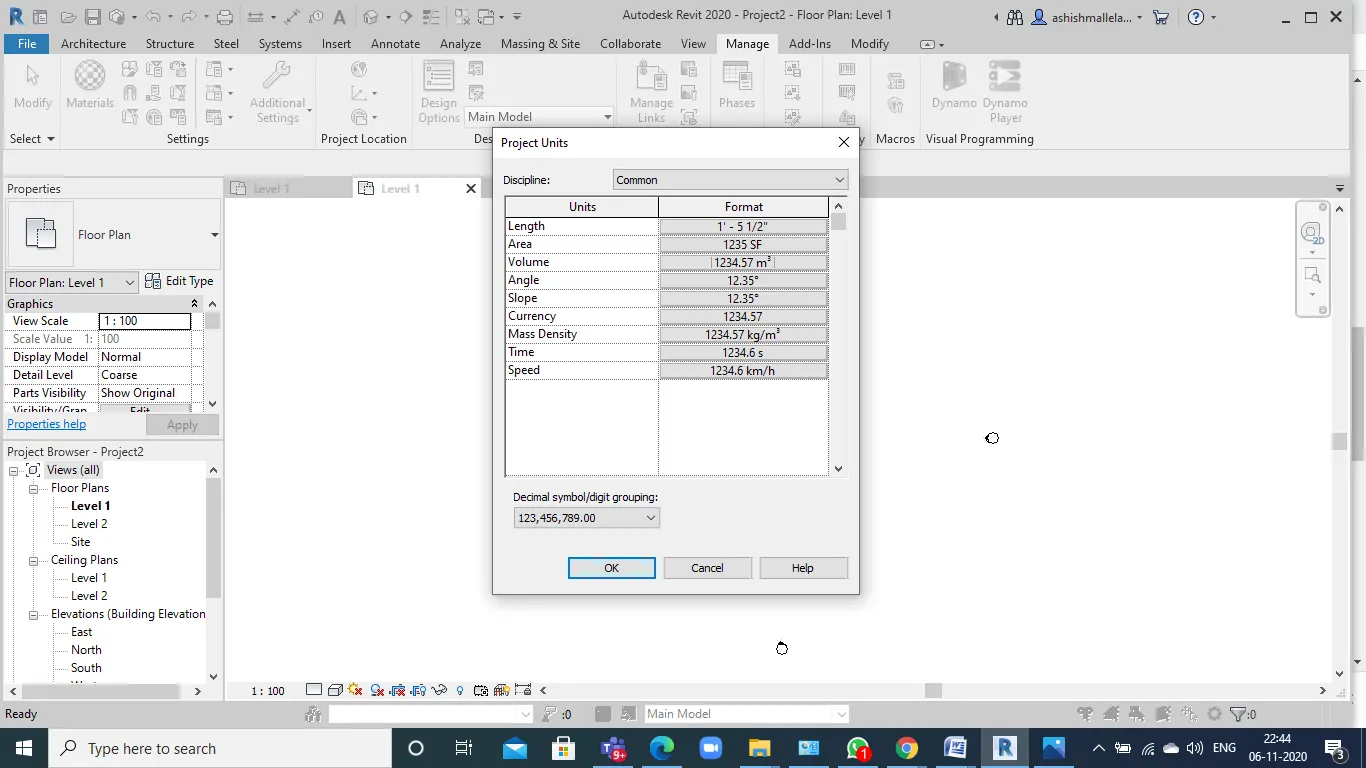
- Then click on the project units, to change the units according to the requirement.
- Once u change the units click on ok.
- click on project information icon
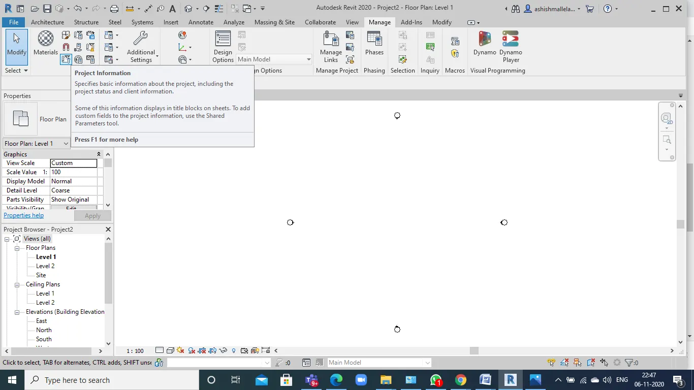
.
- Fill in with proper information regarding the project . press okay after filling everything .
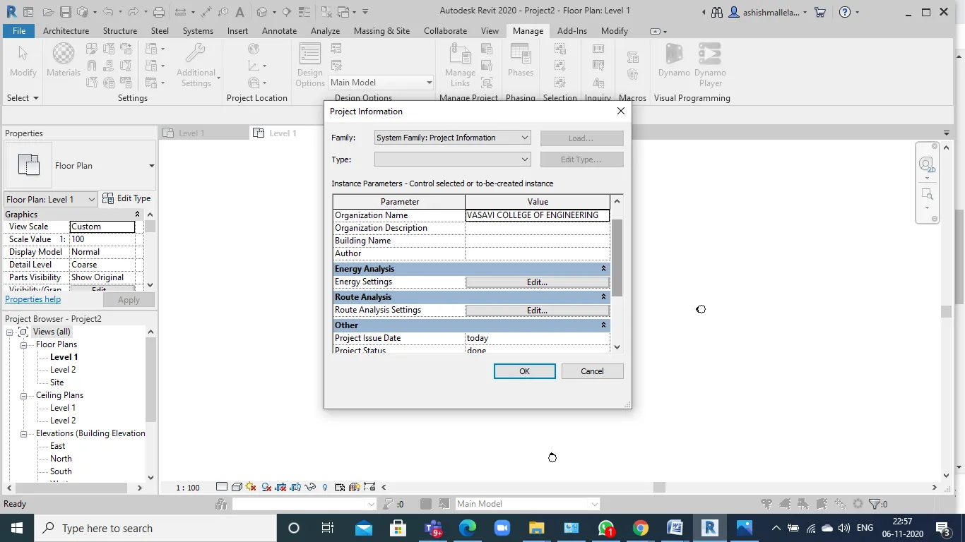
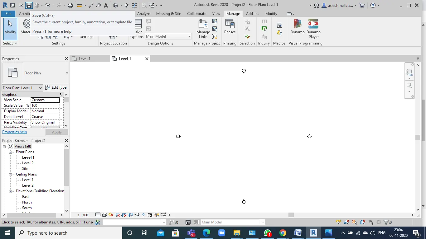
- Now Click on save to save the file .and assign a name for your file.
- Click in the option button, where you are given an option for backup. Set up the maximum backups for project file to 3.
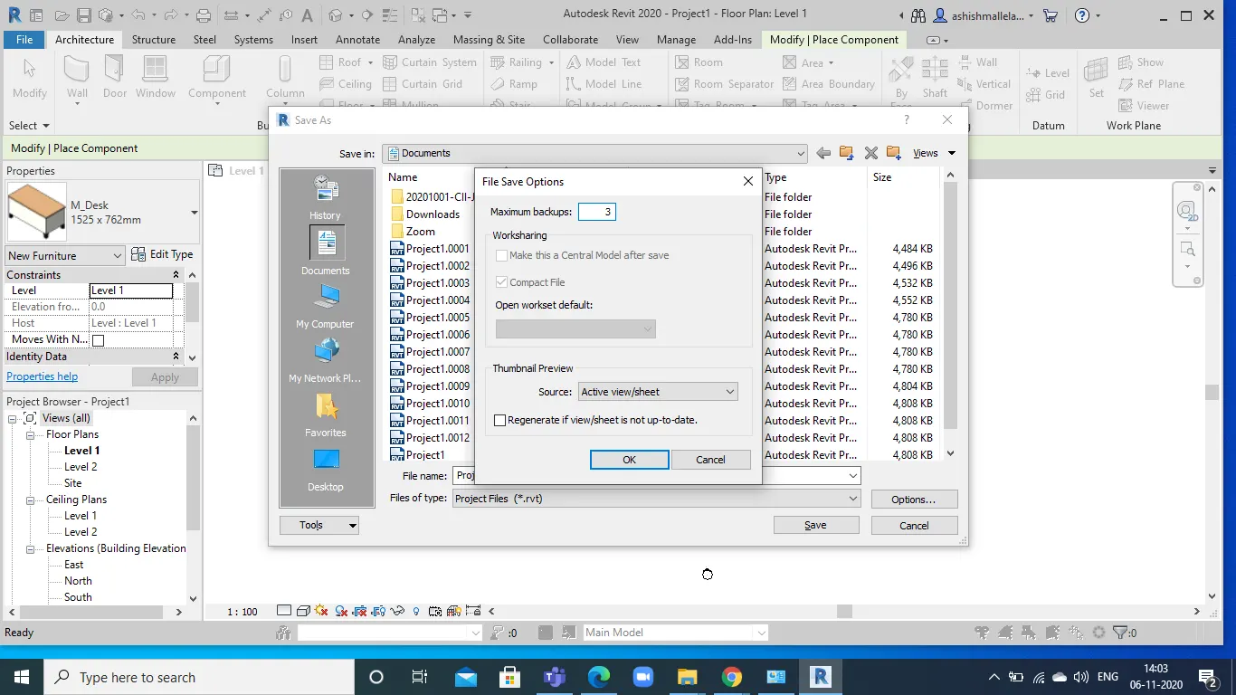
Result: The requirements are done using revit model.
4) Understand the concept of Levels and Grids. Follow the naming and conventions. Create the following Levels: ( Convert to metric equivalents if metric is your units)
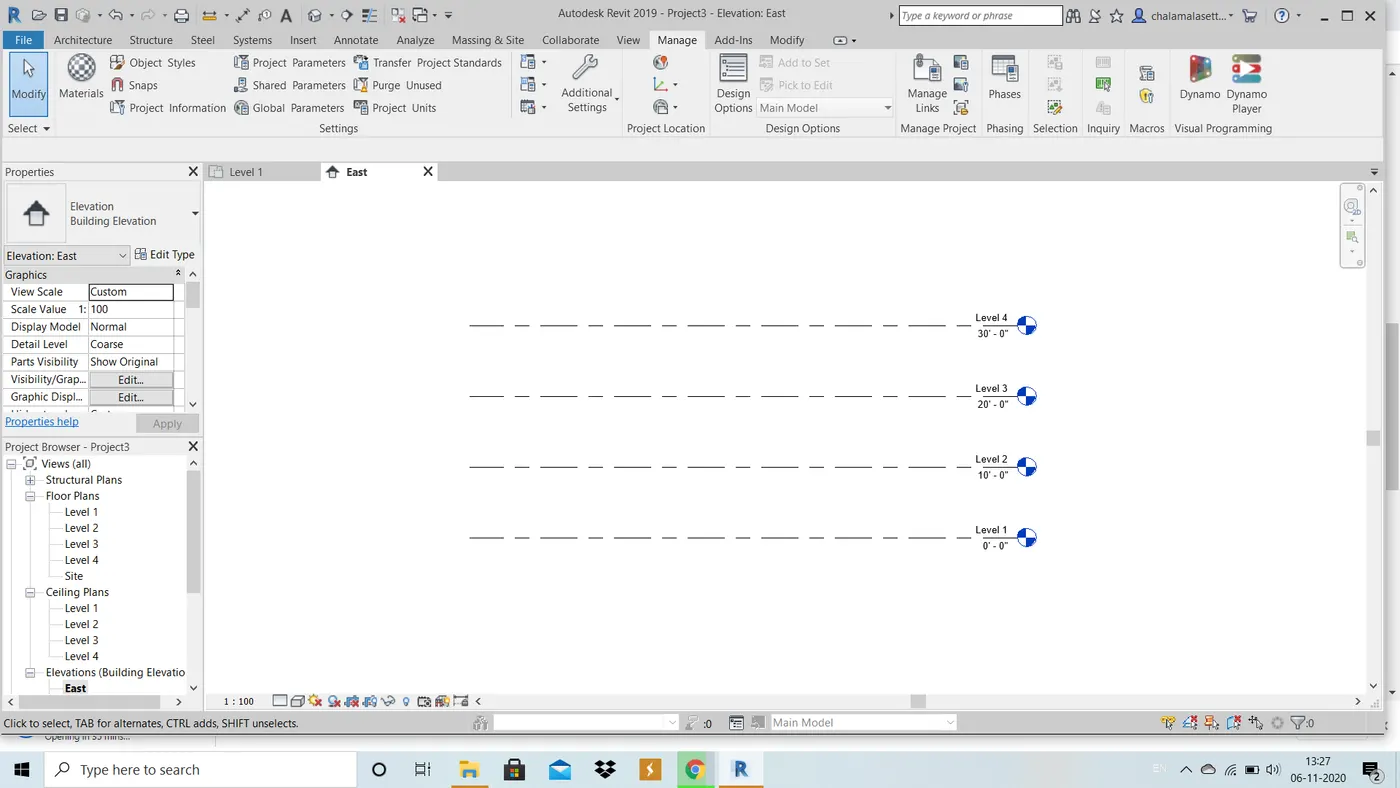
Ground Floor @ 0’
First Floor @ 10’
Second Floor @ 20’
Roof @ 30’
AIM : To create the following levels:
Ground Floor @ 0’
First Floor @ 10’
Second Floor @ 20’
Roof @ 30’
To create grids :
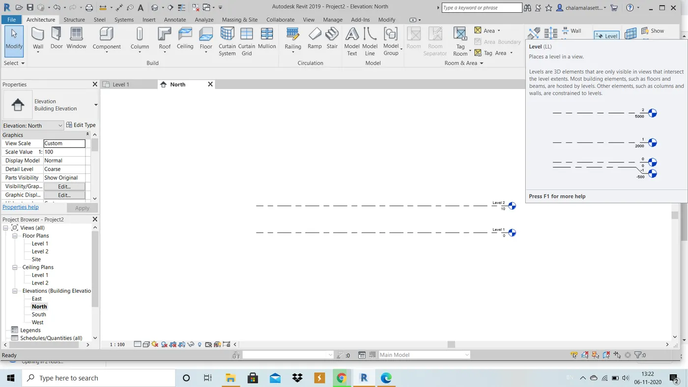
Transverse Grids A, B,C,D, E @ 10’ spacing
Longitudinal Grids from 1 to 10 @ 20’ spacing
TOOLS USED : Architecture, grids, levels.
PROCEDURE :
1. Create a new project file of architectural template, change units to feets and inches.
2. In the project browser, go to elevation views and and select any direction.
3. In the architecture tab, click level option and create a level by typing the required offset from the nearest level.
4. Now click on plan view and clickon grid tool which is below level option and create grids by setting required offsets transverserly and longitudinally.
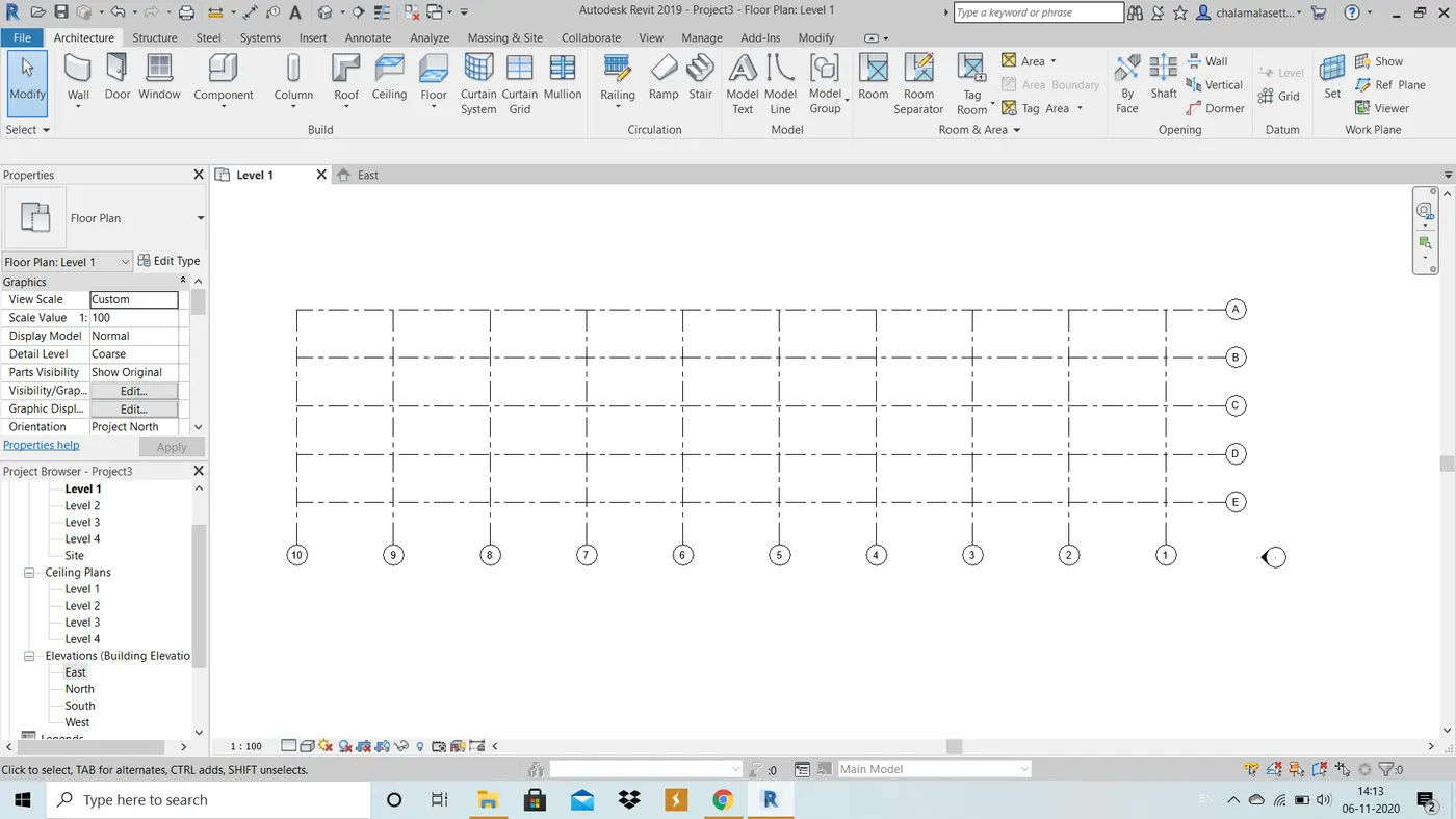
RESULT : The grids and levels are successfully drawn.
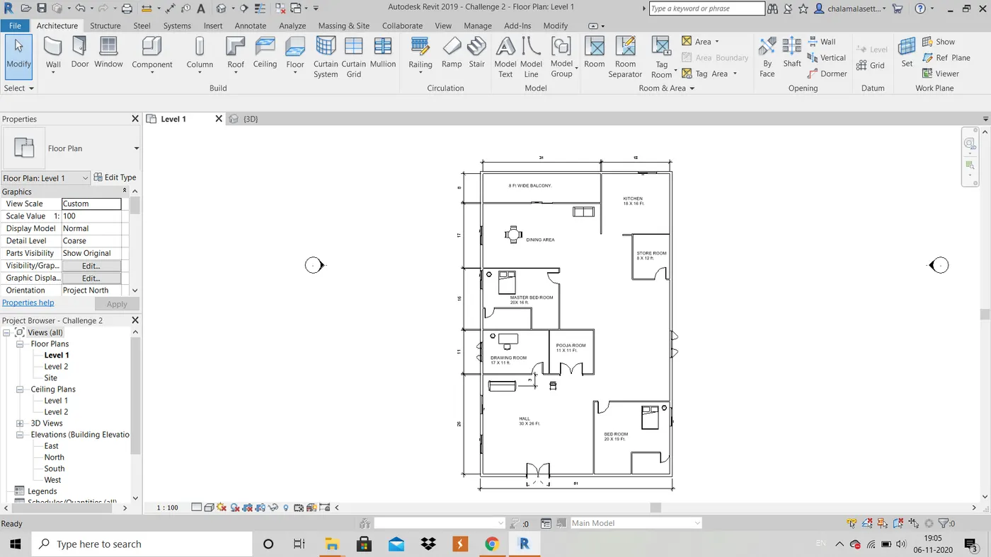
5) 3D modelling of residential unit – From looking at your house / or a place you aspire. Create a conceptual layout of the residential unit. You can measure using a tape or
you can access your residential plan to create a similar layout.
AIM : 3D Modeling of a residential house, to create a conceptual layout of the residentrial unit.
TOOLS USED : Architecture, wall, view, default 3D view.
PROCEDURE :
1. Open a new architectural template
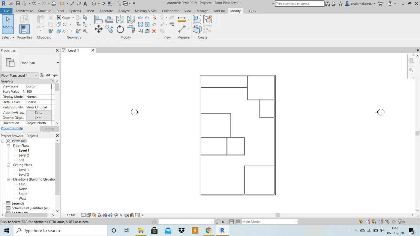
2. Using wall tool in archtecture menu, draw otter boundary of the residential unit.
3. Complete the layout using different types of walls for partition walls and interior walls.
4. Create floor using floor tool and set boundaries for floor.
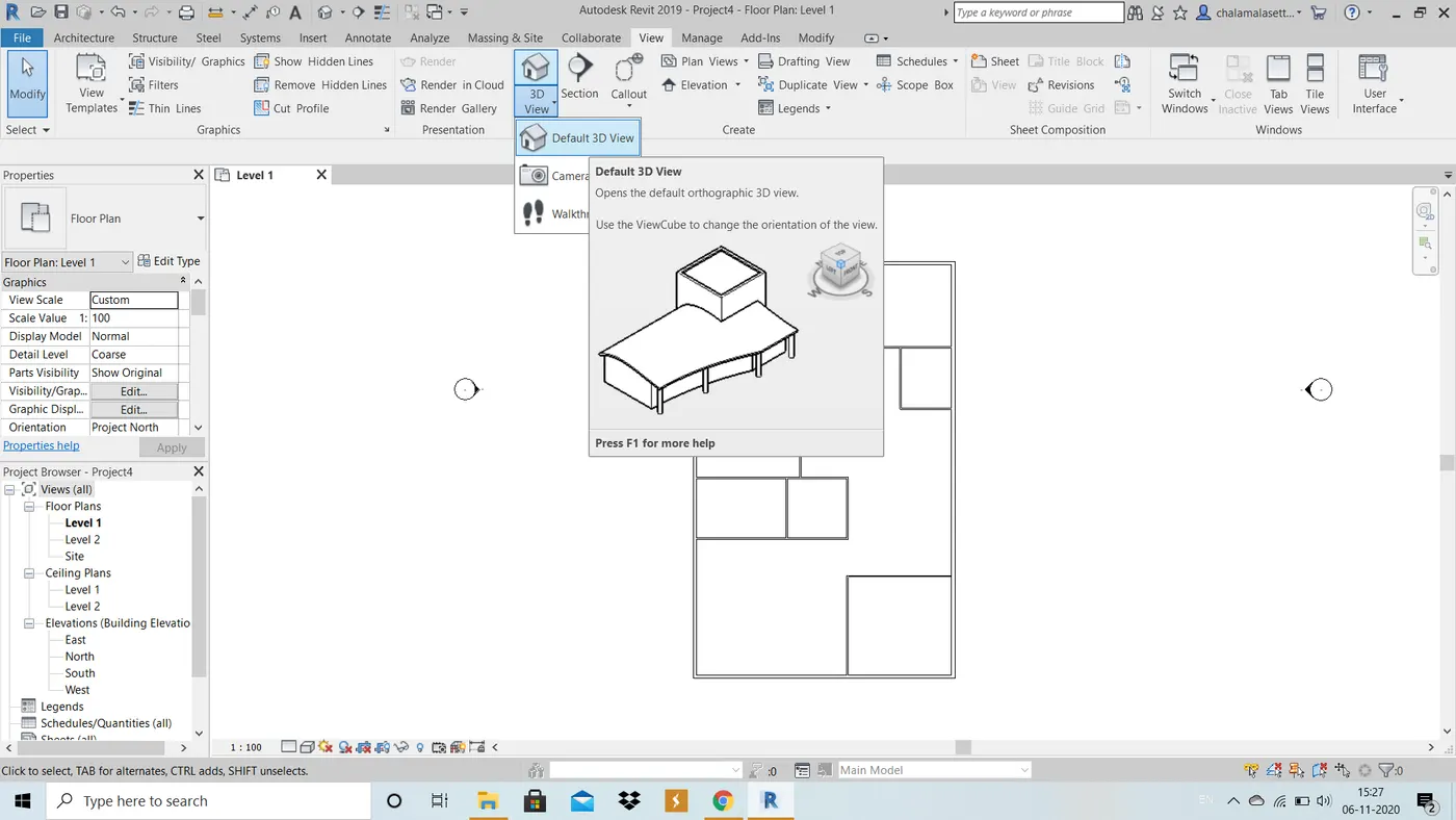
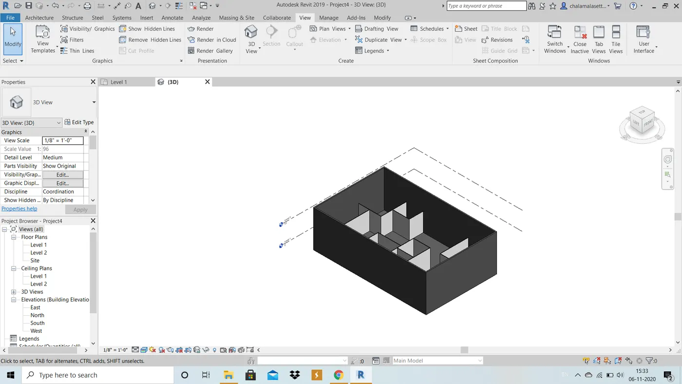
5. Click on 3D view in view menu tab.
RESULT : The required 3D layout of residential unit is created.
6) In the layout created draft the level of details you are planning to include – Dimensions of room, components you plan to add in the residential unit.
AIM : To add details such as dimenions of room and components to add in reisdential unit.
TOOLS USED : Annotate, Linear .
PROCEDURE :
1. In the previously created project, go to Linear option in annotate menu bar and fix a point drag until the other line to get the measurement.
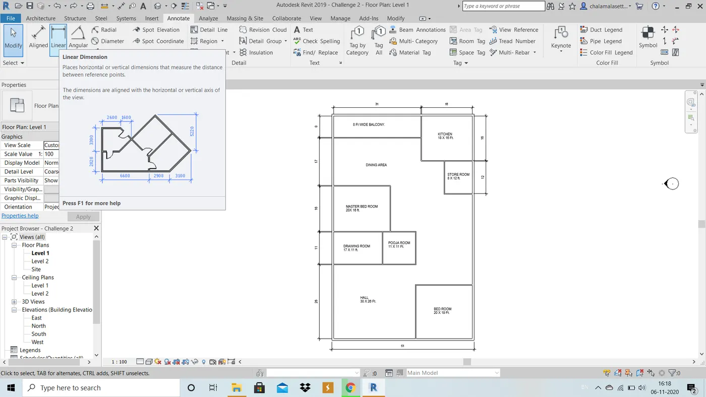
2. Click Text option in annotate to write all the measured room dimesions.
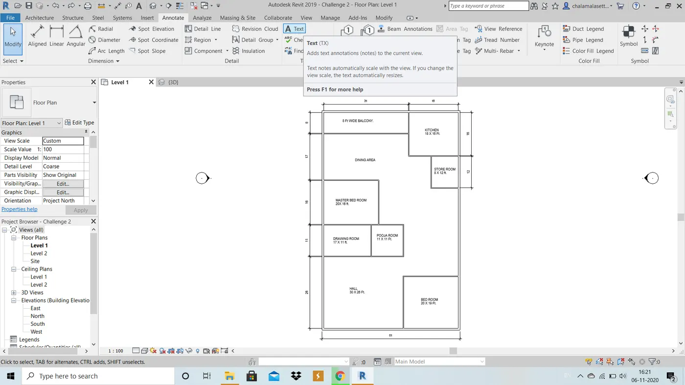
RESULT : The required details are added to the project.
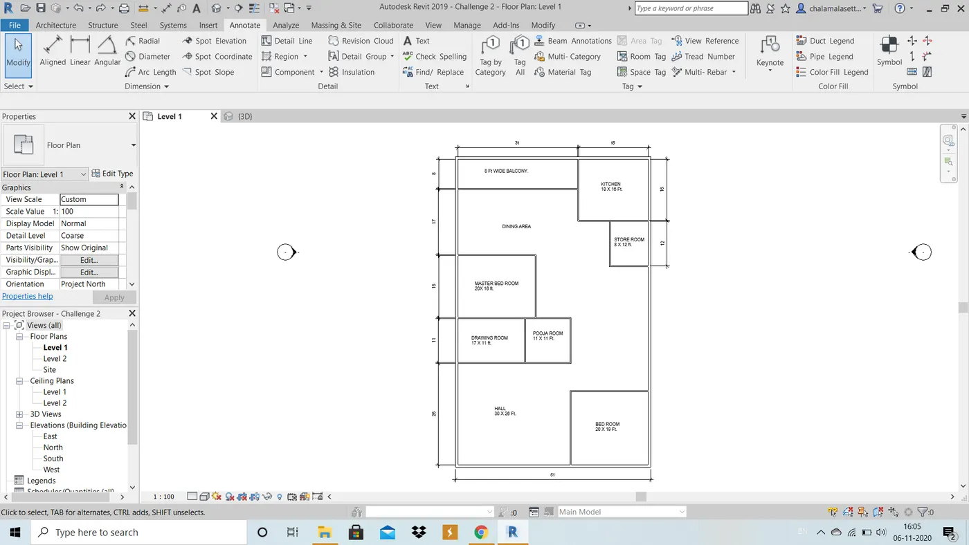
7) Identify the residential model elements such as Door, Windows, Tables, Chair, Couch, Bed, Lamps from the library and insert them to the model .
AIM : To add residential model elements such as door, wondows, tables, chair, couch, bed, lamps from library and insert them to model.
TOOLS USED : Load family, Insert tab, view menu, architecture menu, doors, windows, component tools.
PROCEDURE :
1. In the architecture tab click on doors and windows and select the place wherever they must be added.
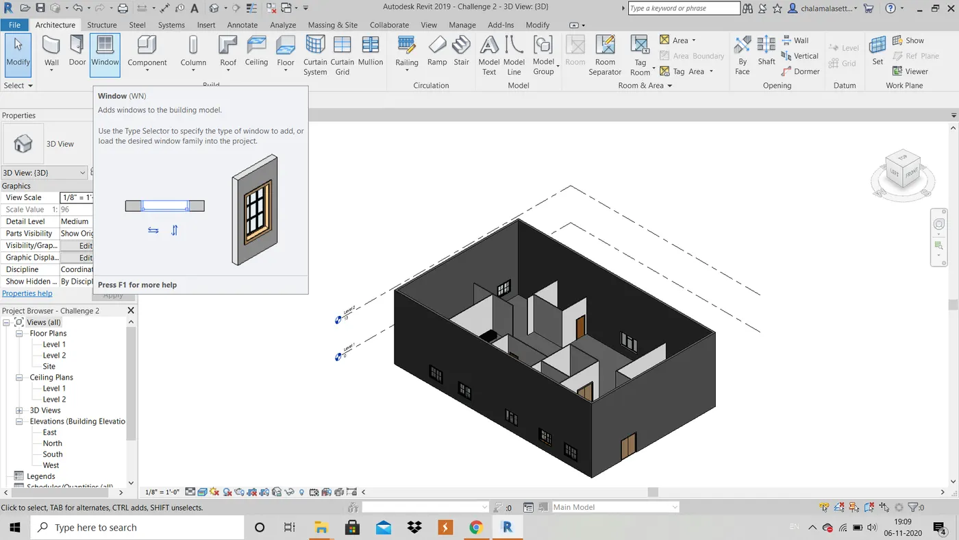
2. Click on load family in the insert menu, load required elements, click ok .
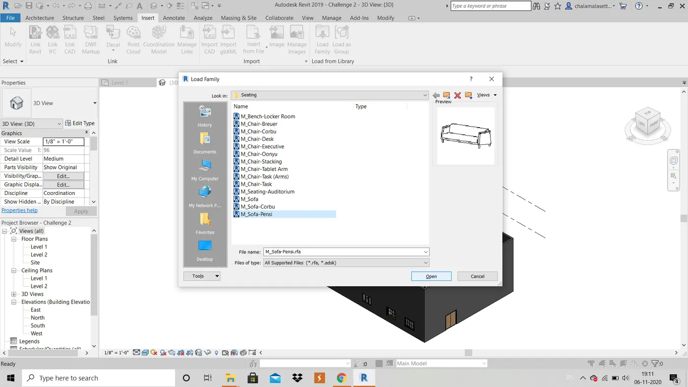
RESULT : The required elements are added successfully.
PLAN VIEW :
3D VIEW: