Creating Levels, Grids, Layout and model elements for a residential unit using REVIT
1) What is BIM? Summarize the features of BIM and benefits of using BIM over 2D CAD tools.
BIM is Building Information Modelling which is a visual representation of a building with its full data and funstions of the building. The main features of BIM are easy access to information of the the building model and a complete representation of the project can be viewed. BIM is more advantageous over 2D CAD tools as everything including estimation, analysis and entire accesories of the building can be included which is the whole representation of the project.
2) Understand the concept of Categories, Families, Elements, Instances in Revit. Go to Insert Tab, choose a category. Pick a family and element. Understand the instances and insert it to Revit model
Aim: To understand the concept of Categories, Families, Elements, Instances in Revit and to insert the elements in the revit model.
Introduction: The concept of category is that it is a graphical representation of a group of families and the families contains the group of types of elements which can be inserted into the model. The concept of category and families can be simply represented by door
Door - Category
Commercial,Residential etc., - Family
Single door ,Double door etc., - Instances or elements
size of doors like 30" x 72" - Types
Steps:
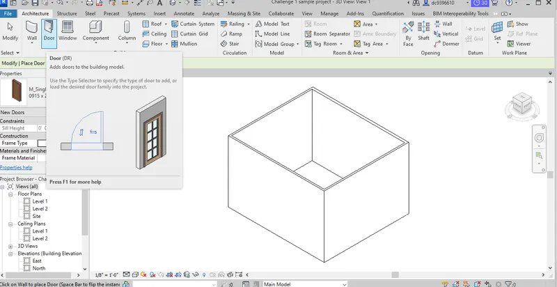
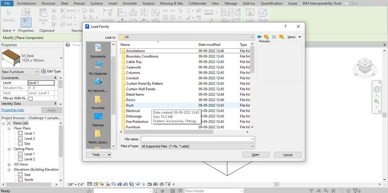
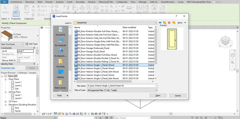
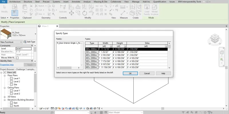
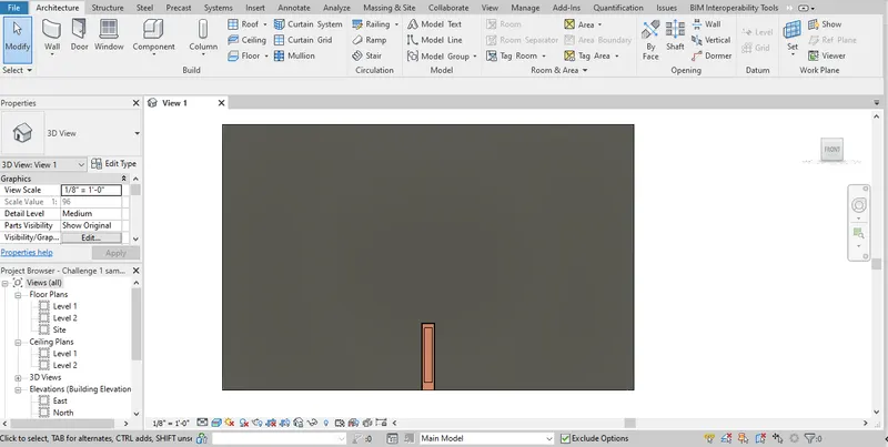
- To insert door in the Architecture ribbon menu door option is selected
- Then Load family command is selected
- Then In load family door option is selected and residential family is selected
- From the no of door elements present in the residential single door element is selected and inserted into the model wherever needed.
Result: Thus a single type wood residential door is inserted into the model sucessfully.
3) Setting up a Project – Open a project file with architectural template. Save the file with appropriate name. Set up the project units to Imperial / Metric based on your convenience of modelling. Complete the project information under Manage tab. Set up the maximum backups for project file to 3
Aim: To Open a project file with architectural template and Save the file with appropriate name and to complete the project information under manage tab and to setup a maximum backup files to 3.
Introduction: Setting up a project with required template is mandatory for model creation and creating the project information under the manage tab is the first step in the model creation as it is necessary to have project information first to avoid confusion. Then setting backup files is important to avoid loss of model work created. Upto 99 backup files can be created.
Steps:
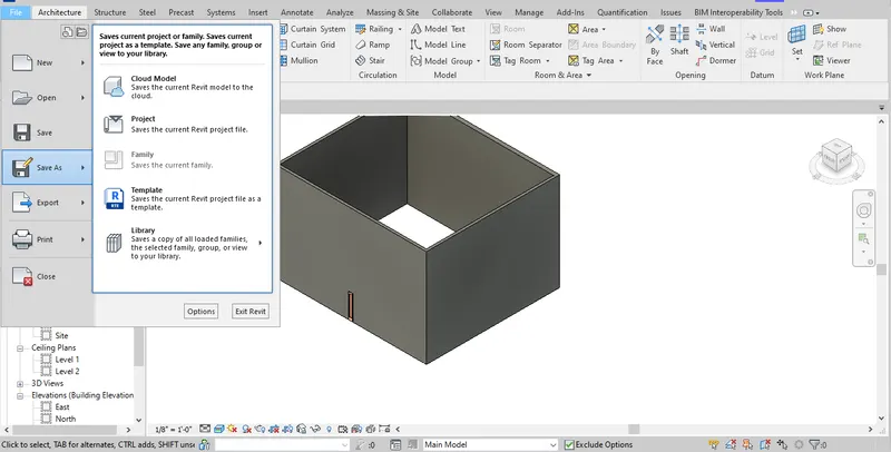
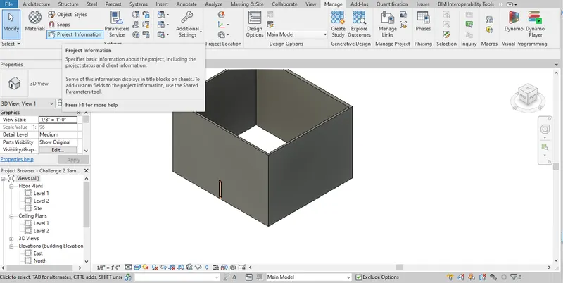
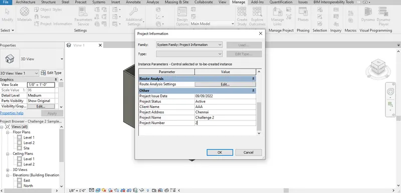
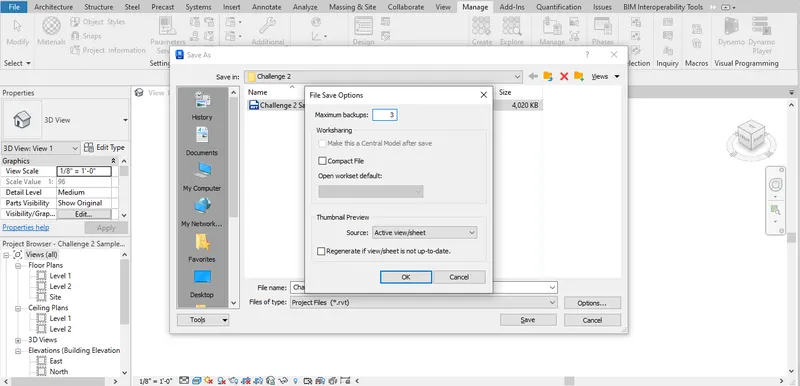
- Initially after opening the project to save the file as project file option is selected
- Then in the save as option project option is selected and the project can be saved wherever required
- Then for providing project information Manage command is selected
- Furthermore Project Information option is selected and the necessary project information is entered and saved
- Then finally for selecting number of backup files options command is selected while saving the project and the number of back up files can be entered, 3 is selected in this case.
Result: Thus a project file is created with the required template, project information and number of backup files is set sucessfully.
4) Understand the concept of Levels and Grids. Follow the naming and conventions. Create the following Levels: ( Convert to metric equivalents if metric is your units)
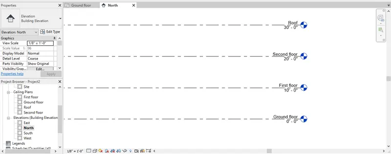
Ground Floor @ 0’
First Floor @ 10’
Second Floor @ 20’
Roof @ 30’
Grids Transverse Grids A, B,C,D, E @ 10’ spacing
Longitudinal Grids from 1 to 10 @ 20’ spacing
Aim: To create levels and grids in the model space as per the requirements given.
Introduction: The height of levels represent the floor levels of the building such as first floor, second floor, etc., and grids represent the centreline drawing of a model which is created for identification of objects and mandatory drawing for field.
Steps:
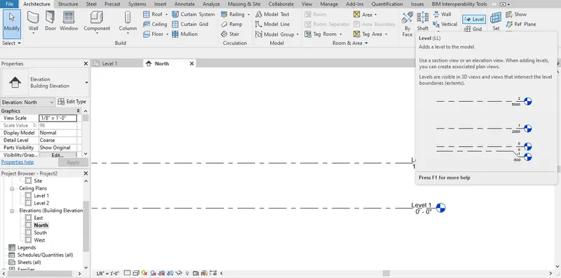
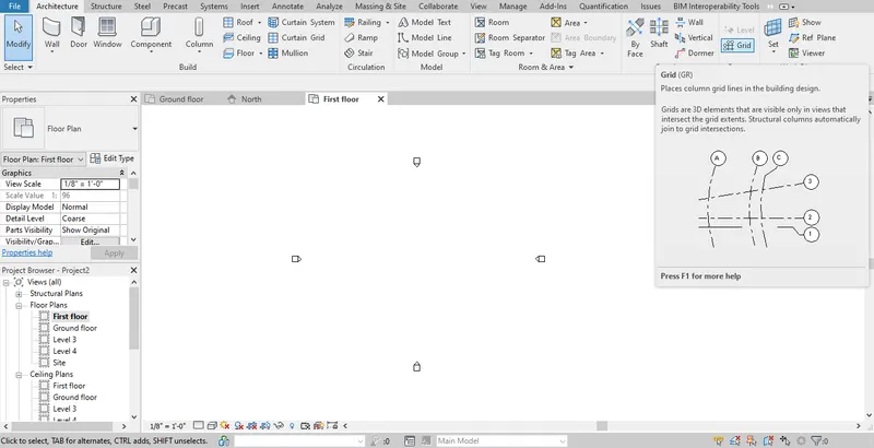
- Initially for creating levels default elevation view is selected as the levels can be created only in the elevation view
- Then after fixing the elevation view level option is selected for creating level
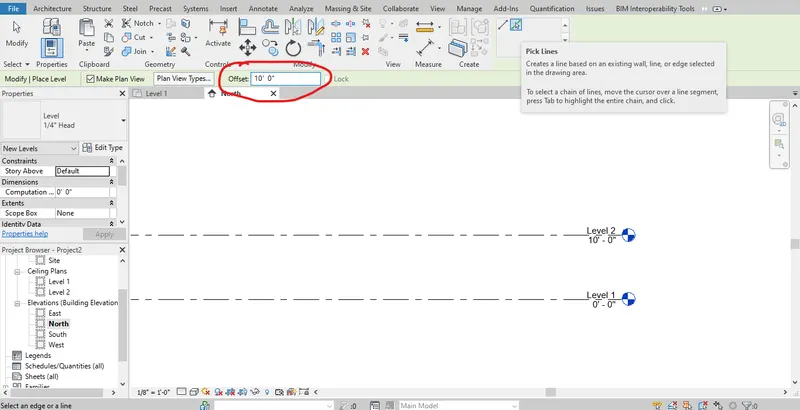
- In that pick line option is selected and offset is fixed at 10' as per requirement and the existing levels can be selected and offseted.
- The offset is repeated till the required levels are created and the levels are renamed by double clicking on the level name and the names are provided as per the requirement
- After level grids are created at the floor plan view
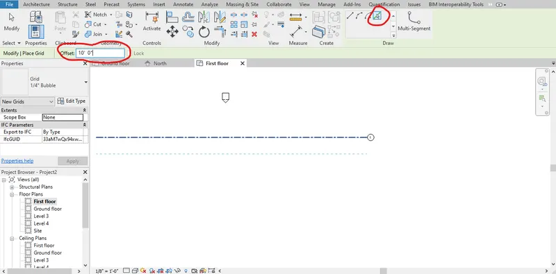
- For grid creation grid option is selected in the ribbon tab and using the line command grid is drawn horizontally
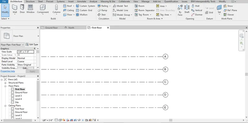
- Then using the pick line command and the offset at 10' grids are created by offsetting the previous grid line created till 5 grid lines are created and the grids are renamed as A,B,C, et., by double clicking the name.
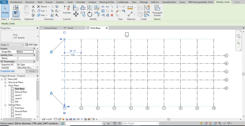
- Then same procedure is repeated for vertical grid line creation till 10 grid lines with offset of 20' and are renamed as 1,2,3, etc.,
Results: Thus levels and grids are created in the model sucessfully as per the requirement.
5) 3D modelling of residential unit – From looking at your house / or a place you aspire. Create a conceptual layout of the residential unit. You can measure using a tape or
you can access your residential plan to create a similar layout.
Aim: To create a conceptual layout of the residential unit as per the required sizes.
Introduction: In the process of model creation Architecture Imperial template is used and 2BHK is considered in the model. The model also consists of a seperate wash area for clothes with verandah and a store/pooja room. The sizes of the bedrooms are considered as 11'x12' and 13'x12' respectively. The room sizes are assumed as per the requirement.
Steps:
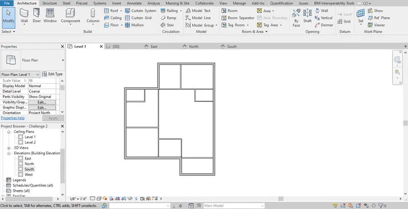
- After setting up the project architecture wall command is selected from the ribbon tab
- Then the type of wall is selected from the properties panel and 8" generic wall is selected in this case.
- Then using the line option the external wall is drawn as per the layout
- Then using the same wall command and line option internal walls are drawn as per the layout of the room placement
- For internal walls from the properties panel internal wall is slected and drawn and the model layout is created
Results: Thus a model layout plan is created sucessfully with Architecture Imperial template.
6) In the layout created draft the level of details you are planning to include – Dimensions of room, components you plan to add in the residential unit.
Aim: To provide Dimensions of room, components to add in the residential unit.
Introduction: After creating the layout annotation of the model is mandatory step to provide details of the room with sizes and to avoid confusion with dimensions of the room and the room tag is probably the most important part of the layout to provide clear view of the plan with the sizes.
Steps:
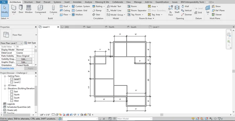
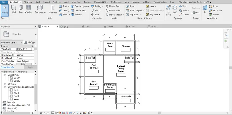
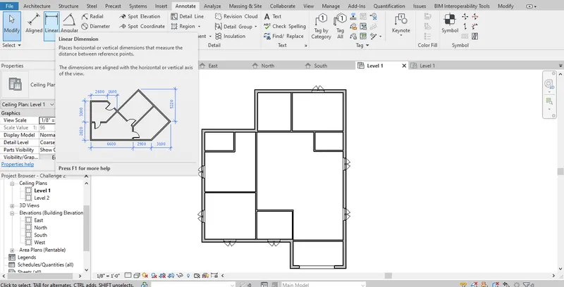
- To provide dimensions to the room Annotate command is selected from the ribbon tab
- Then using the linear option dimensioning is done
- It is done by selecting from end to end of the walls of the room and the ends are selected carefully to avoid miscalculation of the room created
- Similar to linear there are several other options like aligned,radius for particular usage of annotation
- Then room tags are provided by room command in the ribbon tab
- After selecting the room command seperate rooms are selected and are named.
Results: Thus dimensioning of the layout and room tag is done sucessfully.
7) Identify the residential model elements such as Door, Windows, Tables, Chair, Couch, Bed, Lamps from the library and insert them to the model . Save the project for use for Assignment 3
Aim: To provide elements such as Door, Windows, Tables, Chair, Couch, Bed, Lamps from the library for detailing purpose of the model.
Introduction: After the model creation elements are added to the building to provide a clear view of the plan. It is done for particular usage of particular and for aesthetic purpose. For the whole representation of the project adding of elements is mandatory.
Steps:
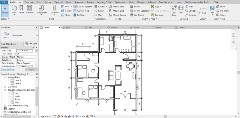
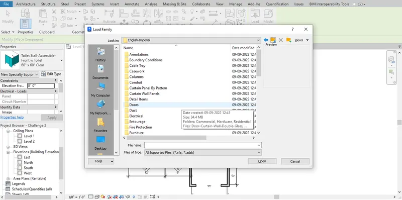
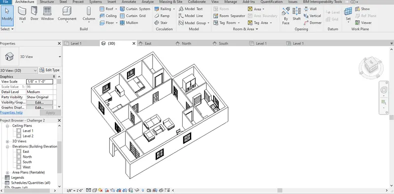
- For door and windows, the respective commands are selected from the ribbon tab is selected
- Then load family option is selected for providing different types of doors and windows
- Then the required type of doors and window is selected and inserted in the model
- Then for providing furnitures like bed,table etc., and electrical components like washer,Tv etc., is provided by Insert command or place a component option in the ribbon
- After selecting the place a component option in the ribbon load family option is selected
- Different types of families are there for different types of elements like Speciality equipments for washer etc., Hence it is selected as per the requirement and the elements are added.
Results: Thus the elements such as doors,windows etc., are added susessfully to the model layout created.