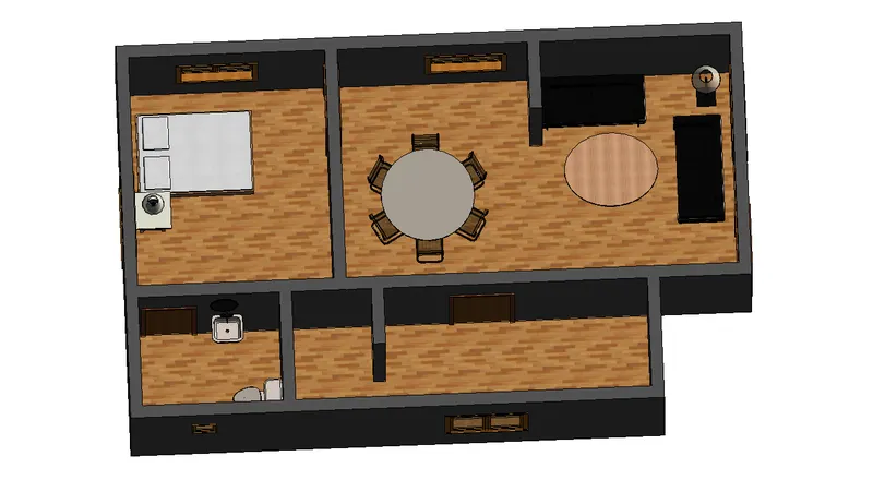
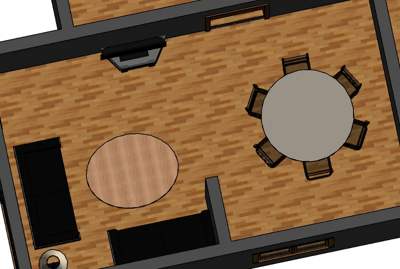
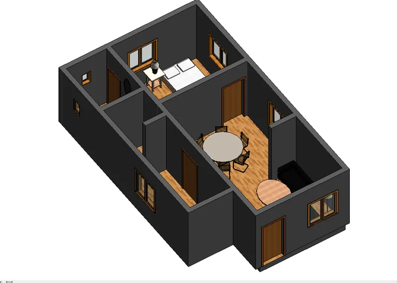
Creating Levels, Grids, Layout and model elements for a residential unit using REVIT
1) What is BIM? Summarize the features of BIM and benefits of using BIM over 2D CAD tools.
ANSWER:
BIM is an acronym for building information modelling or building information mangement. It is a highly collaborative process that allows architects, engineers, real estate developers contractors, manufactures and others construction professional to plan, design, and construction professionals to plan, design and construct a structure or building within one 3D model.
LEVELS IN BIM:
Different levels of BIM can be achived for various type of project.Each level represents a different set of criteria that demonstrate a particular level of maturity.BIM levels start with 0 and goto 4D and 5D and even 6D also.The purpose of the levels is go to gauge how effectively ,or how much information is being shared and managed throughout the entire process.
-Level0 BIM: paper-based drawings +zero collaboration.
-Level1 BIm: 2D construction drawings +same 3D modelling.
-Level2 BIM: Team work in their own 3d models.
-Level3 BIM: Team work with shared a 3D model.
-Level4,5 and 6 BIM: Adding in scheduling, cost & sustainbility information.
Difference between 2D CAD and BIM:
Basically, when using CAD for building design,you focus on creating creating drawings. When using BIM, you focus on craeting a building model, and then drawings can be generated from the model. this saves time because you really dont have to draw anythig twice. With CAD , you typically draw draw floor plans and the section. but with BIM, you create the elements inone veiw , and they appear in all views in which their visibility is turned on.
Additionally, When it comes to documentaing your design with tags and schedules, the parameters that are programmed into the elements can be easily be used.This saves time when it comes to updatiing building components, and cuts down on errors since a componenet will not be tagged differntly in two views.
2) Understand the concept of Categories, Families, Elements, Instances in Revit. Go to Insert Tab, choose a category. Pick a family and element. Understand the instances and insert it to Revit model.
Answer:
Category:
- These are group of elements having common properties.
- It is predefined by the software.
- EG: A wall or door , winodws is an example of category.
- we can insert element of our choice and create a category.
- It controls the organization, visibililty, graphically represnentation and schedulling options of the family with in the project.
Family:
- These are diffrent elements having som properties.
- Eg: single flush door- it has diffrent sizes having the same property.
- Family is a grouping of 2D or 3D information thats serve to represent a discreate building or documentation element in the project.
- It defines parametric, graphicall and documentation requirements.
Elements:
- Elements is the basic feature which cannot be subdivided.
- Eg:single flush door, the diffrent sizes represents the element.
- single flush door of size 30"x80", 30"x 84", 32"x84".
- Element is a specific representation in a family defined by distinict parameter,graphicall and documentation requirements.which make it unique from the other types in the family.
Instances:
- It is an individual representation of a type in the project defined by unique parameter,graphicall and documentation requirements.which make it unique from the other types in the project.
EXAMPLE:
- Go to insert a tab, click on load family.
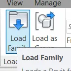
- A dailogue box apperas, from that click on doors, which is the category.
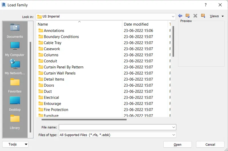
- Another list of doors apperas, below window these are familes.
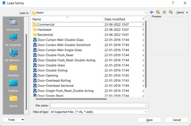
- Click on door single panel.
- Then a dailogue box showing different sizes of doors appears, the different size represent elements.
- 30"x80", 30"x84" , 32"x84", 34"x80".
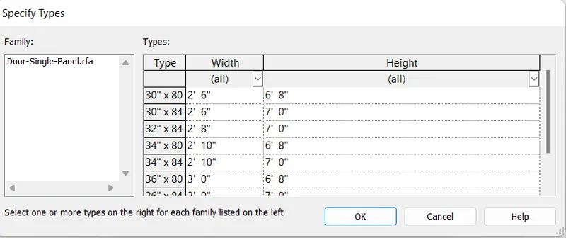
- Select 30"x80" (element) and click ok, then the door gets loaded in the door properties in architural tab.
- Go to architectural tab, select the door(category), go to single flush (family) and select 30"x80"(element) which is loaded.
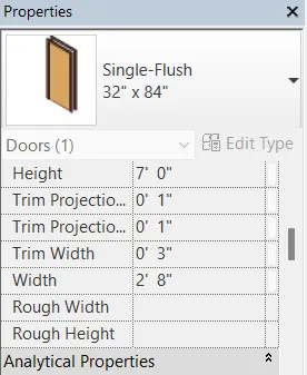
- click on the 30"x80" size door and place it ina wall created, this is the instance.
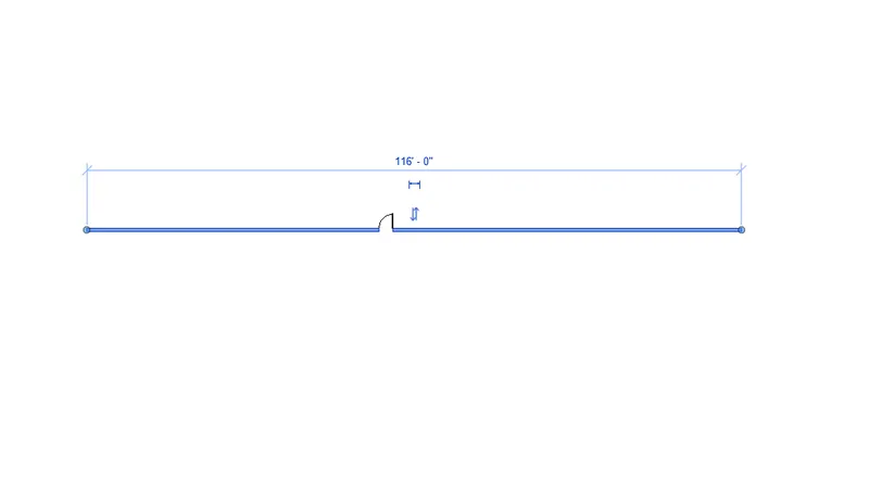
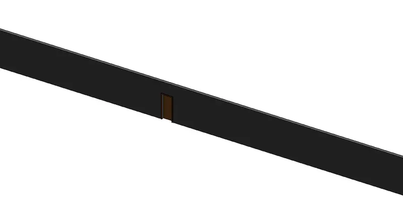
3) Setting up a Project
AIM:
Setting up revit softawre for project.
- Creating template and setting units
-Saving the file
-Adding project information
-creating backups
PROCEDURE:
- Open the project file, select the imperal -aechitectural template.
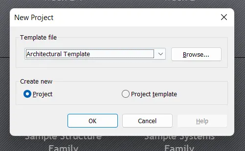
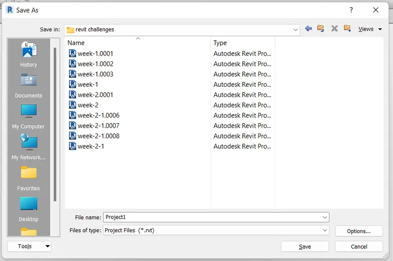
- To save the file : go to the file tab click on svae option and save the name as week-2
- Go to the manage tab, click on project information tab.

- The project information dialogue box appears, enter the organisation name , project details etc.
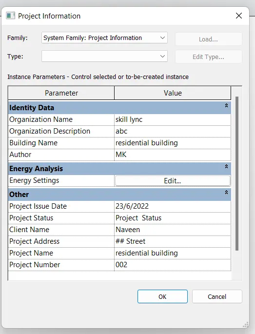
- Setting backups- Go to file menu and click on save as, click on project.
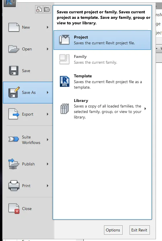
- Click on options in the save as dialogue box .
- File save option dialogue box appears, enter the no of backups as 3.
- Click on ok and then click save.
4) Understand the concept of Levels and Grids. Follow the naming and conventions. Create the following Levels: ( Convert to metric equivalents if metric is your units)
Ground Floor @ 0’
First Floor @ 10’
Second Floor @ 20’
Roof @ 30’
Grids Transverse Grids A, B,C,D, E @ 10’ spacing
Longitudinal Grids from 1 to 10 @ 20’ spacing
ANSWER:
AIM: To create a levels and grids.
Levels:
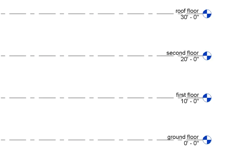
-GF @ 0'
-FF @ 10'
-SF @ 20'
-Roof@ 30'
Grids:
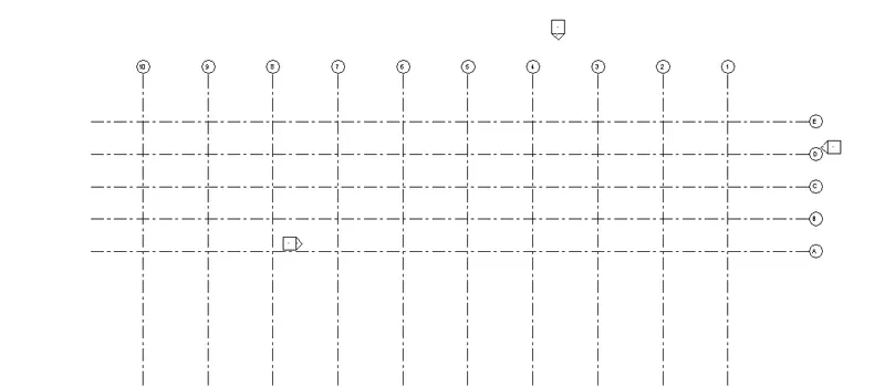
-Transverse grids ABCDE @ 10' spacing.
-Longitudinal grids from 1 to 10@ 20' spacing
Tools:
-Level.
-Grid.
PROCEDURE:
LEVELS:
- Open a new project with the imperal template.
- Go to the elevation-east in project browser
- rename the level 1 as Ground Floor @ 0’
- correspondingly done for the remaining all layers.
GRIDS:
- Longitudinal grigs are drawn from left to the right , 1to 10 and respectively traverse grids are also drawn from A to E both with an equal spacing of 20' .
RESULT:
levels and grids are created.
5) 3D modelling of residential unit
AIM: To draw the layout of 3d modelling of residential unit.
TOOLS USED:
Wall- in architecture tab
Project information- in manage tab
PROCEDURE:
- Go to the metric architectural template, then create a new work space.
- In manage tab go to project information, and add the informations.
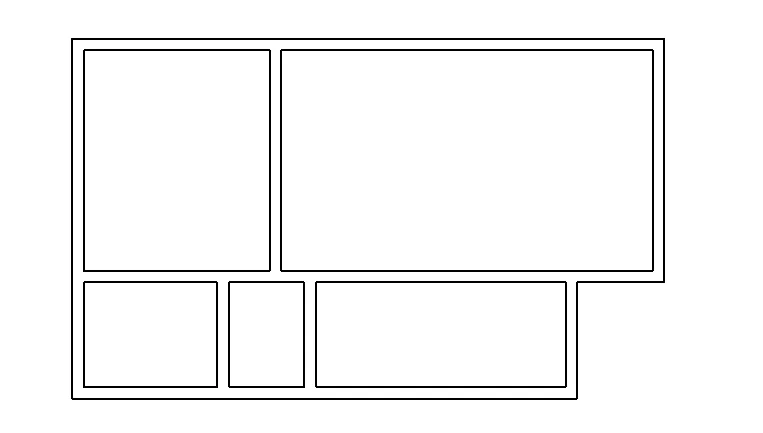
- click on wall in architectural tab, in plan view draw the wall.
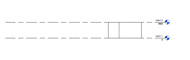
- select height and draw the wall in level1
- change the level 2 to 3000mm if it is not.
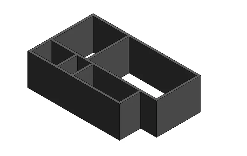
- draw the wall 200mm wall by clicking the workspace.
RESULT:
The layout of 3D residential unit ois created.
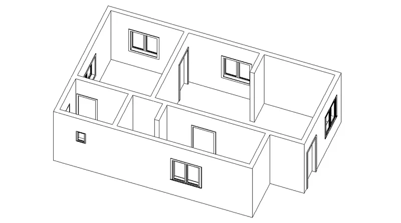
6) In the layout created draft the level of details you are planning to include – Dimensions of room, components you plan to add in the residential unit.
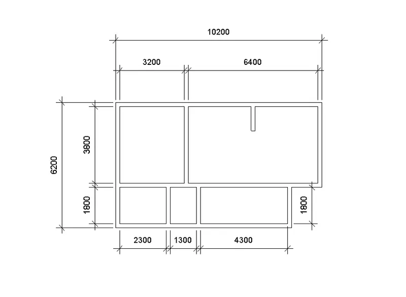
AIM: To created draft the level of details you are planning to include – Dimensions of room, components you plan to add in the residential unit.
TOOLS USED:
DOOR - in architecture tab
ROOm- in architecture tab to add rooms.
WINDOW- in architecture tab
FLOOR- in architecture tab
PROCEDURE:
- In the layout created , dimensions the rooms with annotate tab.
- Click on aglined in the anotate tab and click on the walls where the dimensuions is to be placed.
Placing of Doors:
- Click on the door component from the architecture tab and place it whenever required.
- Select single flush door of 915x2134mm for room doors and 762x 2032mm for toilet door.
Placing of windows:
- Click on the windows component from the architecture tab.
- Place the double casement window in the living room and dinning room 1200x1500mm
- place 850 x 900mm window for all other rooms .
- place a 406x610mm for toilet and store.
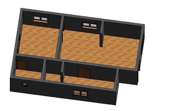
Creating of floors:
- Click on the floor in architectur tab. selet the slab of 150mm thickness
- select the pick points and select the inside of the walls and to draw click on draw line tool.
7) Identify the residential model elements such as Door, Windows, Tables, Chair, Couch, Bed, Lamps from the library and insert them to the model .
AIM: To Identify the residential model elements such as Door, Windows, Tables, Chair, Couch, Bed, Lamps from the library and insert them to the model.
Tools used:
Doors
Windows
Load family- from insert tab
Table
Chair
Sofa
Lamp
Bed
Storage
PROCEDURE:
Placing of Doors:
- Click on the door component from the architecture tab and place it whenever required.
- Select single flush door of 915x2134mm for room doors and 762x 2032mm for toilet door.
Placing of windows:
- Click on the windows component from the architecture tab.
- Place the double casement window in the living room and dinning room 1200x1500mm
- place 850 x 900mm window for all other rooms .
- place a 406x610mm for toilet and store.
Inserting components:
- from the architecture tab, click on the compenents.
- click ona place on a component if not availabe go to insert and click on load families select the table , then click on open.
- slect the table from the properties drop down list.
- select the table we want to place, here table ellipse is selcted for living.