Creating Levels, Grids, Layout and model elements for a residential unit using REVIT
1) What is BIM? Summarize the features of BIM and benefits of using BIM over 2D CAD tools.
BIM :
Building Information Modeling (BIM) is the foundation of digital transformation in the architecture, engineering, and construction (AEC) industry. As the leader in BIM, Autodesk is the industry's partner to realize better ways of working and better outcomes for business and the built world.
Building Information Modeling (BIM) is the holistic process of creating and managing information for a built asset. Based on an intelligent model and enabled by a cloud platform, BIM integrates structured, multi-disciplinary data to produce a digital representation of an asset across its lifecycle, from planning and design to construction and operations.
FEATURES OF BIM :
- Intuitive interface
- Customizable templates
- Multiple board views
- Project scheduling
- Real-time collaboration
- Resource management
- Automations
- Mobile support
- Real-time reporting
BENIFITS OF BIM OVER 2D CAD TOOLS:
What is 2D CAD?
Two-dimensional Computer-Aided Design (CAD) software replaces manual drafting. 2D CAD software allows users to draft designs by representing them as a combination of numerous lines, polylines, and/or geometric shapes. This can be tedious and is difficult to maintain if design changes occur throughout the lifecycle of the project.
What is 3D BIM?
Three-dimensional Building Information Modeling (BIM) provides many advantages over 2D CAD due to the vast capabilities of parametric modeling. All components modeled in 3D BIM software contain real world information about that component. For instance, if you were to place a wall within a BIM model, that wall would automatically include information about it such as its length, width, volume, weight, etc. with little to no additional input from the user. Because of this, once the 3D model is complete the information can quickly and easily be translated into schedules, drawings, and much more.
Models created using 3D BIM software are intelligent, meaning each element placed in the model contains information about the element that can later be reused for other purposes in the project. For example, schedules will be automatically populated as elements are placed in the model. There is no need to manually update schedules since they are a live representation of what exists in the model at that time. Also, once the 3D model is complete, it is a simple task to convert this information into accurate erection drawings, shop tickets, and bills of materials. Another added advantage is that this information can easily be extracted for use in Enterprise Resource Planning (ERP) systems for production scheduling and inventory relief.
Time Savings
3D BIM offers considerable time savings over 2D CAD. In contrast to 2D CAD, change management is largely an automated task with 3D BIM. Because drawings are linked to the 3D model, all dimensional and geometric changes made in the model are automatically corrected on all relevant erection drawings and shop tickets. Also, since all schedules are derived directly from the 3D model, any changes to materials in the 3D model will automatically get populated to the corresponding schedules. This lends to a huge improvement in productivity since users are no longer tasked with the tedious job of manually updating schedules and linework on a multitude of drawings as would be necessary if using 2D CAD software.
Error Reduction
Using 3D BIM software can greatly cut down on potential errors. Naturally it's easier to identify interference between elements and spacial problems in 3D than 2D since you can effortlessly visualize the whole picture which can cut down on costly errors. An additional advantage of 3D BIM is that since all drawings and schedules are updated in real time based on the 3D model, this eliminates the possibility of a drawing or schedule being overlooked and not getting updated with the corrected information which is a real drawback with 2D CAD. With 3D BIM, it's easier to catch and correct errors during the modeling phase rather than making the costly mistake of not discovering them until the production or erection phase.
- Everything in the revit is an element.
- Classes - Elements are modified into a model, datum, or view specific classes.
- sub-classes: Model elements are further classified into host and components and view, specific or further classified into annotations and details items,
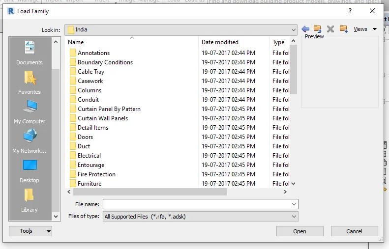
LOADING THE FAMILY FROM REVIT 2021
- Open revit 2021.
- go to the insert tab.
- select the options load families.
- select the particular family and enter in revit.
INSERT TAB:

LOAD FAMILY TAB:
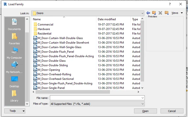
DOOR FAMILY :
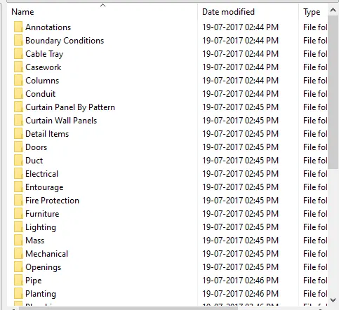
FAMILIES IN REVIT 2021:
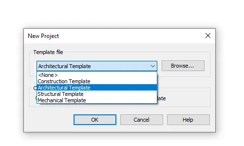
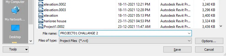
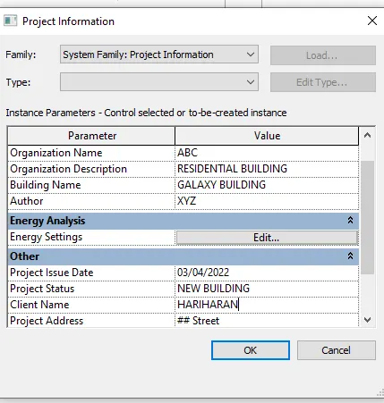
- Go to the file menu.
- select save as option and select save as project.
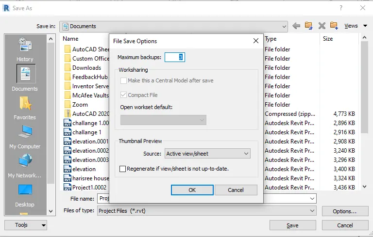
- save as dialogue box will appearing on the screen.
- click on the option tab in the left bottom of the dialogue box and set the maximum backups as 3
4) Understand the concept of Levels and Grids. Follow the naming and conventions. Create the following Levels: ( Convert to metric equivalents if metric is your units)
Ground Floor @ 0’
First Floor @ 10’
Second Floor @ 20’
Roof @ 30’
Grids Transverse Grids A, B,C,D, E @ 10’ spacing
Longitudinal Grids from 1 to 10 @ 20’ spacing
Creating different levels in revit 2021:
- open revit 2021
- open archietectural template
- select project
- a revit screen will be opening
- change the units from mm to feet and inches by commanding un on the screen.
- now creation of different levels go to view tab, on the top bar select elevation.
- from the project browser select to the left to the screen select options select east,
- two basic levels dispalyed on the screen,
- keep the bottom most level and delete the second level.
- rename the bottom level as ground floor and height 0'
- now go to modify command , select the copy
- copy the levels 10',20',30',
- rename levels as ground floor, firstfloor, second floor and roof.
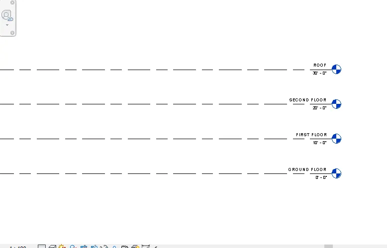
Creating different grids in revit 2021:
- open revit 2021
- open archietectural template
- select project
- a revit screen will be opening
- change the units from mm to feet and inches by commanding un on the screen.
- go to archietectural tab, in that select the grid option,
- draw the grid in the vertical manner which is already named as 1
- copy the grid from modify tab using copy command, @ the interval of 20' facing
- draw the grids intersecting the vertical grids in the same manner and named it as A,B,C,D,E.
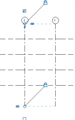
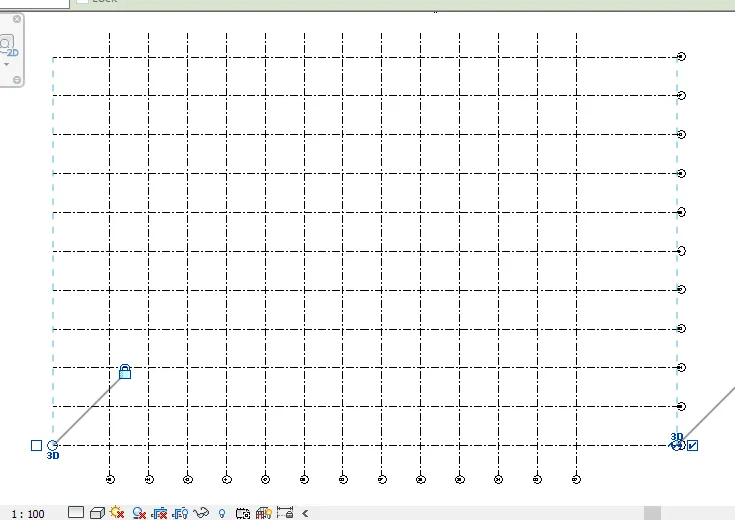
5) 3D modelling of residential unit – From looking at your house / or a place you aspire. Create a conceptual layout of the residential unit. You can measure using a tape or
you can access your residential plan to create a similar layout.
3D modelling of residential unit:
- open revit,with archietectural template,
- enter un , set dimensions into feet and inches,'
- go to wall options in the archietectural tab,
- draw the external walls,
- again go to the wall options, draw the internal walls by changing the wall settings,
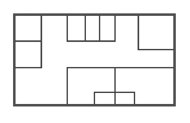
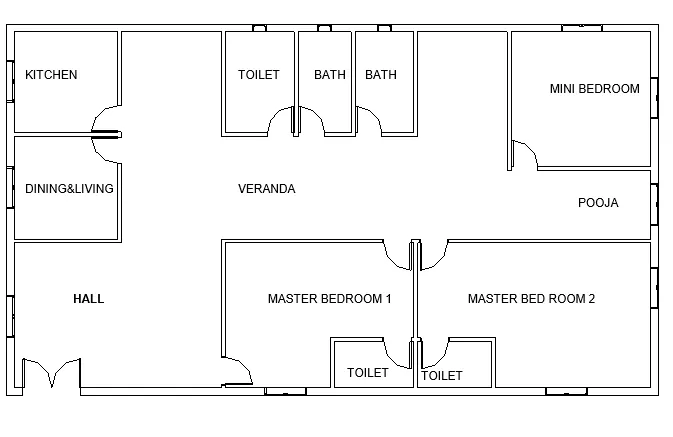
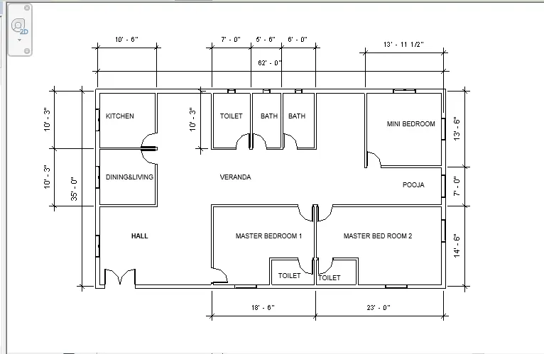
6) In the layout created draft the level of details you are planning to include – Dimensions of room, components you plan to add in the residential unit.
- open revit,with archietectural template,
- enter un , set dimensions into feet and inches,
- go to wall options in the archietectural tab,
- draw the external walls,
- again go to the wall options, draw the internal walls by changing the wall settings,
- CLICK annotate tool bar ,
- select the text to create as shown below,
- click annotate ,
- select the dimensions,
- to clarify the plan in accurate manner,
- click on archietectural tool bar,
- select doors,
- model shown in properties,
- click archietectural tab,
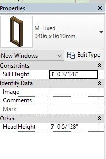
- select windows,
- model shown in propertiers.
- doors , windows , are place as per the desired locations
7) Identify the residential model elements such as Door, Windows, Tables, Chair, Couch, Bed, Lamps from the library and insert them to the model . Save the project for use
for Assignment 3
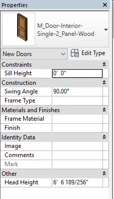
Door model:
- open revit,with archietectural template,
- enter un , set dimensions into feet and inches,
- click on archietectural tool bar,
- select doors,
- model shown in properties,
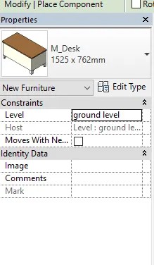
Furniture model:
- open revit,with archietectural template,
- enter un , set dimensions into feet and inches,
- click archietectural tab,
- select components,
- and select place a components
- furniture shown in properties.
Window model :
- open revit,with archietectural template,
- enter un , set dimensions into feet and inches,
- click archietectural tab,
- select windows,
- model shown in propertiers.
RESULTS:
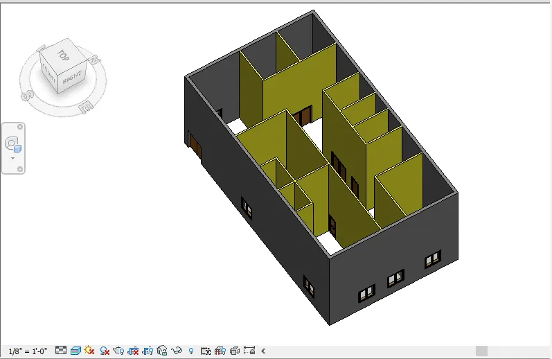
FINAL 3D DRAWING OF RESIDENTIAL UNIT: