Creating Kitchen layout, Hatching of Architectural elements and sectional view of an Industrial Building in AutoCad
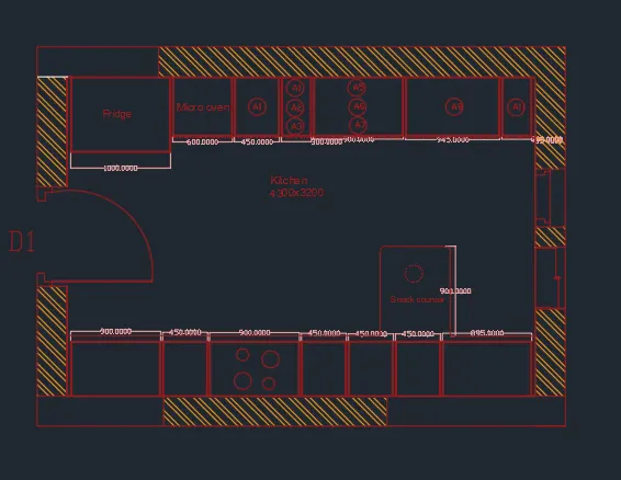
Aim - To create the layout of kitchen and providing hatches to it using autocad in detail
Procedure -
Step 1 - First we have to draw the horizontal line of length 4300mm
- Next draw another line from previouse line with the length of 3200mm vertical
- Next again draw line from previous line with the length of 4300mm horizontal at top
- Next we have to join the first line and last line which we have drawn previously
- Next offset the four sides 20mm outside
- Take offset the inside line of 600mm
- Then draw fridge
- then draw the line in opposite direction to create kitchen parts
- Then draw seven parts of different dimensions compared to upper side
- Leave the space for right and left corner of 35mm
Step 2 - Give the dimensions for every part in the diagram and create the door
- By using single text command and indicate the parts where ever it requires with single text
- And give the dimensions to every part in diagram
- Last draw the snak counter with the length of 600mm and width 900mm,and draw the circle to create hub in middle at bottom of kitchen
- And crate the windows using line command
- And make hatching in drawing
Step 3 - First we have to draw the horizontal line of length 4300mm
- Draw another line from previous line with the length of 3200mm vertically
- Next againg we draw line from previous line with the lenght of 4300mm horizontally at top
- Next we have to join the first line and last line
- Then offset the four side 20mm
Step 4 - to take offset the inside line of 350mm and again take offset of 600mm in same side
- And leave the space for both sides of 35mm
- And take offset for inside part with the length of 10mm for all sides of all part of kitchen
- Take offset of 350mm at bottom portion of kitchen
- Divide the bottom portion into five parts ang again take offset of 10mm
Step 5 - Next we have to use hatch command and make the hatches in wall
- Next we have to draw door using line command,circle command and trim command
- Ans next we have to use dimlinear command to put the dimensions where ever required
- Next use single text command to indicate the kitchen parts in kitchen layout which we have drawn in figure
- Finally we draw the snack counter of 600mm and 900mm
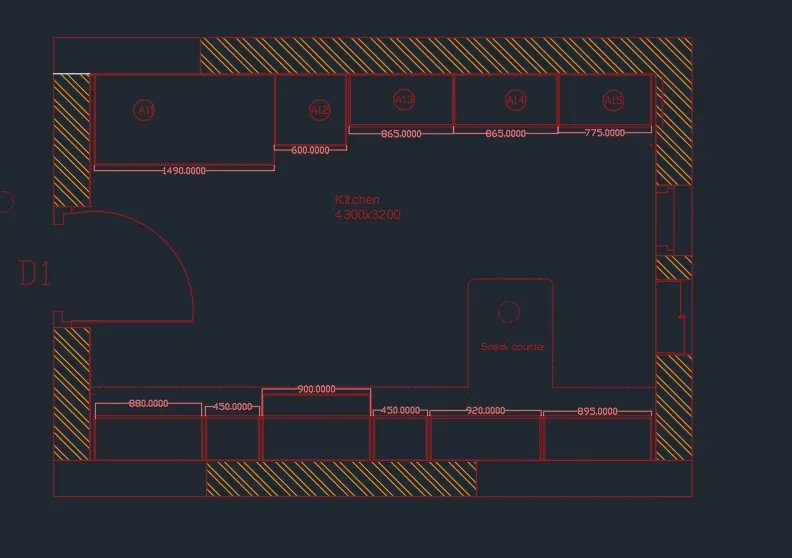
Result - 1) Below counter plan
2) Above counter plan
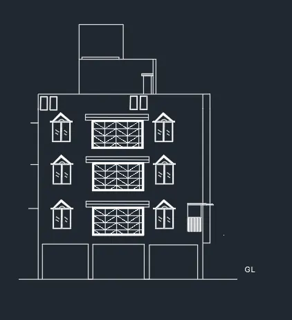
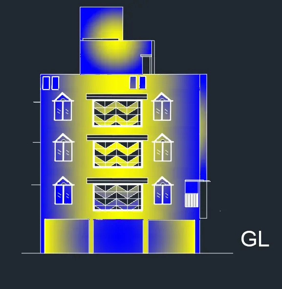
Aim - To create the elevation of plan created in challenge 7
Procedure -
Step 1 - First we have to open the AutoCad and set the limits
- Next use z enter A enter for zoom all
- First we have to draw horizontal line using line command with the length of 11574mm
- Next we need to draw another line from previous line with the length of 12150mm at top
- Next draw the line vertically downward of length 12000mm by drawing the last line and rectangle is formed
- Next draw rectangle at top
- And again draw the another rectangle on the previous rectangle with the length given in drawing
- Then draw three rectangle at bottom of rectangle with different dimensions
Step 2 - Next we need to draw the sunshades provided in drawing
- Next we draw the window with standard dimension with the help of line command and arc
- Next draw thge balcony part using line command,and then offset
- Next we draw remaining architectural elements using line command ,rectangle command and offset command
Step 3 - Finally we use hatch command to hatch the wall,doors,windows and other architectural element as shown in diagram
Result -
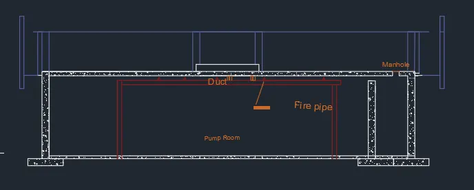
Aim - To create the section of an Industrial building
Procedure -
step 1 - First we have to draw xline at any point on screen
- Next offset the line to top at a distance of 5850mm and we have to do offset to the last line of 300mm to top
- Next we have to draw xline vertical on any point on horizontal line
- take offset of line to right at a distance of 10635mm
- next take the offset of 3900mm to right
- Next take offset to last line at a distance of 5740mm to right side
- Take offset of 5025mm to last offsetted line
- Take offset of 500mm at both edges
- Next we have to trim the outer edges using trim command
- next offset the bottom edge of top floor to a distance of 30mm
- Next offset the last line of 70mm distnace to bottom
- Take offset of 100mm to last offsetted line
- Then draw sprinkler pipe along with duct pipe
- The duct pipe thickness is 300mm and thickness of sprinkler is 100mm
- Next draw the manhole cover with thickness of 750mm at right top edge feed wall as shown in diagram
- Next draw thickness of pump room slab with different layers using line command
Step 2 - Next draw circle of radius 500mm and then enter the text in circle as shown in fig
- Next we need to use single text command to enter the text where ever required in section view of industrial drawing
- Then use hatch command to hatch the wall and floor slab
- Then use dimlinear command to put the dimension whereever required in drawing
result -