Creating Kitchen layout, Hatching of Architectural elements and sectional view of an Industrial Building in AutoCad
1.CREATING KITCHEN LAYOUT, HATCHING OF ARCHITECTURAL ELEMENTS AND SECTIONAL VIEW OF AN INDUSTRIAL BUILDING
Aim:
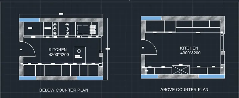
To create the layout of the kitchen and provide appropriate hatch pattern. Also use proper dimension techniques to dimension the plan.
Procedure:
- Initially set the units as Decimal (mm).
- Now, set the limits of the drawing:
- Specify the lower left corner: (0,0)
- Specify the upper right corner: (10000,10000)
-
Below counter plan:
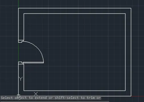
- First type rec in command prompt and create a rectangle of size 4300mm*3200mm.
- Then create an offset of 200mm inwards to create the wall.
- Then, using the line command and circle command create the door for the kitchen.(Width is taken as 800mm)
- Then using line and offfset command create the cabinets for the kitchen.
- Type C to create circle
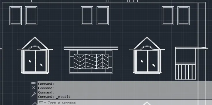
2.To create the elevation of the plan that was already created and to apply proper htch in the walls, doors,windows and other architectural elements.
Procedure:
- Initially set the units as Decimal (mm).
- Now, set the limits of the drawing:
- Specify the lower left corner: (0,0)
- Specify the upper right corner: (15000,15000)
- Using line command initially draw the outline of the structure refering to the challenge 7 plan.
- Provide the necessary hatching as per the requirement.
- Provide the necessaay texts.
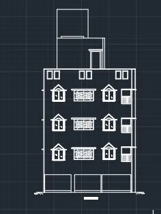
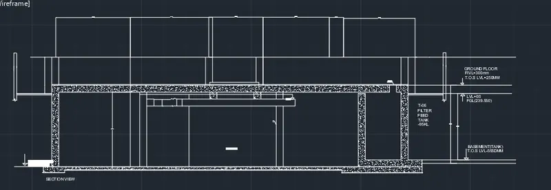
3.To create the section view of an industrial building and provide appropriate hatching and dimensions as required and also provide annotations to the drawing.
Procedure:
- Initially set the units as Decimal (mm).
- Now, set the limits of the drawing:
- Specify the lower left corner: (0,0)
- Use line command to create the outline of industrial building.
- Offset command can be used to offset the lines wherever required.
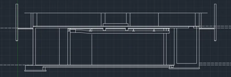
- provide necessary hatching (AR.CONC)in the drawing
- using the command MT provide necessary text and dimensions.