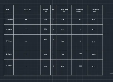
Creating Bar Bending schedule, Different Door types, and Creation of standard drawing templates using AutoCad
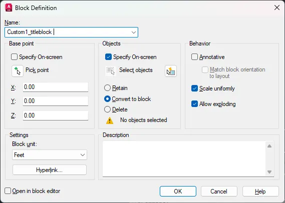
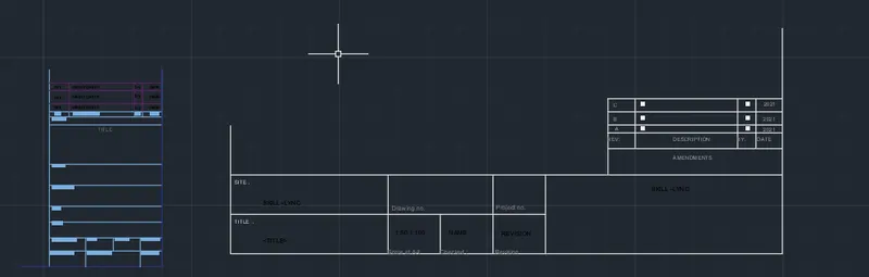
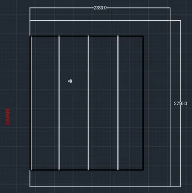
1)AIM- Create the templates as shown in Figures also create a block of this template name as Custom1_titleblock and Custom2_
PROCEDURE :- SELECT the line command , using line command create the template as shown in fig , select single line text from annotate and mention the text as shown , select block command using command window , name the block as Custom1_titleblock and Custom2_ , select pick up point , object and press ok , using insert command block can be bring into the drawing
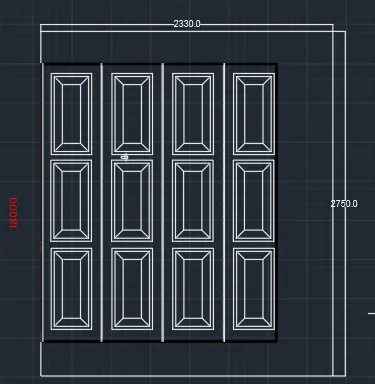
2)AIM-Create the doors type for warehouse as shown in the Figure also create the block of this.
PROCEDURE :- SELECT the line command , using line command create the door as shown in fig , select single line text from annotate and mention the text as shown , select dimension tool , give the dimension where as needed , select block command using command window , name the block , select pick up point , object and press ok , using insert command block can be bring into the drawing
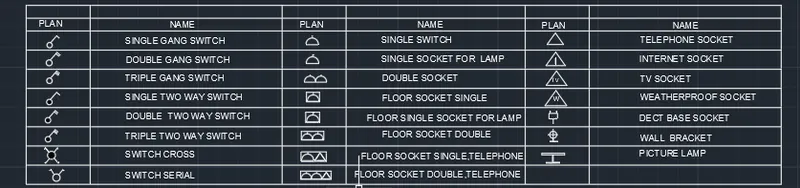
3)AIM-Create each symbol as a block with the name given in the legend. After creating the blocks arrange them in the legend as shown in the Figure.
PROCEDURE :- SELECT the line command , using line command create the TABLE as shown in fig , select single line text from annotate and mention the text as shown , create the legend as shown in table , select block command using command window , create the block of each legend , name the block , select pick up point , object and press ok , using insert command block can be bring into the drawing , place the legend block with the respected name in the table
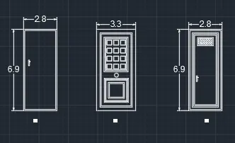
4)AIM-Create the door type for residential building as a block and give the dimensions
PROCEDURE :- SELECT the line command , using line command create the doors as shown in fig , select single line text from annotate and mention the text as shown , select dimension tool and give the dimension , select block command using command window , create the block of each figure , name the block , select pick up point , object and press ok , using insert command block can be bring into the drawing
RESULT
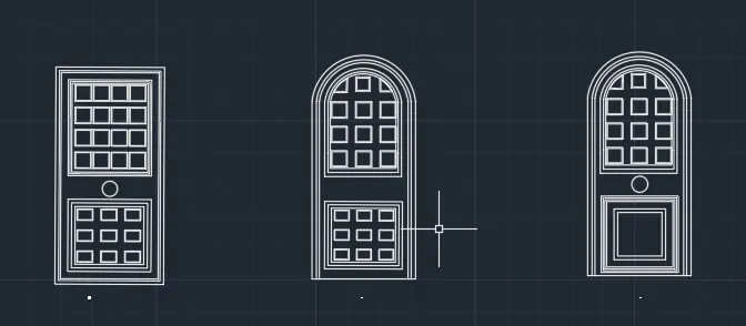
5)AIM-Create each shape as a block as shown in the Figure. and Save the block and insert them on the table
PROCEDURE :- SELECT the line command , using line command create the TABLE as shown in fig , select single line text from annotate and mention the text as shown , create the figure as shown in table , select block command using command window , create the block of each figure , name the block , select pick up point , object and press ok , using insert command block can be bring into the drawing , place the block with the respected name in the table
RESULT