Creating Kitchen layout, Hatching of Architectural elements and sectional view of an Industrial Building in AutoCad
1.
Aim:
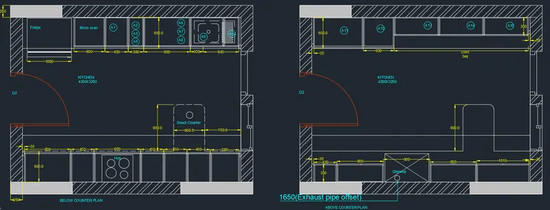
To Create the Kitchen Layout and to Also, use proper dimension techniques to dimension the kitchen layout. Also, insert text wherever required.
Commands Used:
- Line.
- Offset.
- Arc.
- Circle.
- Hatch.
- Dimensions.
- Multiline text.
- Layers.
Procedure:
Step 1:
- Units are set to mm.
- Limits and lim-max are also set .
- Zoom command is also used .
Step 2:
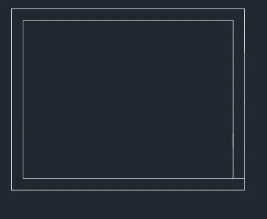
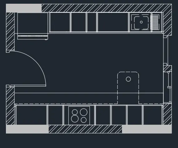
- In the command prompt type rec and the dimensions are 4734 x 3688 mm.
- In the command prompt type offset and offset it to the distance of 250mm.
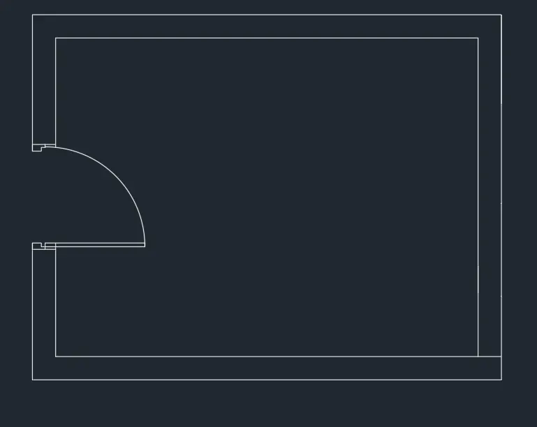
- Using arc and lines the door is drawn .
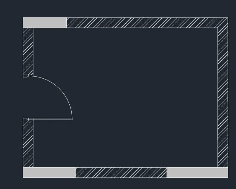
- In the command prompt type hatch to hatch the model .
Step 3:
- In the command prompt type rec > dimensions, to do the fridge .
- In the command prompt type offset and offset it to the desired distance to get the Micro Oven .
- In the command prompt type trim to trim the extras.
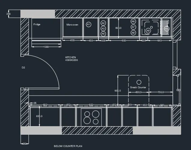
- In the command prompt type offset and offset it to the horizontal distance of 350,450,900,450,450 and 560 .
- In the command prompt type offset and offset it to the vertical distance of 600 .
- In the command prompt type trim to trim the extras .
- In the command prompt type line type and load the dotted lines .
Step 4:
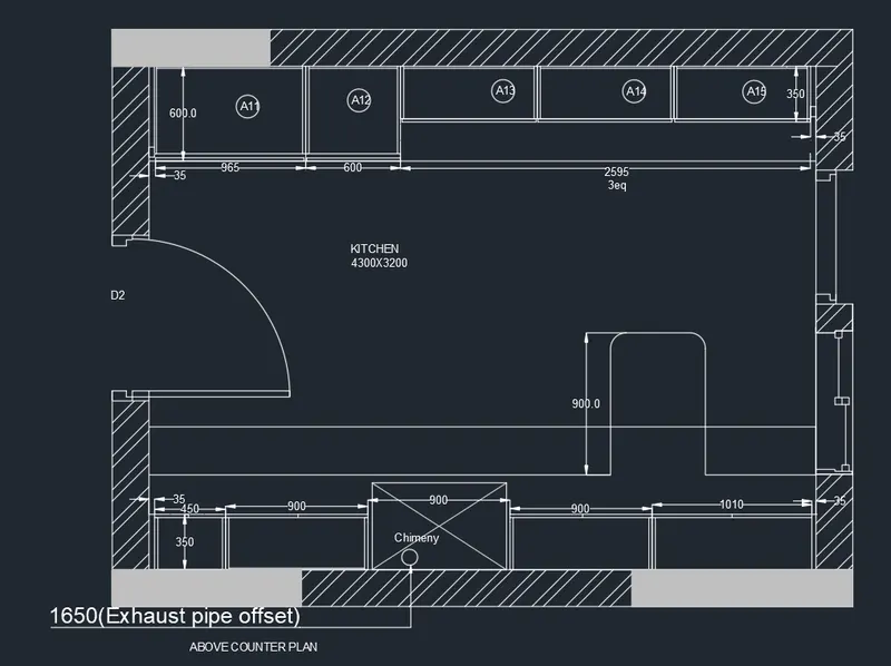
- In the command prompt type text to text the given annotations .
- In the command prompt type dimensions to given the dimensions to your plan .
- In the command prompt even the leader command is used to name the dimensions .
Step 5:
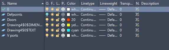
Place all the elements in the required layers .
Result:
2.
Aim: To Create the elevation of the plan and apply proper hatch in the walls, doors,windows, and other architectural elements.
Commands Used:
- Line.
- Rectangle.
- Offset.
- Arc.
- Hatch.
- Dimensions.
- Multiline text.
- Layers.
Procedure:
Step 1:
- Units are set to mm.
- Limits and lim-max are also set .
- Zoom command is also used .
Step 2:
In the command promt enter 'XL' and select Vertical lines.Draw the Projection lines from the given plan.
In the command promt enter 'XL' and select select horizontal lines.Draw the Projection lines from the given section.
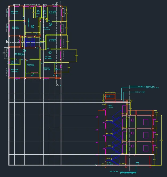
Trim off the unwanted lines .
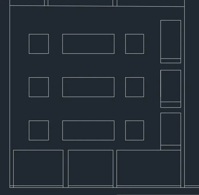
Step 3:
Drawing window:
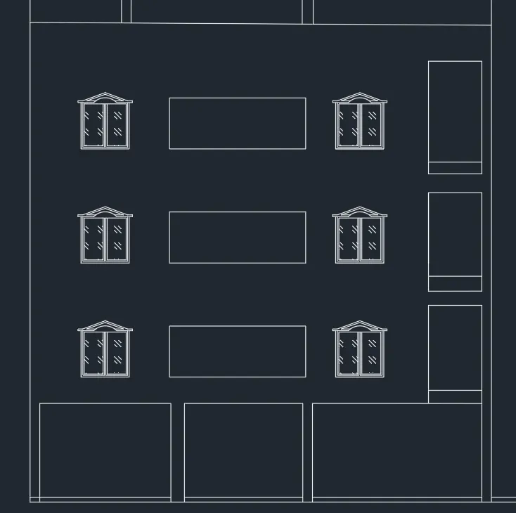
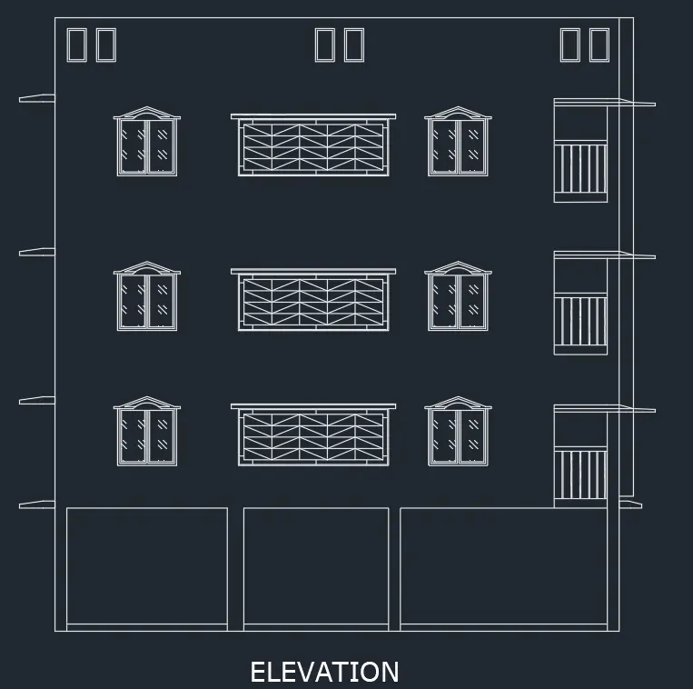
Create a window of 1000mm X 1200mm.Create a rectangle of 1000mm X1100mm and dive the rectangle into two parts .
Offset the centre line with 100mm distance on both sides.Take that as one side of the rectangle draw a rectangle of 900mm X900mm and again offset the retangle 100mm inside .Do the same on the other half.
By using Using Arc crate an arc and by using line create inclined portion @30 degress on the both sides.Hatch the window doors with th Ghost glass hatch and scale it to the required size.
Make that window as block and insert the window in the required places.
Step 4:
Drawing Varandah:
By using join command join all the lines and offset the rectangle of 300mm and divide the rectangle horizontally into 4 parts and vertically into five parts.
Join the the lines to obtain the required pattern.Make it as block and place it in the above two floors.
Drawing of Balcony:
Divide the bottom line of bolcony into six parts and draw the lines and projects the lines @ 600 mm upwards.
Provide the sun shade at the edge of the wall on the both sides.Copy it in the above floors.
Step 5:
Drawing of Over head tank:
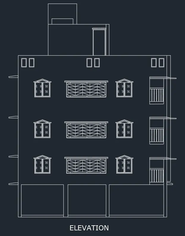
Off set the floor line to the distance of 2500mm ,600mm and 1200mm and project the lines from the plan and columns from bottom and trim the un wanted lines.
Provide a door of 1000mm X 2100mm at the right corner.
Result:
The elevation of the given plan is created:
3.
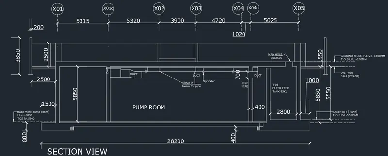
Aim: To Create the section view of an industrial building ,to provide appropriate hatches and dimensions wherever required and also, provide annotations to the drawing.
Commands Used:
- Line.
- Offset.
- Polygon.
- Rectangle.
- Arc.
- Hatch.
- Dimensions.
- Multiline text.
Procedure:
Step 1:
- Units are set to mm.
- Limits and lim-max are also set .
- Zoom command is also used .
Step 2:
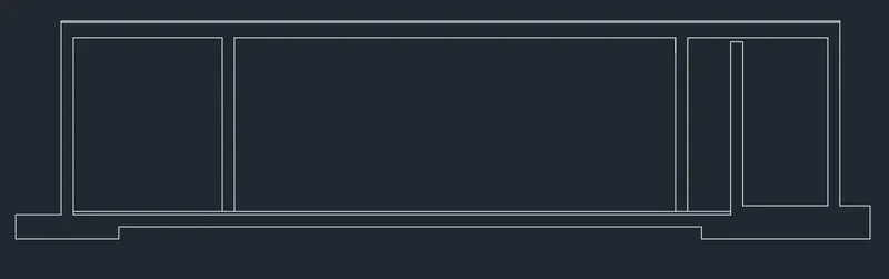
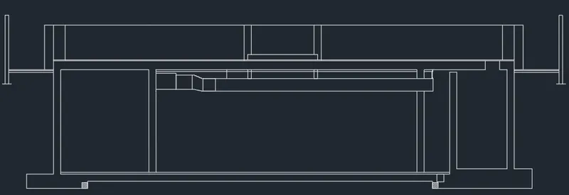
In the command prompt enter line an d draw a line of length 28200mm and offset the line 400mm,top the top two times.By using line command join all the lines and trim off the unwanted lines.
Draw a line of 6400mm vertically up wards from the end of above offset line.Offset the line @1700,5315,5320,3900,4720,1020,5025mm.
Offset the the Above offseted lines by 200mm on the both sides.Connect all the vertical lines by line command horizontally.
Offset the horizontal line @500mm down wards .Trim the all unwanted lines.
Step 3:
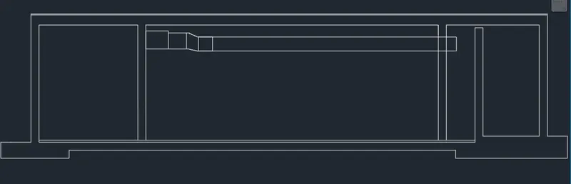
Provide duct of pipe of 15450mm X 700mm Between the middle Two columns.
Draw a rectangle of 1100mm X 900 mm at the second left column and draw another rectangle of 900mm X 800mm.Draw an another rectangle of 700mm X 700mm at a distance of 600mm from second rectangle.
Connect the two triangles by using line command in the steps manner as thread as 90mm and riser as 20mm.
Step 4:
Offset the above line @2500mm vertically up wards and project the corner columns .offset the line @5320mm from the second left column.Again offset the line @400mm,3500mm and 400mm.
Trim of the unwanted lines.offset the line between middle two columns at a distance of 300 mm up wards. Project the middle columns down wards to the duct pipe.
Offset the left column line @500mm,2500mm,2700mm to-wards left side.Extend the line from column to the ofseted line.Offset the extended line @50mm ,100mm to down wards. Trim off the unwanted lines.By using mirror commnad mirror the same in the other side.
Create a man hole of 700 X 500mm at the right corner column.
Step 5:
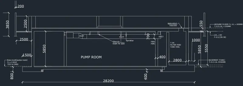
By using dimension style command change text as verdana , text height is 400mm and arrown size as 200mm.Give all the diamnesions.
By using multiline text write the text.
By using the multileader command provide multileaders whereever required and write the text.
Step 6:
Provide concrete hatch in the columns.
Provide the centre to center distance of the columns on the top and text it by drawing a cirlce and use multiline text and insert the text in the circle.
Result:
The section view of industrial building is drawn: