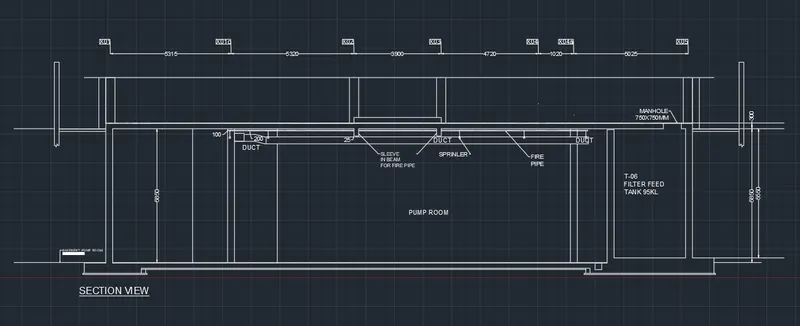
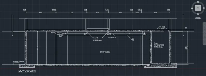
Creating Kitchen layout, Hatching of Architectural elements and sectional view of an Industrial Building in AutoCad
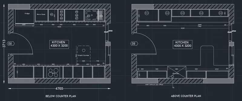
To create kitchen layouts with hatch patterns, blocks, and appropriate dimensions using AutoCAD software, you can follow the procedure outlined below:
-
Launch AutoCAD: Open the AutoCAD software on your computer and create a new drawing file.
-
Set up the drawing units: Ensure that the drawing units are set to the appropriate scale for your kitchen layout. For example, you can set the units to feet or meters, depending on your preference.
-
Start with a floor plan: Begin by drawing the walls of the kitchen using the Line or Rectangle tools. Ensure that the dimensions of the walls match the actual dimensions of the kitchen.
-
Add doors and windows: Use the Rectangle or Polygon tools to draw doors and windows in their respective locations. Consider using standard door sizes, such as 36 inches wide and 80 inches tall, and standard window sizes for accuracy.
-
Insert appliances and fixtures: Utilize blocks or pre-made AutoCAD symbols for appliances like refrigerators, stoves, dishwashers, and sinks. Insert these blocks into the appropriate locations in your kitchen layout, ensuring they are properly scaled.
-
Create cabinets and storage: Design the cabinets and storage spaces by using the Rectangle or Polygon tools to draw their outlines. Convert them into blocks to simplify the design and placement process. Insert the blocks representing the cabinets into their respective locations.
-
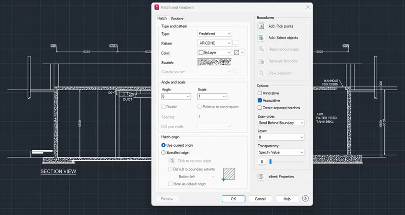
Apply hatch patterns: Use the Hatch command to apply appropriate hatch patterns to represent different surfaces. For example, select a hatch pattern for the kitchen floor, walls, and countertops. Specify the scale and rotation of the hatch patterns as needed.
-
Add dimensions: Use the Dimension tool to add accurate dimensions to your kitchen layout. Measure the lengths of walls, distances between appliances, and countertop lengths. Ensure that all dimensions are clearly visible and labeled.
-
Review and refine: Carefully review your kitchen layout in AutoCAD, checking for any errors or discrepancies. Make any necessary adjustments or refinements to optimize the design. Ensure that the layout is functional, aesthetically pleasing, and adheres to building standards.
-
Save and print: Save your AutoCAD drawing file to your desired location on your computer. You can also print a hard copy of the kitchen layout for reference or sharing purposes.
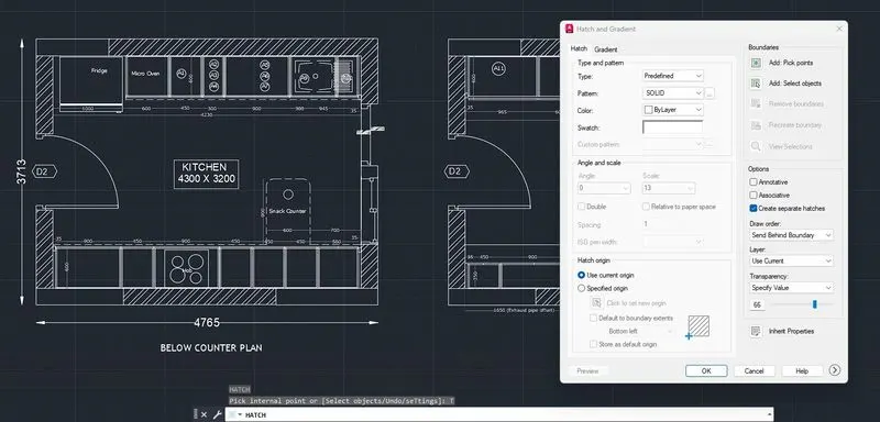
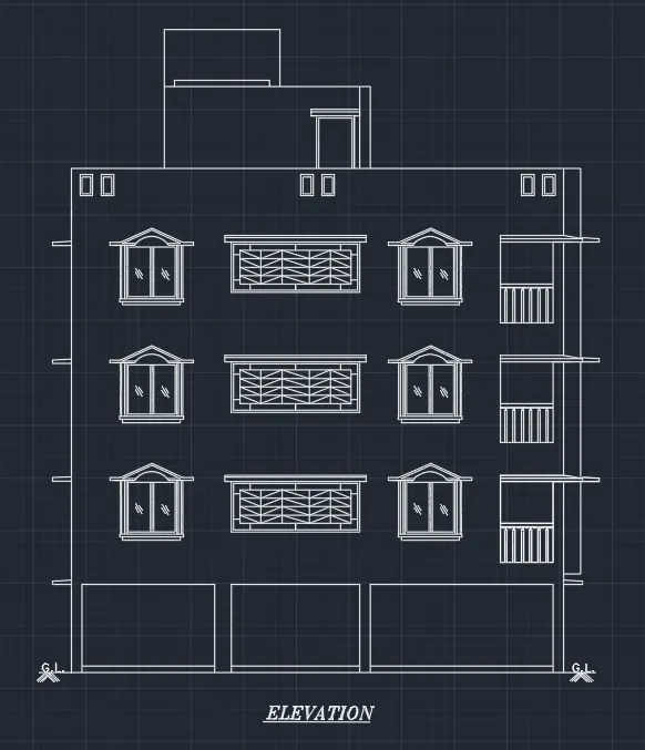
To create an elevation view of the plan created in AutoCAD software and apply proper hatch patterns to walls, doors, windows, and other architectural elements, you can follow the procedure below:
-
Open the AutoCAD software: Launch AutoCAD on your computer and open the drawing file that contains the plan you want to create an elevation view for.
-
Set up the view: Before creating the elevation, set up the appropriate view by adjusting the zoom level and orientation. Use the Zoom and Pan tools to navigate to the desired section or area of the plan that you want to create an elevation for.
-
Create the elevation view: To create an elevation view, you can use the Elevation command or the Viewport tool.
a. Elevation command: Type "ELEV" or "ELEVATION" in the command line and press Enter. Specify the two corner points to define the elevation view rectangle. You can choose to create a single elevation view or multiple views, depending on your needs.
b. Viewport tool: Alternatively, you can use the Viewport tool to create a separate viewport for the elevation view. Activate the Layout tab and create a new layout. Use the Viewport tool to draw a rectangular viewport on the layout, and then adjust its size and position accordingly.
-
Apply hatch patterns:
a. Walls: Use the Hatch command to apply a proper hatch pattern to represent the walls in the elevation view. Select the desired hatch pattern from the available options or create a custom hatch pattern if necessary. Specify the boundaries of the walls to apply the hatch pattern.
b. Doors and windows: Similarly, use the Hatch command to apply appropriate hatch patterns to represent doors and windows. Choose hatch patterns that differentiate them from the surrounding walls. Apply the hatch pattern within the boundaries of the doors and windows.
-
Add additional architectural elements: Depending on the level of detail required, you can add hatch patterns to other architectural elements such as columns, beams, or decorative features. Use the Hatch command and select the appropriate pattern for each element.
-
Customize hatch patterns: If the default hatch patterns do not match your requirements, you can create custom hatch patterns using the BHATCH or HATCHEDIT command. These commands allow you to define your own hatch patterns based on specific requirements.
-
Review and refine: Carefully review the elevation view, ensuring that the hatch patterns accurately represent the different architectural elements. Make any necessary adjustments to the hatch patterns or the elevation view itself to achieve the desired result.
-
Save and export: Save your AutoCAD drawing file, and if necessary, export the elevation view as a separate file format, such as PDF or DWG, for easy sharing and printing.
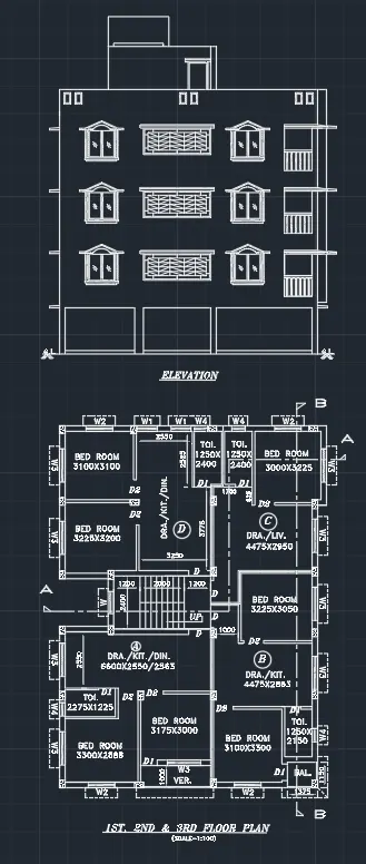
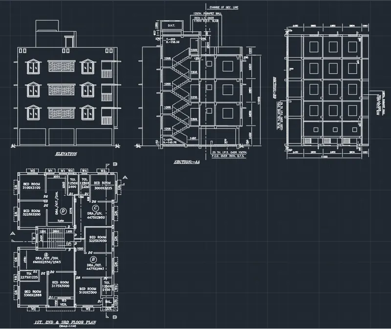
Creating a section view of an industrial building with appropriate hatches, dimensions, and annotations in AutoCAD software can be done by following the procedure outlined below:
-
Import the drawing: Open AutoCAD and import the drawing of the industrial building that you want to create a section view of. Ensure that the drawing is properly scaled and aligned.
-
Set up the section plane: Determine the location and orientation of the section view within the building. Choose a plane that provides the best representation of the building's features and functionality. This could be a vertical or horizontal plane, depending on the specific requirements.
-
Create a cutting plane: Use the Line or Polyline tool to draw a cutting plane line that represents the section line. Ensure that the cutting plane intersects the building at the desired location and orientation.
-
Generate the section view: Activate the Section Plane command in AutoCAD. Select the cutting plane line as the section line. AutoCAD will create a section view based on this line.
-
Apply hatches: Use the Hatch command to apply appropriate hatch patterns to represent different materials and elements within the section view. Select the desired hatch pattern from the available options or create custom hatch patterns if needed. Apply hatches to walls, floors, roofs, and any other relevant elements.
-
Add dimensions: Use the Dimension tool to add accurate dimensions to the section view. Measure the heights, widths, and distances of various elements within the building. Place dimensions where they provide the most clarity and understanding of the building's features.
-
Include annotations: Add text annotations to the drawing to provide additional information and clarifications. Use the Text tool to insert annotations such as labels, callouts, and notes. Position the annotations near the respective elements they describe.
-
Provide labels and legends: Include labels or legends to identify different materials, equipment, or areas within the industrial building. These labels can be inserted as text or as symbols using blocks or external references.
-
Review and refine: Thoroughly review the section view, hatches, dimensions, and annotations to ensure accuracy and clarity. Make any necessary adjustments or refinements to improve the overall presentation of the drawing.
-
Save and export: Save the AutoCAD drawing file and export the section view as a separate file format, such as PDF or DWG, for easy sharing and printing.