Creating Bar Bending schedule, Different Door types, and Creation of standard drawing templates using AutoCad
Aim:
To Sketch the given drawing using Blocks and Attributes using auto cad.
Procedure:
-
Launch AutoCAD: a. Open AutoCAD on your computer.
-
Set Up the Drawing:
-
Create a new drawing file by clicking on the New icon on the toolbar or by typing "NEW" in the command line and pressing Enter.
-
Set the appropriate units for your project by typing "UNITS" in the command line and pressing Enter. Select the desired unit type (e.g., inches, millimeters) and precision according to your project requirements. Click OK to apply the settings.
-
-
Create the Title Block:
-
Use the Line (L), Polyline (PL), Rectangle (REC), or other tools to draw the outline of the title block based on the determined size. Consider leaving sufficient space for the necessary information and elements.
-
Add text using the DTEXT command or Single Line Text to input the required information into the title block. Include details such as project name, sheet number, author, date, and revision information.
-
Use attributes for elements that may require dynamic or editable data, such as revision numbers or drawing scales. To create an attribute, use the ATTDEF command. Specify the prompt, default value, and other properties as needed.
-
Apply appropriate layers to different components of the title block to organize and manage the drawing elements effectively.
-
-
Save the Title Block as a Block:
-
Select all the elements that make up the title block by dragging a selection window around them or by using the Select (S) command.
-
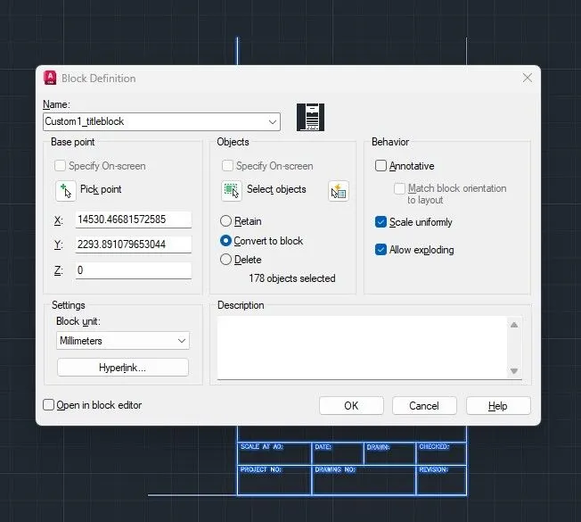
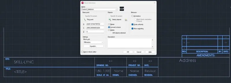
Type "BLOCK" in the command line and press Enter to open the Block Definition dialog box.
-
Specify a name for the block, such as "Custom1_titleblock" or "Custom2_titleblock".
-
Choose the desired insertion point and base point for the block. Ensure that the base point aligns with the bottom-left corner of the title block.
-
Set the appropriate scale factor and rotation angle based on your requirements.
-
Click OK to save the title block as a block with the specified name.
-
-
Draw the Door Types:
-
Start by drawing the first door type based on the provided dimensions or standard size. Use the Line (L), Polyline (PL), or Rectangle (REC) tools to create the outline of the door.
-
Apply layers to distinguish between different components of the door, such as the frame, panels, glass, etc.
-
Add necessary details, such as dimensions, hinges, handles, and locks, using appropriate tools or commands.
-
Repeat the above steps to draw each door type shown in the figure, ensuring you follow the provided dimensions or standard sizes for each door.
-
-
Create Door Type Blocks:
-
Select all the elements that make up the first door type by dragging a selection window around them or by using the Select (S) command.
-
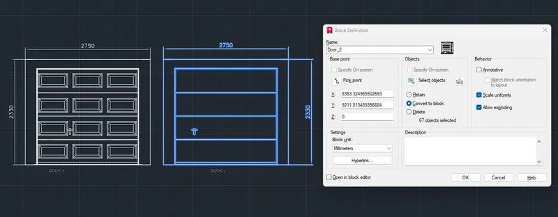
Type "BLOCK" in the command line and press Enter to open the Block Definition dialog box.
-
Specify a name for the block, such as "Door_1".
-
Choose the desired insertion point and base point for the block. The insertion point should be at the bottom of the door, while the base point can be at any convenient location.
-
Set the appropriate scale factor and rotation angle based on your requirements.
-
Click OK to save the door type as a block.
-
-
Repeat the above steps to create blocks for each door type shown in the figure, giving them appropriate names such as "Door_2".
-
Create Symbols as Blocks:
-
Start by creating the first symbol based on the provided image or description. Use the appropriate tools, such as Line (L), Polyline (PL), Rectangle (REC), or Circle (C), to draw the symbol.
-
Select all the elements that make up the symbol by dragging a selection window around them or by using the Select (S) command.
-
Type "BLOCK" in the command line and press Enter to open the Block Definition dialog box.
-
Specify a name for the block according to the legend.
-
Choose the desired insertion point and base point for the block. The insertion point should be at a logical location within the symbol, while the base point can be at any convenient location.
-
Set the appropriate scale factor and rotation angle based on your requirements.
-
Click OK to save the symbol as a block.
-
-
Arrange Symbols in the Legend:
-
Use the appropriate tools, such as Text (TXT), MText (MTXT), or Single Line Text, to create text labels for each symbol in the legend.
-
Position the text labels below each corresponding symbol, following the layout shown in the figure or you can use feilds to insert the name of the block you have given to the symbols respectively.
-
Select the text label and the corresponding symbol block together by using the Shift key or the Select (S) command.
-
Type "BLOCK" in the command line and press Enter to open the Block Definition dialog box.
-
Specify a name for the block representing the legend, such as "Legend".
-
Choose the desired insertion point and base point for the block. The insertion point should be at the top-left corner of the legend, while the base point can be at any convenient location.
-
Set the appropriate scale factor and rotation angle based on your requirements.
-
Click OK to save the legend as a block.
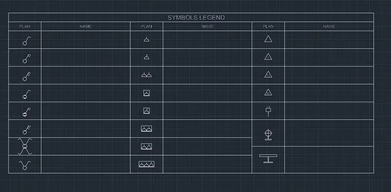
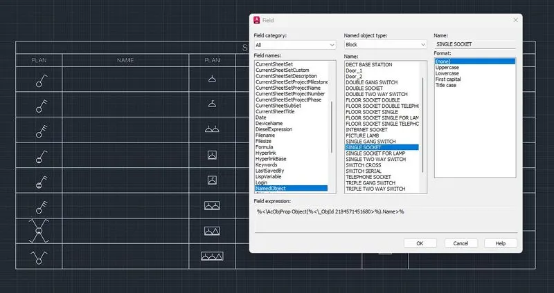
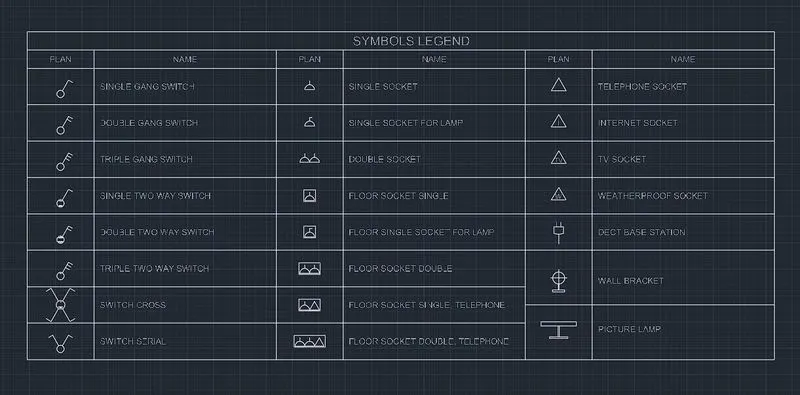
- The same method is also followed for the following detail drawing.
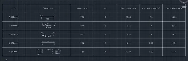
-
-
Draw the Door Types:
-
Start by drawing the first door type based on the provided dimensions or standard size. Use the Line (L), Polyline (PL), or Rectangle (REC) tools to create the outline of the door.
-
Add necessary details, such as dimensions, hinges, handles, and locks, using appropriate tools or commands.
-
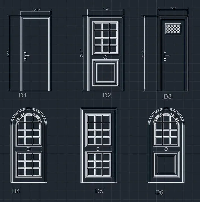
Repeat the above steps to draw each door type shown in the figure, ensuring you follow the provided dimensions or standard sizes for each door.
-
-
Create Door Type Blocks:
-
Select all the elements that make up the first door type by dragging a selection window around them or by using the Select (S) command.
-
Type "BLOCK" in the command line and press Enter to open the Block Definition dialog box.
-
Specify a name for the block, such as "D1".
-
Choose the desired insertion point and base point for the block. The insertion point should be at the bottom of the door, while the base point can be at any convenient location.
-
Set the appropriate scale factor and rotation angle based on your requirements.
-
Click OK to save the door type as a block.
-
-
Repeat the above steps to create blocks for each door type shown in the figure, giving them appropriate names such as "D2,D3,D4,D5 and D6".
-
Save the Drawing: Once you have created and saved the title block as a block, save the drawing file itself by clicking on the Save icon or typing "SAVE" in the command line. Choose a file name and location on your computer to store the drawing.