Creating Kitchen layout, Hatching of Architectural elements and sectional view of an Industrial Building in AutoCad
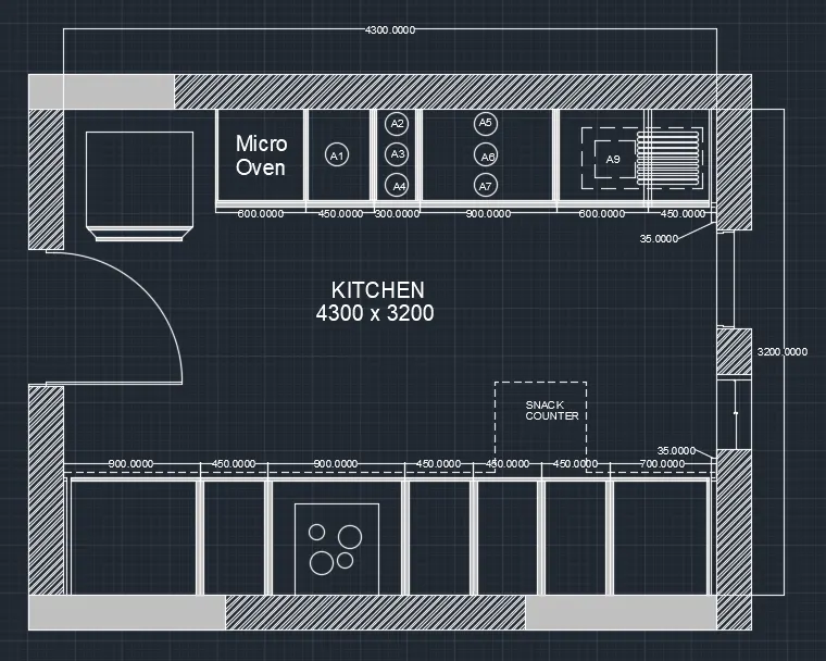
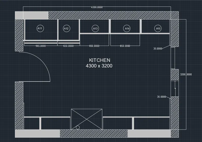
1 . Create the layout of kitchen and provide hatches pattern as shown . Also , use blocks wherever required .
Provide appropriate dimenssion in the plan . assume the size of doors , appliances and other as per the
standards .
Aim : To draw the kitchen layout using the AutoCad software .
Introduction :
varous command used
. QNEW command
. UN command
. REC command
. Offset command
. Explode command
. Circle command
. Line command
. ED command
. MTEXT command
. H command
. block command
. insert command
. ADC command
. DIMLIN command
. DIMCONT command
. Trim command
. Extend command
procedure :
. Above counter plan :
Copy the wall of the below couter plan as the dimenssion are same
i . Sketching Right side counter :
Drawing a line of width 350 mm from the wall , to inside offset 20mm to show the thickness .
offset a distance of 35 mm from te left side of wall .
Now offset 450 mm for the top of the cabinet . offset 900mm for 3 times for the next cabinets .
from the right offset 35 mm , the rest distance of 1095mm will be the cabinet
for the rest of the offset offset 20mm on both sides for thickness
from the plan the below counter and snack counter will be also see sketch that and show it in light colour as same
distance as in the below counter plan
ii . sketching left side counter .
From the left side wall take 35 mm offset to draw the hinge .
Draw 600mm offset as width from the horizontal wall . draw 10 mm offset to show the doors .
Now using offset command draw an offset an 38mm from the 10 mm door for the cabinet
From the 35mm hinge , offset 965 mm to the right A11 . from that offset 600mm for the next cabinet A12.
Take offset of 350mm from the horizontal wall as width of next cabunts .
Offset distance 35 mm from the right . the rest distance is 2665mm which is divided into 3 equals part
Now offset 20mm on both side of division and also 20mm in front for doors
Now offset 10mm in backsides for showing the thickness .
iii . Sketching , Doors , Sliding doors and window :
Create doors in the left wall of the kitchen on both the paln .
Consider doors of 900mm width trim 900mm from the wall thicckness
Draw the hinge of 20mm and draw circle from centre of one hinge to another
Now draw a vertical line from one hinge to circle to show the openning
Now trim thr command and rest trim the rest of the circle
To sketch the window , consider a window of width 900mm
From the 600mm width of cabinet take an offset of 9000mm draw the hinge and shutters of window using ine command
Copy it to te above counter plan . to sketch sliding doors , take 200mm offset from the window . give an openning of
900mm from the 200 mm offset
Below the counter plan .
i. Sketching the wall
Draw a rectangle of 4300 and 3200mm using rectangle tool
Draw an offset of 230mm as well as wall thickness towards outside using offset command
ii . Sketcjing left cabinet and fridge
Fridge is draw on leftmost side by rectangular command take an offset of 1000mm and start drawing slab drawing in
cabinet below
Now using offset command offset 600mm for cabinet below for microwave oven given an offset of 20mm to shown the
partition of cabinet below
For width of cabinet give 600mm offset give 20mm inside offset and 10mm offset for thickness
From 600mm offset of microwave cabinet give an offset of 450mm for A1.
From that give 3000mm offset now from the 300mm offset gove to another offset of 900mm
For all the division of cabinet take 20mm on both side to show the thickness .
to create doors , extend the line of all the division and give 10mm offst on both sides in the 10mm offset given for the
thickness .
iii. Sketching right cabinets and hob .
Using offset command 35mm offset is made from the left and create a hinge .
for width of cabinets give 600mm offset give 20mm inside offset and 10mm offset for thicknesss
from 35mm give 900mm . offset a distance of 450mm three times from the respectively preceding offset.
from the right side 35mm for hinge and rest distance will be 630mm and which shown the top of cabinet . offset a distance will be 630mm which shows the top of cabiet .offset a distance of 20mm on both side pf all offset lines
iv. Sketching snack counter .
Using offset command , pffset a distance of 700mm from the left side of the wall and 900mm from the 600mm width of cabinet . fillet the end of the snack counter with fillet radius 10mm .
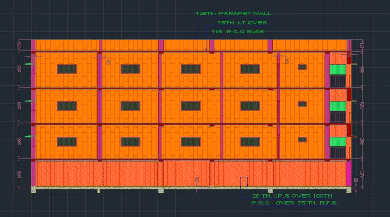
2. Create th elevation of the plan created in the challnege 7 and apply proprer hatch in the walls , doors ,
window , and other architectuaral element . refer to the dimenssion in plans and section in challnege
7 refer to the elevation that needed to be created .
AIM : To create the elevation of plan created in challenge 7 and apply hatches in architrcural element using
Autocad software
Introduction :
various command used
. xl command
. offset commnad
. trim command
. hatch command
. HEdit command
. Arc command
. copy command
. erase command
. rec command
Procedure
step 1 :
- First we have to open the autocad set the limit .
- Next we use the zoom command and press enter .
- Comming to the drawing the elevation of the residential building , first we draw the horozontal line using the line
command with the length of 11574mm .
- next we have to draw the line horizontally with the length of 12000mm by drawing the last line the rectangle will be
formed .
- next we draw the three rectangle at the bottom of the rectangle with the differentiate dimenssion .
Step 2 :
- Next we need to draw the sunshades provides in the drawing .
- next we draw the window with standard construction dimension with the help of line command and arc command
- next draw tye balcony part using the line command , offset command and trim command
- next we need to use the single text command to enter the text downsides the elevation .
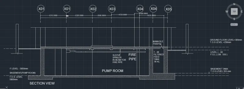
3 : Create the section view of an industrial building as shown in figure . provide appropriate hatches and
dimenssions wherever required . also provide annotation to the drwawing
AIM : to create the section view of an industrial Building by providing hatches and dimenssion in autocad
Introduction :
various command used
. QNEW command
. UN command
. XL command
. line command
. offset command
. hatch command
. line comand
. trim command
. ST command
. MTEXT command
. ED command
. copy command
. Qleader command
. multileader command
. circle command
. DIMLIN command
. DIMCON command
Procedure :
step 1 :-
- First we have to draw the x line at any point on the screen .
- Next offset the line to top a distance of 5850mm and we have to do offset of last offset line to the distance of 300mm
to the top .
- Next we have to draw the vertical X line on any point on the horizontal line .
- Next do offset of line to right to a distance of 10635mm
- Next offset the line with the distance of 3900 to the right .
- Next offset the line with distance of 5740m to the right side .
- next we do the offset for last line with the distnace of 500mm .
- next we have trim the outer edge using the trim command
- next offset the bottom edge of the top floor to a distace of 30 mm.
- next offset the last line with the distance of 100 mm to the bottom
- next we draw the spinkeler pipe along the duct pipe.
- the duct pipe thickness is 300 mm and the thickness of spinkler pipe is 100mm .
- next we draw the manhole cover with te thickness of 750mm at the right top edge of filter feed walls .
- next we draw the thickness of pump room slab with different layers using the line command .
- next we draw need to draw the circle radius of 500mm and enter the next the circle .
- next we need touse the single text command to enter the text where ever required in the section view