Creating Kitchen layout, Hatching of Architectural elements and sectional view of an Industrial Building in AutoCad
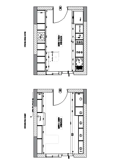
Q-1 Create the layouts of the Kitchen and provide hatches pattern as shown. Also, use blocks wherever required. Provide appropriate dimensions in the plan. Assume the size of doors, appliances and others as per the standards.
AIM AND INTRODUCTION :
Layouts of the Kitchen and hatches pattern as shown in figure is required to be provided using blocks wherever required. Also appropriate dimensions in the plan to be provided assuming the size of doors, appliances and others as per the standards.
PROCEDURE IN DETAIL :
- Layers of various components of kitchen is created
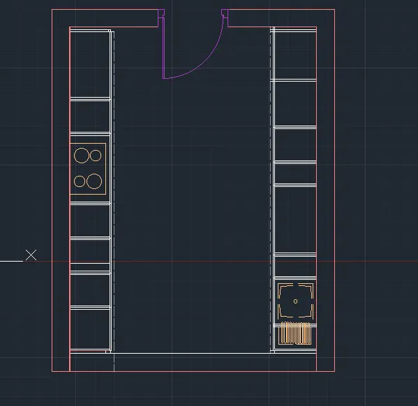
- Using XL command (H/V) , Line and offset command boundary lines and cabinet as shown in the given planof kitchen as per given dimension is created.
- Using Trim and delete command undesired lines are removed
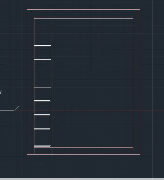
- Usung offset , Trim , Delete , Fillet command partion as per given dimension are created as shown .
- Gas stove is created using line , circle, copy and paste command and converted it as a block using Bolck command and then inserted it at given location using Insert command.
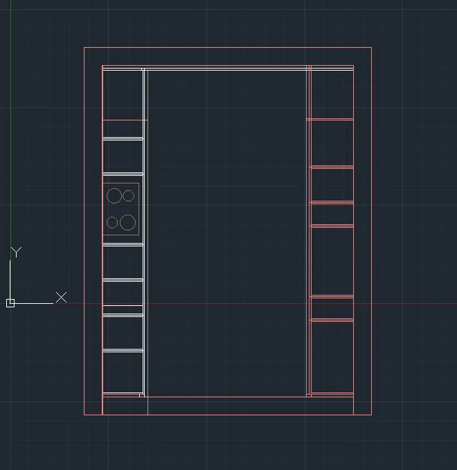
- Using Line , offset , Trim , Erase/ Delete and Arc command Door is created
- Door is made as a block using Block command
- Insert command is used to place the Door as a block at its location
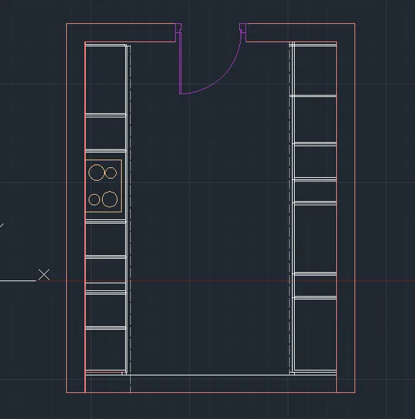
- Using Line , offset , Trim , Erase/ Delete and Circle command Sink is created
- Door is made as a block using Block command
- Insert command is used to place the Door as a block at its location
- Other partion are also created using Line, Offset , Trim, and delete command. Extend command is also used wherever necessary for extending lines to join it to other line.
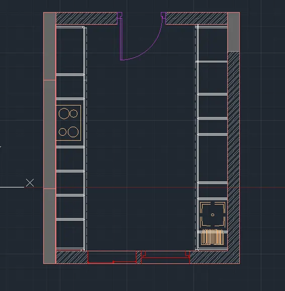
- Hatch command is used to hatch the walls showing the Brick work
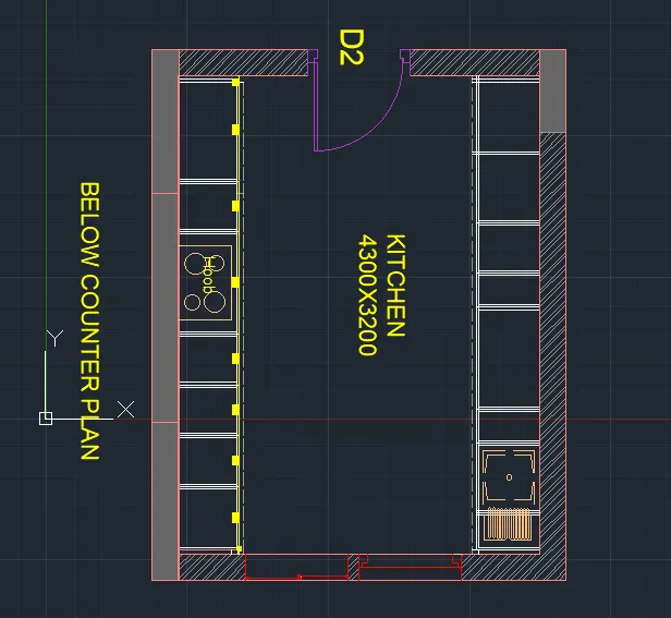
- MT command is used for creating the Text and for its proper size its height is adjusted form properties.
- Dima and Dimc are used for dimensioning and from its property size of dimension, arrow size and its pattern are edited.
Complete plan of Kitchen above counter
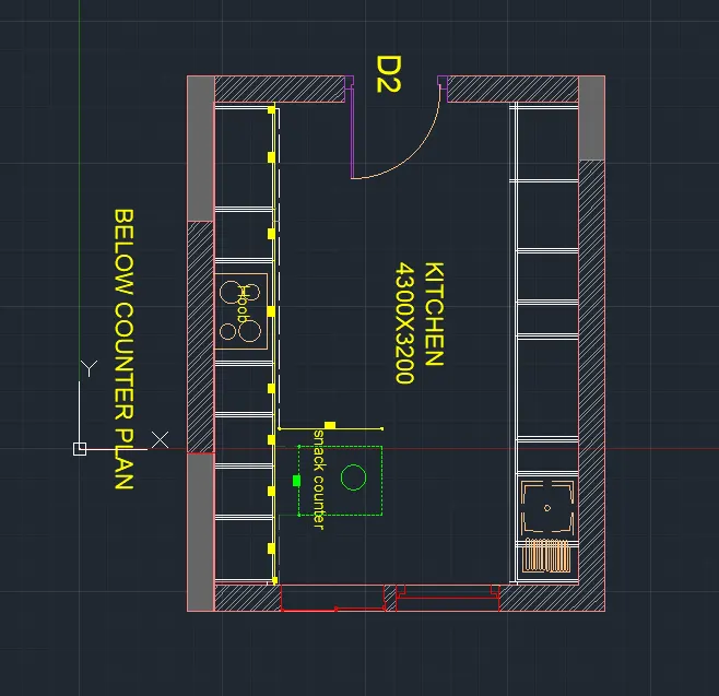
- Above counter plan is created using copy and paste command with below counter plan already created and deleting undesired components from it and creating desired component using the various commands as used earlier.
- Chimeny is created using circle and line command
- Text for chemeny is created using copy and paste command with already created text and then editing it as desired.
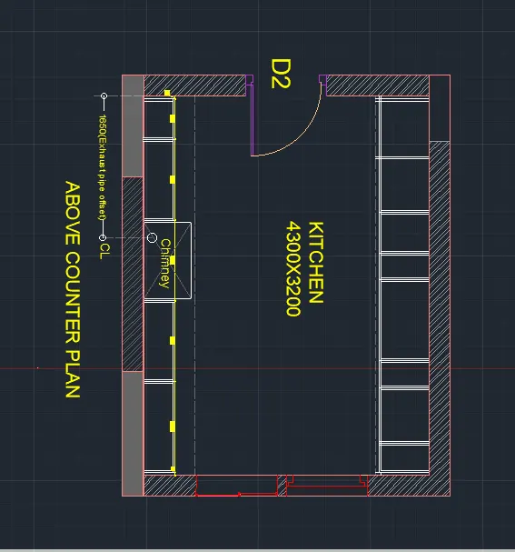
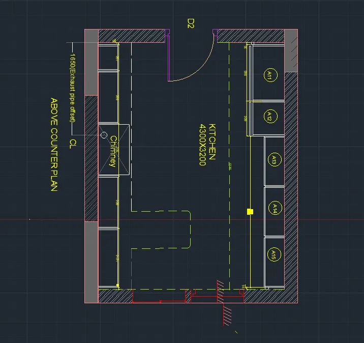
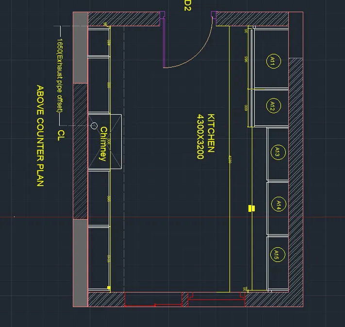
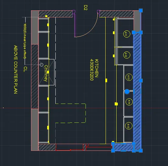
RESULT: 1) Layouts of the Kitchen with hatches pattern as shown in figure and blocks as per requirement is provided
2) Appropriate dimensions in the plan assuming the size of doors, appliances and others as per the standardshas also been done.
3) DWG file of above lay out is attached, snap shots of step wise development of lay out of the kitchen are als attached above
-------------------------xxxxxxxxxxxxxxxx------------END OF Q-1----------xxxxxxxxxxxxxxxxxxxxxxxx--------------------------------------
Q-2. Create the elevation of the plan created in the Challenges 7 and apply proper hatch in the walls, doors, windows, and other architectural elements. Refer to the dimensions in Plans and sections in Challenges 7.
Refer to the elevation that needed to be created.
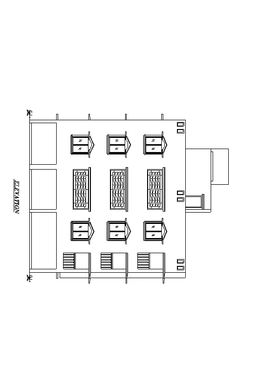
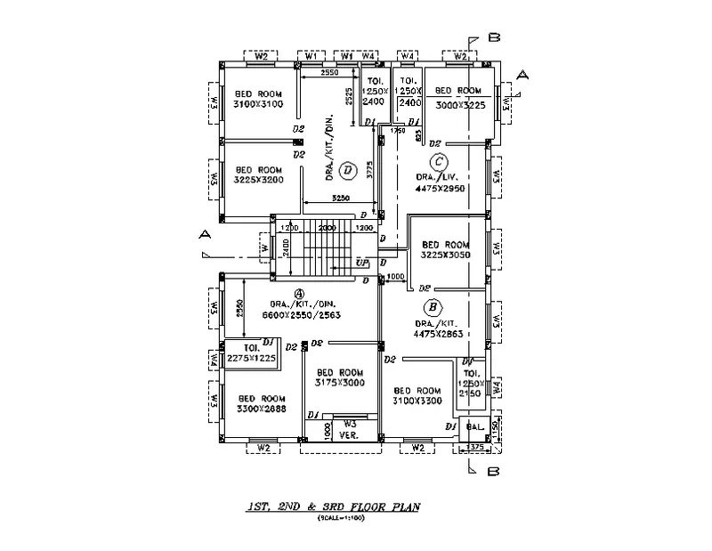
AIM AND INTRODUCTION : Elevation of the plan of Challenges 7 is to be created and proper hatch in the walls, doors, windows, and other architectural elements is to be applied refering to the dimensions in Plans and sections in Challenges 7.
Input : Plan and section of challenge-7 and elevation that need to be created.
PROCEDURE IN DETAIL :
- Usin XL command with its option H/V outer boundary of elevation is created
- Using offset command width and height of the windows and ventilators are marked ( Dimensions /size of windows, ventilator etc are considered from Challenge-7 as directed in this challenge.)
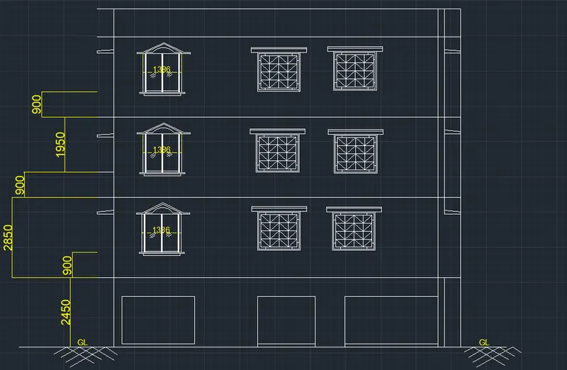
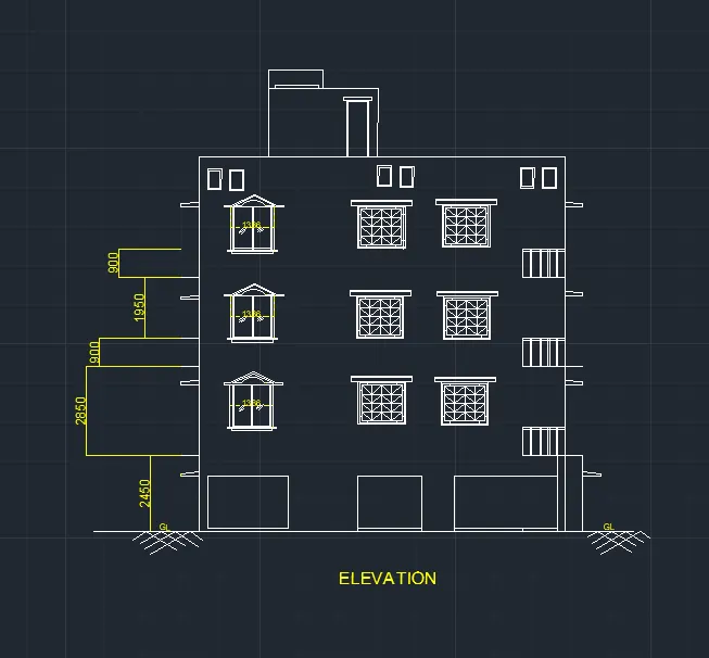
RESULT : Thus elevation of challenge-7 is created including proper hatching of windows , ventilators and other archetectural members as shown above. DWG file is also attached .
-----------------------------------xxxxxxxxxxxx------------------ END OF Q-2 --------------------xxxxxxxxxxxxxxxxxxxxxxx-----------------------------
Q-3. Create the section view of an industrial building as shown in Figure. Provide appropriate hatches and dimensions wherever required. Also, provide annotations to the drawing.
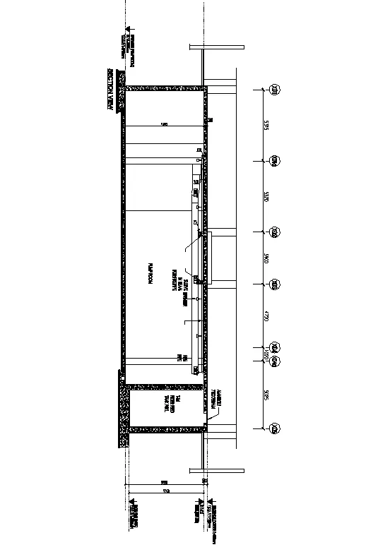
AIM AND INTRODUCTION : Section view of an industrial building as shown in Figure is required to be created and appropriate hatches and dimensions wherever required need to be provided along with annotations to the drawing.
Given : Figure of Industrial Building as shown above.
PROCEDURE IN DETAIL :
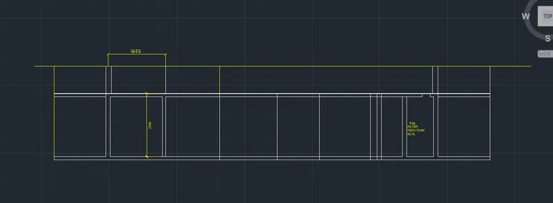
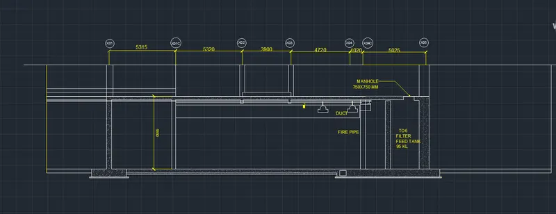
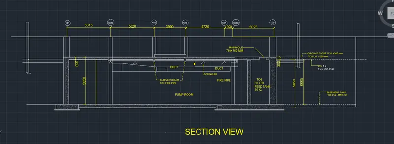
RESULT : Thus Section view of an industrial building as shown in Figure is created with appropriate hatches and dimensions wherever required. Annotations to the drawing is also provided.
-----------------------------------xxxxxxxxxxxxxxxxxxx------------------xxxxxxxxxxxxxxxx END OF Q-3 ---------------xxxxxxxxxxx------------------