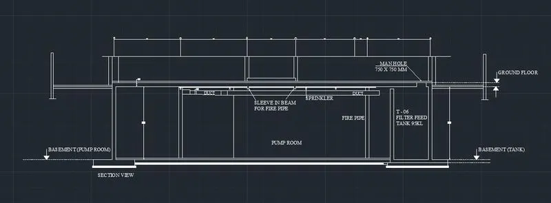
Creating Kitchen layout, Hatching of Architectural elements and sectional view of an Industrial Building in AutoCad
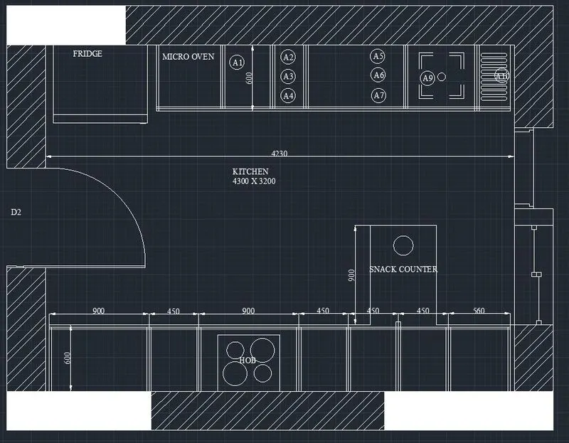
AIM: To create the kitchen layout and to also,use proper dimension techniques to dimension the kitchen layout.also insert text wherever required.
all dimensions are in mm.
procedure:
step1:
- units are set to mm
- limits and limax are also set
- zoom comand is also used.
steps for drawing below counter plan
- open autocad and enter un in command box and make the type as decimal.
- select line command and draw a line of 4300 in x direction and a line of 3200 in y direction
- offset 230 towards all sides of the rectangle outside the figure.
- fillet all the offset edges.
- then continue the same tools for further drawing to complete it.
- after completing it hatch it accordingly and give text to following names.

2.
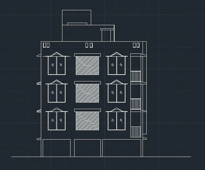
AIM: TO CREATE ELEVATION AND HATCHING THE STRUCTURAL AND NON-STRUCTURAL ELEMNTS OF THE BUILDING LIKE WALLS,COLOUMS ETC
PROCEDURE:
STEPS FOR DRAWING SECTION
- SELCT LINE COMMNAD AND EXTEND THE LINES FROM THE PLAN IN THE DOWNWARD MANNER TO CRREATE PROJECTIONS
- OFFSET THE GIVEN VALUES
- HATCH THE MEMBERS
- NAME THEM BY MTEXT.
Q3.
AIM: TO CREATE THE SECTION VIEW OF AN INDUSTRIAL BUILDING
PROCEDURE:
- IN THE COMMAND PROMPT TYPE I TO DRAW THE LINES
- IN THE RIBBON BAR> HATCH >AR.CONC
- IN THE COMMNAD PROMPT TYPE REC TO DRAW THE REC
- IN THE COMMAND PROMPT TYPE LT TO THE DOTTED LINE.
- TYPE MT TO DRAFT TEXT
- TYPE C TO DRAW CIRCLE
- TYPE TO DRAFT THE DIMENSIONS
RESULT: