Creating Kitchen layout, Hatching of Architectural elements and sectional view of an Industrial Building in AutoCad
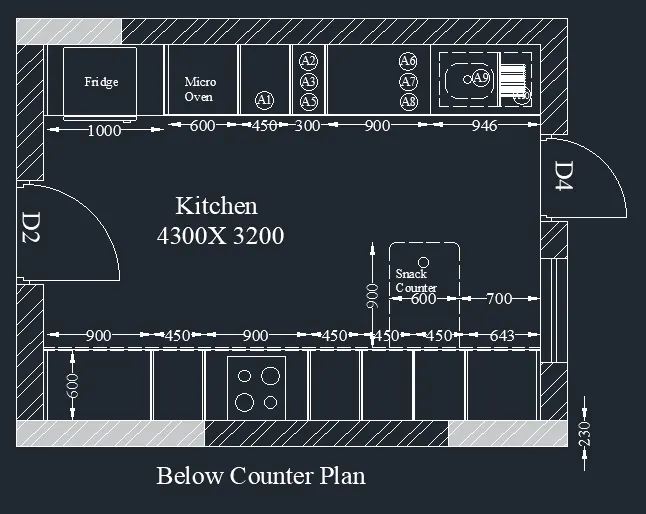
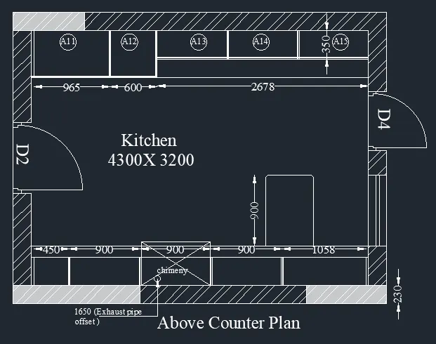
Create the layouts of the Kitchen and provide hatches pattern as shown. Also, use blocks wherever required. Provide appropriate dimensions in the plan. Assume the size of doors, appliances and others as per the standards.
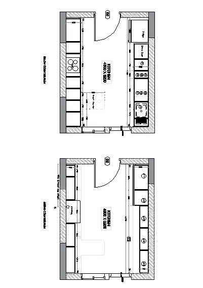
Aim : Create the layouts of the Kitchen and provide hatches pattern as shown.
Procedure :
- Creat the autocad File and give the units for the file decimal , percision 0.00, and said ok .
- And Give the Lmits , Give the Rectangle of 4734 x 3688 mm
- offset 230mm for the wall thickness
- And give the Door and Window from the Ribbon - Veiw - Tool paletts and give the angle for the Door .
- And Give the Hatch to the walls ,offset it to the horizontal distance of 350,450,900,450,450 and 560
- offset it to the vertical distance of 600 and Trim the Remaining Lines it
- And Give the Text for Below Kitchen And Above Kitchen Counter .
- And Give the Dimension using the Dimlinear and Dimcontinous .
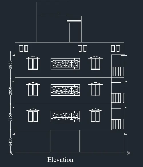
2. Create the elevation of the plan created in the Challenges 7 and apply proper hatch in the walls, doors, windows, and other architectural elements. Refer to the dimensions in Plans and sections in Challenges 7.
Refer to the elevation that needed to be created.
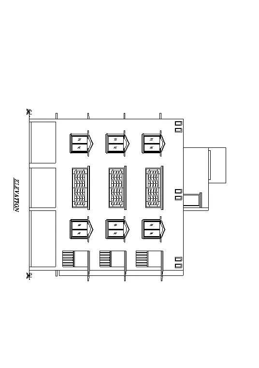
Procedure :
-
Creat the Construction lines of Horizontally and Vertically
-
Give the offset 150mm
-
Give the offset of Ground Floor 2450 , First & Second & Thrid Floor 2850
-
the parapet Wall 1000 and give the doors and windows as per the elevation
- And Give the Windows Elevation and Balcony and Ven And Show the reamaning elevation details in it using the line command and also trim the unwanted lines in it .
- And Give the text using the text command.
- And Also dimension using the Dimlinear and dimcotinous .
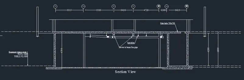
3. Create the section view of an industrial building as shown in Figure. Provide appropriate hatches and dimensions wherever required. Also, provide annotations to the drawing.
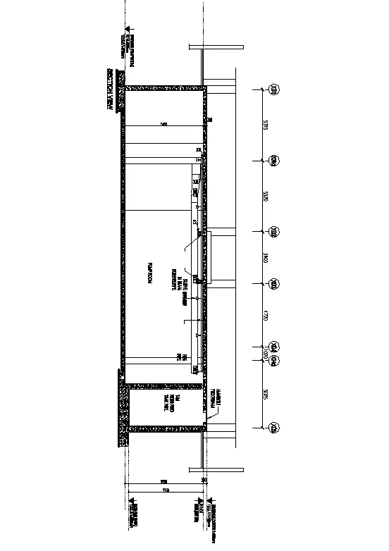
Procedure :
- First we have to draw the X-line
- offset the line to top to a distance of 5850mm and again offset of last offset line to the distance of 300mm to the top ,the vertical X-line on any point on the horizontal line.
- offset of line to right to a distance of 10635 ,offset the last line with a distance of 3900mm to the right.
- offset the lst line with the distance of 5740mm to the right side.
- the offset for last line with the distance of 5025 to the right side.
- Offset the left and right edges with the distance of 500mm. trim the outer edges using the trim command.
- offset the bottom edge of the top floor to a distance of 30mm.
- offset the last line with a distance of 70mm to the bottom.
- offset the last line with the distance of 100mm to the bottom.
- draw the splinkler pipe along with the duct pipe.
- The duct pipe thickness is 300mm and the thickness of splinkler pipe is 100mm.
- the manhole cover with the thickness of 750mm at the right top edge of filter feed walls as shown in the figure.
- the thickness of pump room slab with the different layers using the line command.