Creating Kitchen layout, Hatching of Architectural elements and sectional view of an Industrial Building in AutoCad
AIM: To create kitchen layout, hatching of architectural elements and sectional view of an industrial building in AutoCad
Introduction :
- Open autocad application
- Type Qnew and open new drawing
- Set units according to drawing
- Switch on object snap and object snap modes : Endpoint, Midpoint, Center, Nearest, Intersection, Perpendicular and Node
- Ortho mode is ON
Problem 1
AIM : To create kitchen layout and providing hatches using AutoCad
PROCEDURE :
- Set units to decimal
- Procedure for dimensions setting : Enter command dimstyle
Click on new and create a new style "STYLE 1"
1. Now go to Lines section and set the following:
Color, linetype and lineweight remians "ByBlock"
Suppress extension lines
2. Next go to symbols and arrow section and set the following:
Arrow size 20
3. Next go to Text and set the following:
Text style : Standard : Font style - Arial, Font name regular
Text color : Byblock
Text height : 100
Text placement both vertical and horizontal as centered, View direction as left to right
Offset from dimline : 1
Text aligment : Aligned with dimension
4. Next go to Fit and set the following:
Use overall scale of 1
5. Next go to Primary units and set the following:
Unit format : Decimal
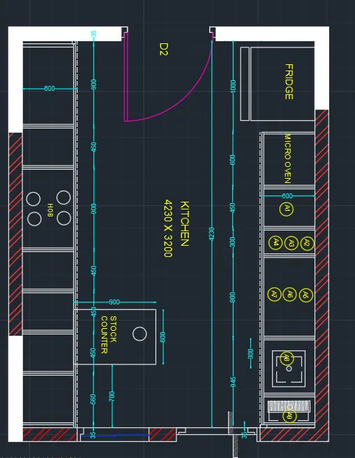
Precision : 0 - Draw a rectangle of size 4530 x 3500mm and draw another rectangle by taking offset distance of 150mm
- Explode both the rectangles
- Trim off top side for rectangle to create an opening of 1040mm
- Now draw a door of size 950 mm
- Draw a two vertical lines at a distance 600mm (dotted line) taken from left and right side
- Draw offset lines to previous line with offset distance of 20mm on both the sides
- Draw horizontal lines using offset at distances 35,900,450,900,450,450,450,560,35 and beside each of these lines draw two more horizontal lines on either sides with offset distances 20mm
- Similarly draw horizontal lines using offset at distances 1000,600,450,300,900,620,945,35 and beside each of these lines draw two more horizontal lines on either sides with offset distances 20mm
- Draw fridge at top right corner
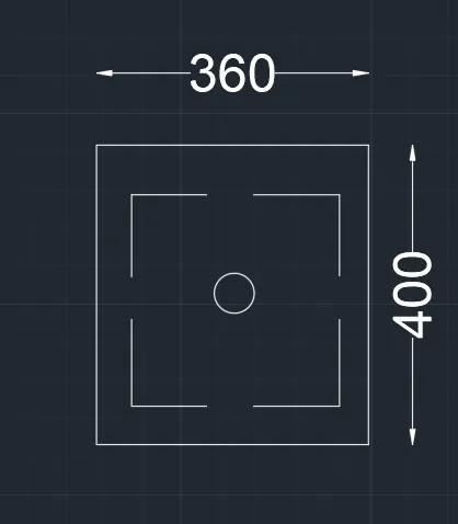
- Create a sink as shown below and save it as block and place it at right bottom corner
- Create a window at the bottom with an opening of 785mm
- Write texts as per given diagram with fontstyle as arial and font height varying from 50-80
- Create kitchen hob and stock counter (size 900x 600mm) as shown below
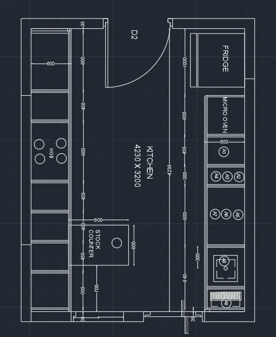
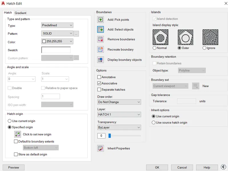
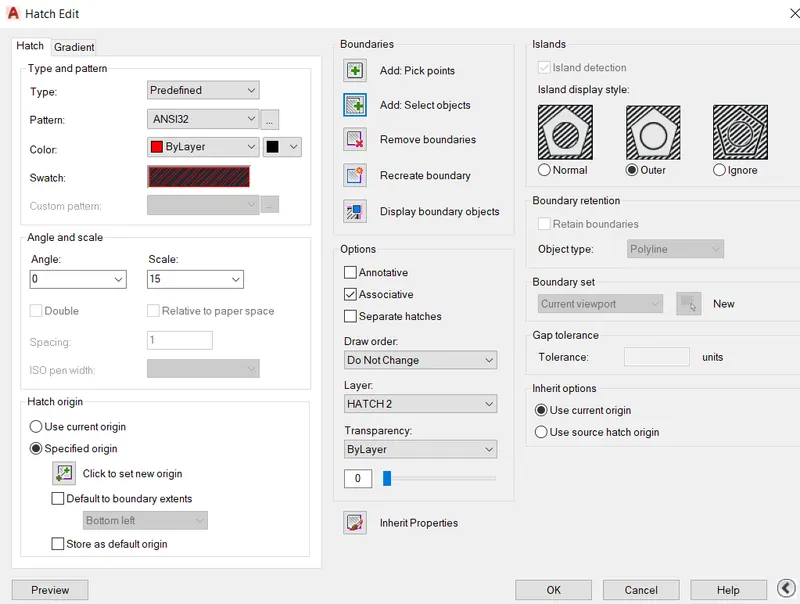
- Hatch the areas as per given diagram using hatch tool and assign it to HATCH1 and HATCH2 layers. Solid hatch pattern and ANSI32 is used.
- Now draw a rectangle of size 4530 x 3500mm and draw another rectangle by taking offset distance of 150mm
- Explode both the rectangles
- Trim off top side for rectangle to create an opening of 1040mm
- Now draw a door of size 950 mm
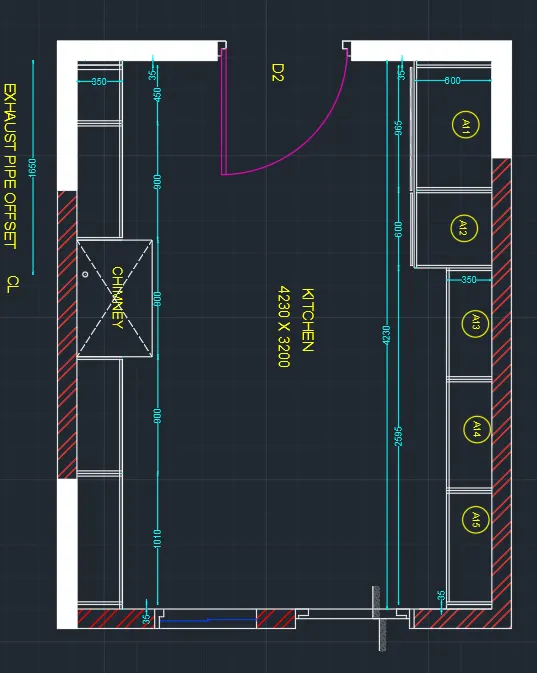
- Draw a three vertical lines at a distance 350mm taken from left and 350mm,600mm taken from right side
- Draw offset lines to previous line with offset distance of 20mm on both the sides
- Draw horizontal lines using offset at distances 35,450,900,900,900,1010,35 and beside each of these lines draw two more horizontal lines on either sides with offset distances 20mm
- Similarly draw horizontal lines using offset at distances 35,965,600,858,858,35 and beside each of these lines draw two more horizontal lines on either sides with offset distances 20mm
- Draw chimney of size 580 x 900mm as per given diagram
- Draw exhaust pipe hole at a distance 1650mm taek from top
- Create a window at the bottom with an opening of 785mm
- Write texts as per given diagram with fontstyle as arial and font height varying from 50-80
- Hatch the areas as per given diagram using hatch tool and assign it to HATCH1 and HATCH2 layers. Solid hatch pattern and ANSI32 is used.
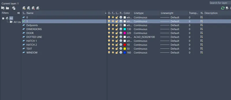
- Different layers are created and assigned accordingly
RESULTS :
Kitchen layouts are created and walls are hatched using different patterns
PROBLEM 2:
AIM : To create elevation plan and hatching elements such as doors, windows, walls and other architectural elements using AutoCad
PROCEDURE :
- Set units to decimal
- Procedure for dimensions setting : Enter command dimstyle
Click on new and create a new style "STYLE 1"
1. Now go to Lines section and set the following:
Color, linetype and lineweight remians "ByBlock"
Suppress extension lines
2. Next go to symbols and arrow section and set the following:
Arrow size 20
3. Next go to Text and set the following:
Text style : Standard : Font style - Arial, Font name regular
Text color : Byblock
Text height : 100
Text placement both vertical and horizontal as centered, View direction as left to right
Offset from dimline : 1
Text aligment : Aligned with dimension
4. Next go to Fit and set the following:
Use overall scale of 1
5. Next go to Primary units and set the following:
Unit format : Decimal
Precision : 0 - Draw a rectangle of size 11750 x 11000mm and explode it
- Draw a line at a distance 150 mm from bottom
- Draw three columns at the bottom of size 250 x 2306 and 300 x 2306 with distances in between 2600mm,3000mm,4600mm
- Draw horizontal lines at distances 2450mm(1st floor), 5300mm(2nd floor) ,8150mm(3rdfloor)
- From first floor at a distance 990mm draw a window 1
- For drawing a window 1 first draw a rectangle of size 1200 x 1100mm
- Draw horizontal lines in the rectangle at a distances 50mm,150mm, 206mm, 1000mm, 1050mm measured from bottom
- Draw vertical lines in the rectangle at a distances 50mm, 140mm, 560mm, 608mm, 658mm, 1104mm, 1150mm measured from left
- Above this rectangle draw another rectangle of size 1800 x 100 mm and draw a semi circle of radius 350 mm by taking midpoint of the rectangle
- Above this rectangle draw a triangle of base 1200mm and height 420 mm placed at the midpoint of rectangle
- Take offset of 50mm in the triangle as shown below
- Trim off the extra lines
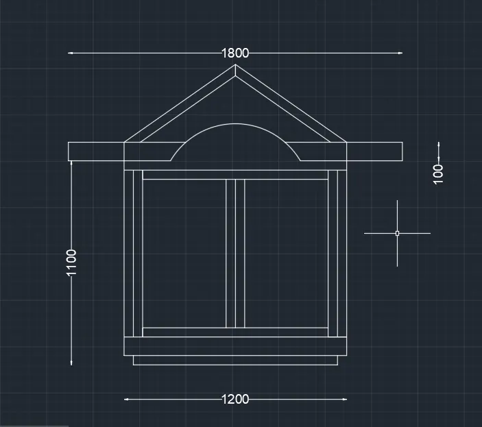
- Hatch the window using four different hatch patterns
- HATCH 1 : ANSI34 (COLOUR 249)
- HATCH 2 : SOLID ( CYLINDRICAL, COLOUR 253 & COLOUR 254)
- HATCH 3 : SOLID (INVERTED HEMISPHERICAL, COLOUR 24)
- HATCH 4 : GOST_WOOD (COLOUR 10, ANGLE 45, SCALE 10)
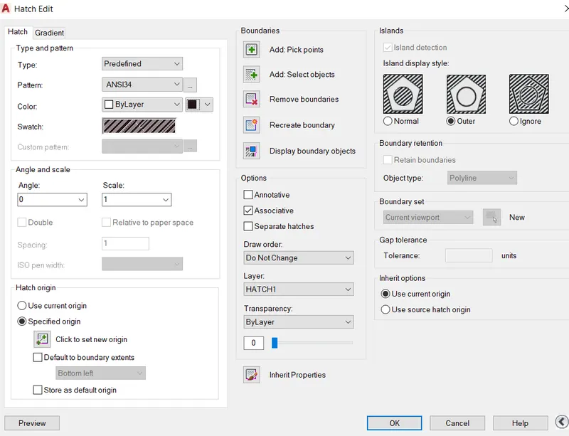
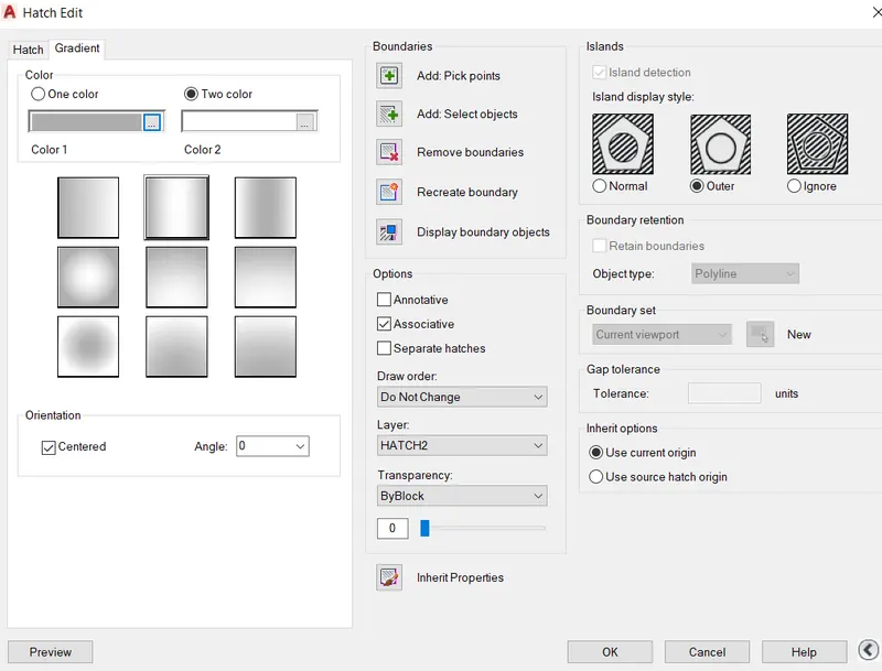
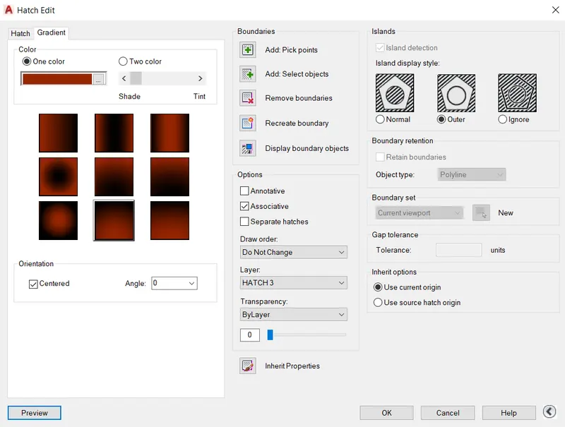
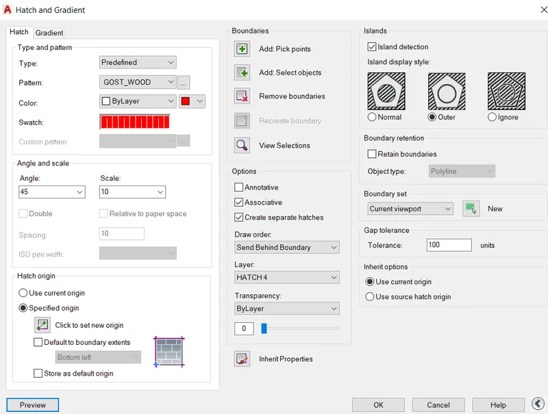
- Hatch the window as shown below
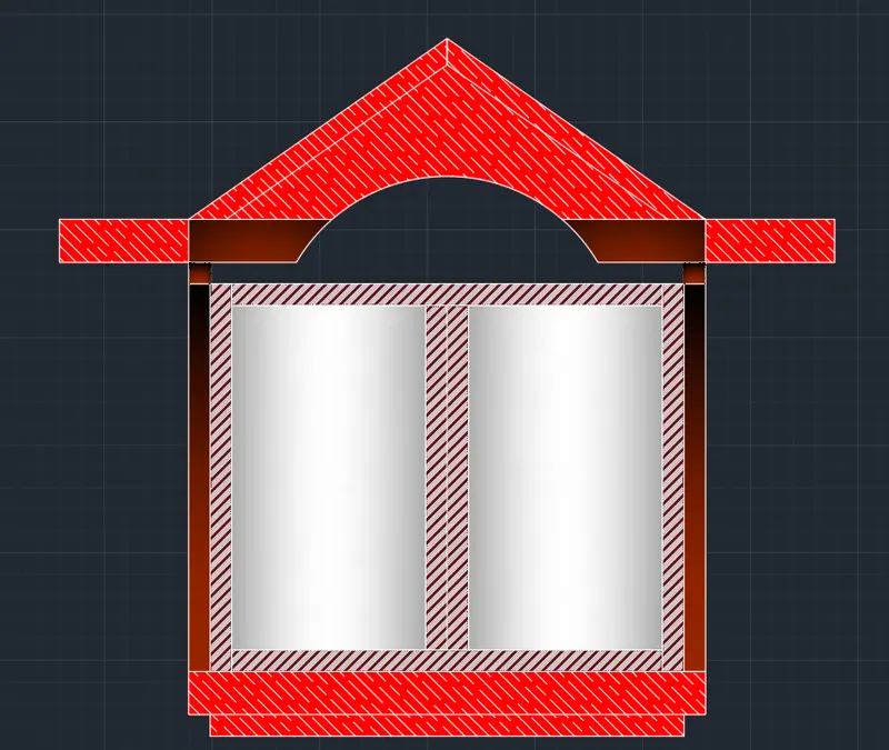
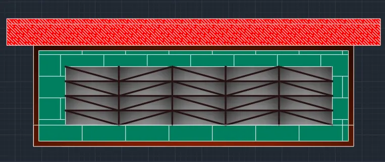
- For drawing window 2: Draw a rectangle of size 3000 x 950mm at a distance 1240mm from first floor
- Take offset of 50mm and 150mm and draw two more rectangales inside
- Draw another rectangle of size 3500 x 250mm above the previous rectangle
- Draw a line at a distance 50mm inside the rectangle
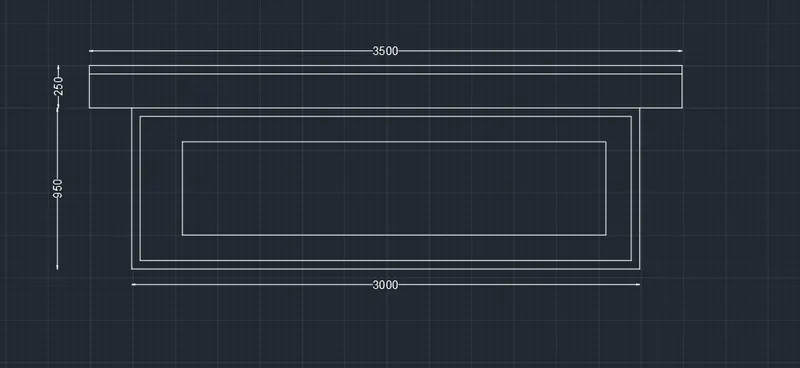
- Divide inner rectangle into 4 columns and draw diagonals with line weight 0.40mm
- Hatch the window using following hatch patterns
- HATCH 3 : SOLID (COLOUR 24)
- HATCH 4 : GOST_WOOD (COLOUR 10, ANGLE 45, SCALE 10)
- HATCH 5 : AR-B816 (SCALE 1 COLOUR 124)
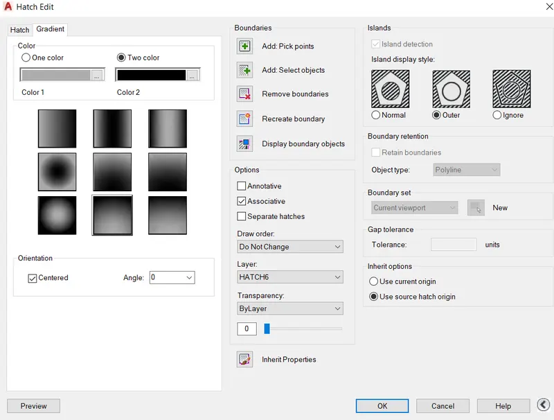
- HATCH 6 : SOLID GRADIET (INVERTED HEMISPHERICAL, COLOUR 253)
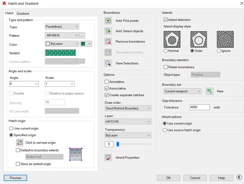
- At each floor draw semi visible balcony with sunshades
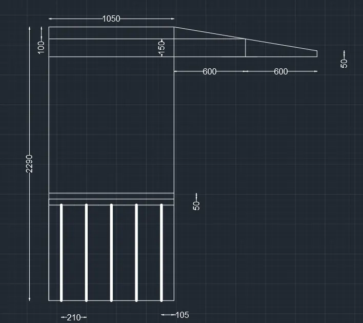
- A rectangle of size 1050 x 2290mm
- Take offset of 100mm and 150mm draw two lines at top of rectangle
- Draw a projection of length 600mm and continue it to draw sunshade of length 600mm
- Draw railings as shown below (0.50mm)
-
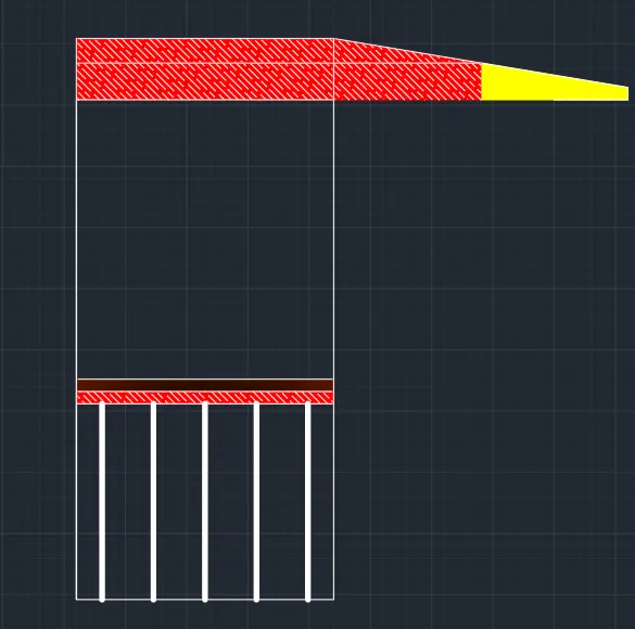
- Hatch the sunshade using solid pattern and colour yellow
- Hatch remaining area using HATCH 3 : SOLID (INVERTED HEMISPHERICAL, COLOUR 24) and HATCH 4 : GOST_WOOD (COLOUR 10, ANGLE 45, SCALE 10) as shown below
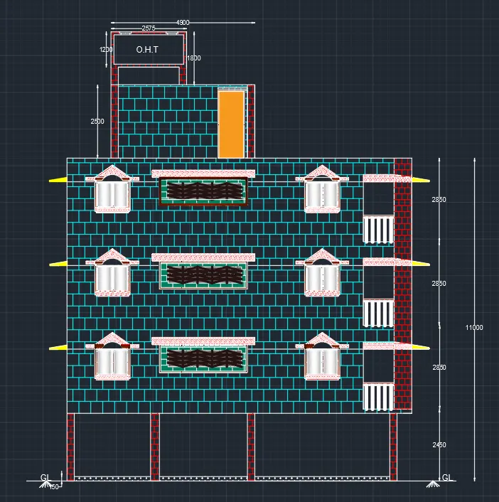
- Refer the figure shown below for the placement of windows and balcony
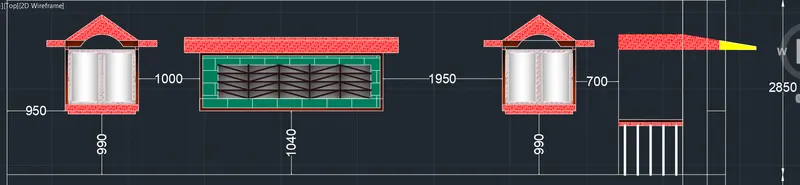
- Place it from a distance on all the three floors
- Now draw a room of size 4900 x 2500 on the terrace and inside room draw a door of size 900 x 2300
- Draw overhead tank of size 2575 x 1200 is drawn on top of the room as shown below
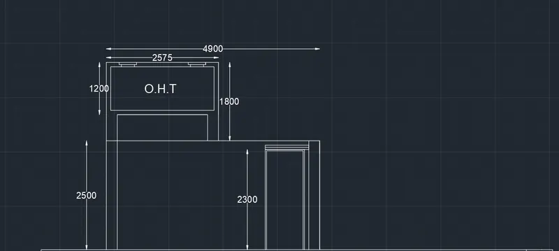
- Draw sunshades on other side of the building also with same dimension and hatch pattern
- Hatch the building walls using following patterns
- HATCH 7 : AR-B88 (COLOUR CYAN, SCALE 2 & COLOUR RED, SCALE 1)
- HATCH 8 : CROSS
- Specify the origin for the hatch pattern
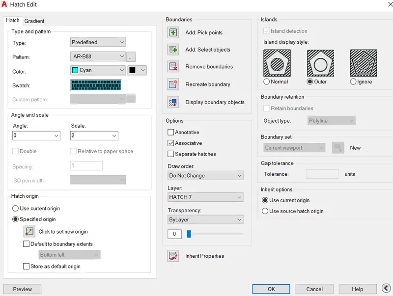
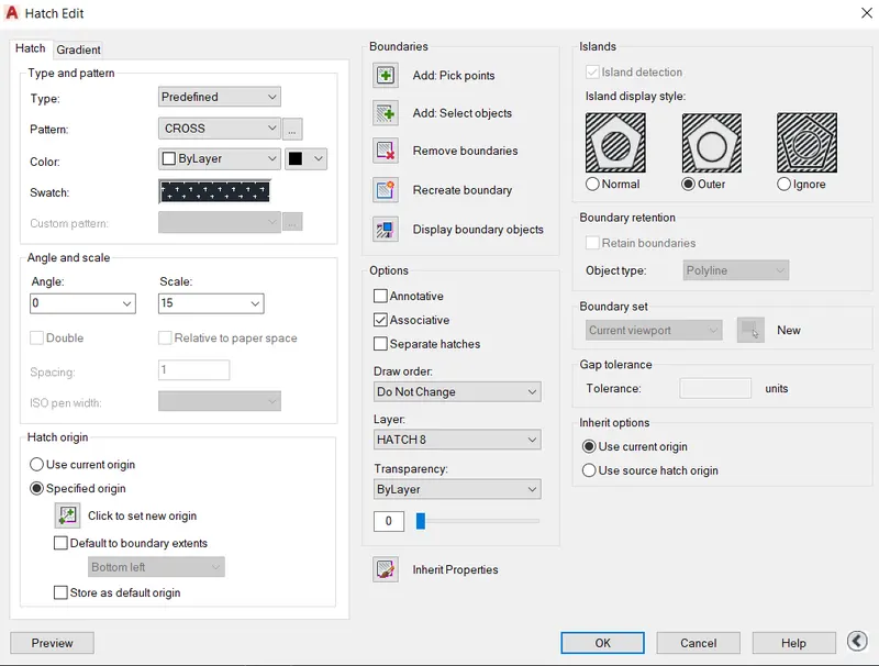
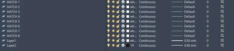
- Different layers are created ans assigned accordingly
RESULTS :
Elevation section of a building is created along with the windows, door and balcony. Different hatch patterns are assigned to the building
PROBLEM 3
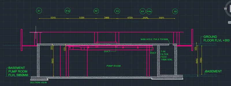
AIM : To create sectional view of industrial building and providing hatches using AutoCad
PROCEDURE :
- Set units to decimal
- Procedure for dimensions setting : Enter command dimstyle
Click on new and create a new style "STYLE 1"
1. Now go to Lines section and set the following:
Color, linetype and lineweight remians "ByBlock"
Suppress extension lines
2. Next go to symbols and arrow section and set the following:
Arrow size 150
3. Next go to Text and set the following:
Text style : Standard : Font style - Arial, Font name regular
Text color : Byblock
Text height : 300
Text placement both vertical and horizontal as centered, View direction as left to right
Offset from dimline : 1
Text aligment : Aligned with dimension
4. Next go to Fit and set the following:
Use overall scale of 1
5. Next go to Primary units and set the following:
Unit format : Decimal
Precision : 0 - Draw a rectangle of size 3275 x 180 mm
- Draw a rectangle of size 3042 x 500mm
- Draw a Xline on the top of previous rectangle
- Draw a column of size 450 x 5850mm (a) and draw similar column at a distance 22303mm (b) and 25495mm (c) taken from left side
- Draw rectangle of size 5790 x 510mm below the columns (b,c)
- Draw a x line at 300mm distance above these columns
- Above this line draw vertical projections of length 2180mm and draw a horizontal line above of length 28450mm
- Draw two vertical projections at extreme ends of size 230 x 4000mm and draw horizontal lines 5850mm based on given diagram
- Draw FLVL, basement level and groundlevels as per diagram with line type as "ACAD_ISO03W100"
- Using text tool write various texts given in the diagram with font size 300 and font style arial
- Using multi leader mention duct, manhole size and basement level with font height 300mm
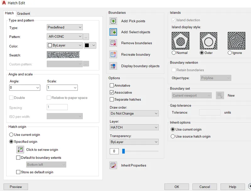
- Hatch the area as given in diagram using hatch tool. Hatch pattern used is AR-CONC at scale 1
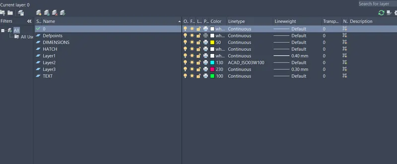
- Various layers are created and assigned accordingly
RESULT :
Sectional view of industrial buidling is created and hatch pattern, differents layers are assigned to the structure