Creating Kitchen layout, Hatching of Architectural elements and sectional view of an Industrial Building in AutoCad
1) AIM
To draw the following kitchen plan using autocad.
INTRODUCTION
This kitchen plan is created using autocad and the procedure is explained in detail in each steps and the commands are used in this drawing are.
COMMANDS USED IN THIS DRAWING
- L- LINE
- F8- ORTHO MODE
- GRIDMODE
- F10 - POLAR TRACKING
- ST - STYLE TEXT
- DT-SINGLE TEXT
- T- MULTITEXT
- C- CIRCLE
- CO-COPY
- M-MOVE
- T- TEXT
- TR- TRIM
- O-OFFSET
- F- FILLET
- D-DIMENSION STYLE
- REC-RECTANGLE
- DIMLINEAR
- DIMCONT
- DIMBASE
- LEADER
- QLEADER
- SC-SCALE
- LA-layers
- ADC-design center
- B-Block
- I-insert
- Xl-xline
- H-hatch
- xref
PROCEDURE
- open autocad file in windows desktop.
- a dialog box will open it shows startup from scratch.
- click the radio button imperial to start the project.
- in command box type gridmode to show the gridmode by typing 1 in the command box
- type F8 to get ortho on.
- type limmax to set the maximum layout.
- type llmits to set the layout.
- TYPE UN FOR UNITS and set to DECIMAL.
Step 1.
type xref
command to attach the refrence file from the pdf
press the edit snap points to snapping the points in the refrence file.
Type l- line
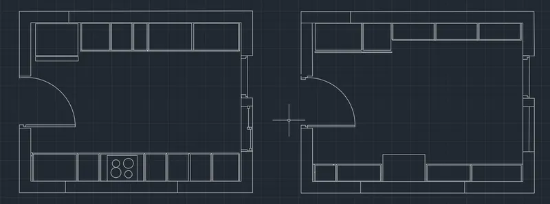
draw the line as per kitchen dimension.
snaping the points on the refrence file to line the object to easily draw.
using line command the following line of the kitchen plan is drawn as per dimension.
type o - offset the the line where ever needed.
after drawing the line command as per kitchen standard.
type sc- scale the object as per the dimension in refrence.
STEP 2
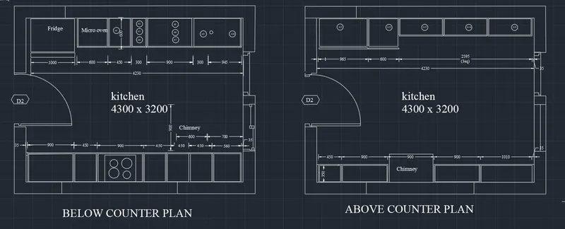
type t- multiline text to align in plan.
type -dimlinear- to set the dimension as per standard.
type - dimcont to continue the dimension as per standard.
After adding text and dimension as per plan
step 3
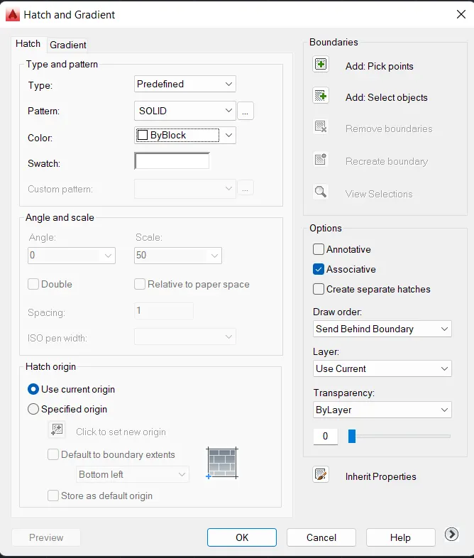
adding of Hatch command in the plan
type - H-hatch to hatch according to question.
set the origin to hatch in the plan.
as shown in fig below.
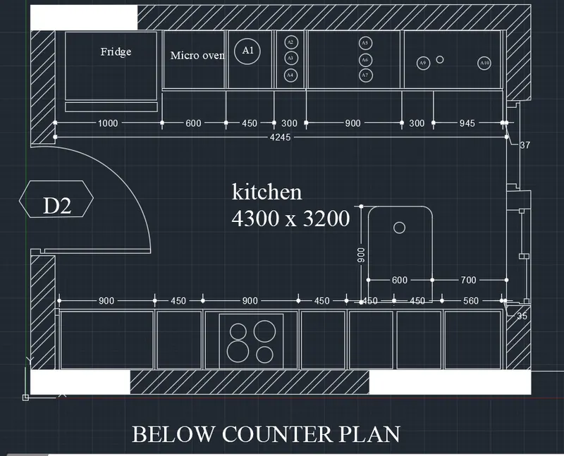
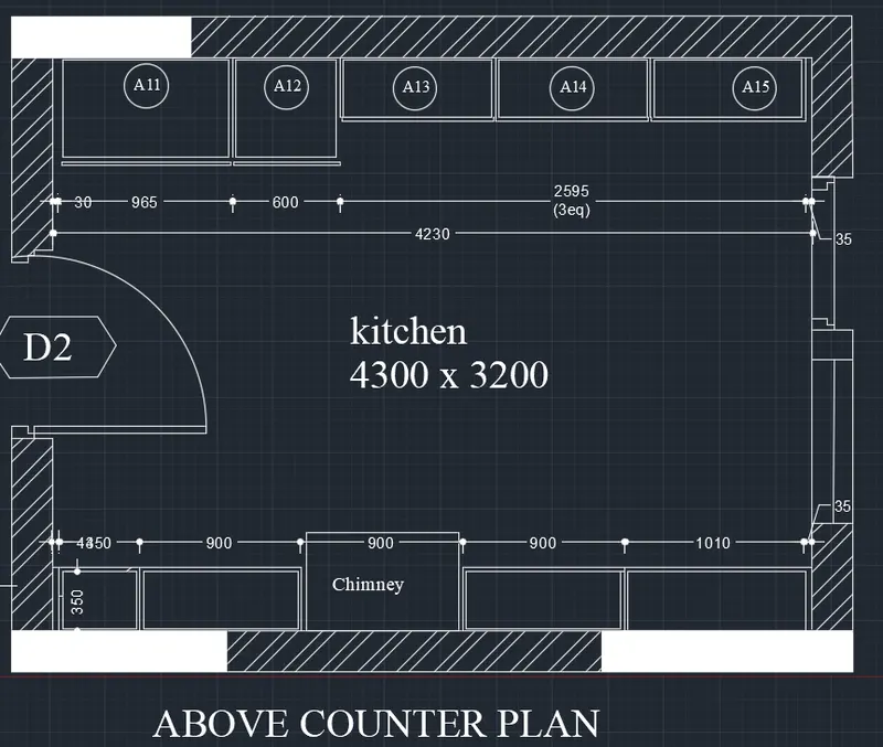
RESULT : THE folowing kitchen plan is done as per dimension is complted.
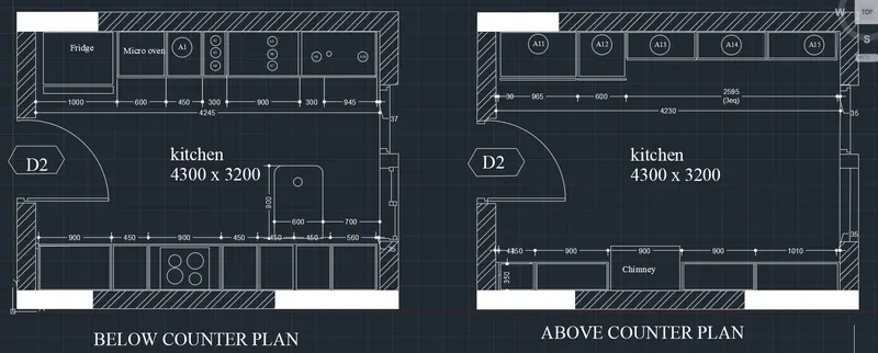
2)AIM
To draw the following elevation using autocad.
INTRODUCTION
This elevation is created using autocad and the procedure is explained in detail in each steps and the commands are used in this drawing are.
COMMANDS USED IN THIS DRAWING
- L- LINE
- F8- ORTHO MODE
- GRIDMODE
- F10 - POLAR TRACKING
- ST - STYLE TEXT
- DT-SINGLE TEXT
- T- MULTITEXT
- C- CIRCLE
- CO-COPY
- M-MOVE
- T- TEXT
- TR- TRIM
- O-OFFSET
- F- FILLET
- D-DIMENSION STYLE
- REC-RECTANGLE
- DIMLINEAR
- DIMCONT
- DIMBASE
- LEADER
- QLEADER
- SC-SCALE
- LA-layers
- ADC-design center
- B-Block
- I-insert
- Xl-xline
- H-hatch
- xref
PROCEDURE
- open autocad file in windows desktop.
- a dialog box will open it shows startup from scratch.
- click the radio button imperial to start the project.
- in command box type gridmode to show the gridmode by typing 1 in the command box
- type F8 to get ortho on.
- type limmax to set the maximum layout.
- type llmits to set the layout.
- TYPE UN FOR UNITS and set to DECIMAL.
Step 1.
using the xref commmand to refrence the file from the pdf.
type Xref to refrence the file.
crate the elevation plan using line command.
use the edit snap points to point the line in the command.
and use underlay option to set the line in a correct path.
use the refrence file to illusion the elevation as it is.
after using line command options of underlay is set to off so the line command is drawn and shown below.
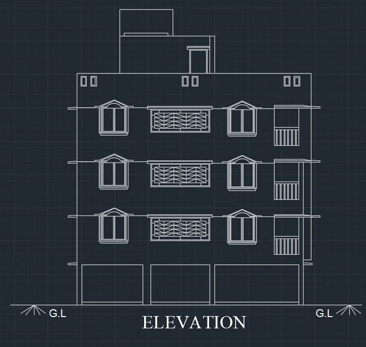
STEP 2
Adding of hatch command in the elevation plan.
type h- hatch command to hatch the properties according to elevation.
type H- hatch command and press t- setting of the hatch properties is shown below.
set the hatch command properties to change the color, type, set the origin, as shwon below.
STEP 3
AFTER ADDING OF PROPERTIES THE ELEVATION IS SHOWN BELOW.
BUILDING
in this hatch i have used the brick pattern to whole builidng .
and the color used in this propety is 242,113,114 as shown.
COLUMN
and i have used the for column property is conctrete. and the color used is 0,168,168 and the fill color is 199,200,202.
WINDOW
in this hatch property i have used the solid for the outer frame.
and for the glass color set the pattern as glass pattern.
and set the color for 90,142,211.
as shown in fig below.
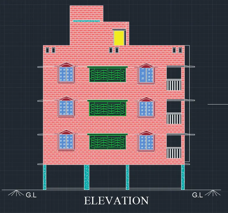
RESULT . the following elevation is drawn and the hatch command is used and completed.
3)
AIM
To draw the following sectional view using autocad.
INTRODUCTION
This sectional view is created using autocad and the procedure is explained in detail in each steps and the commands are used in this drawing are.
COMMANDS USED IN THIS DRAWING
- L- LINE
- F8- ORTHO MODE
- GRIDMODE
- F10 - POLAR TRACKING
- ST - STYLE TEXT
- DT-SINGLE TEXT
- T- MULTITEXT
- C- CIRCLE
- CO-COPY
- M-MOVE
- T- TEXT
- TR- TRIM
- O-OFFSET
- F- FILLET
- D-DIMENSION STYLE
- REC-RECTANGLE
- DIMLINEAR
- DIMCONT
- DIMBASE
- LEADER
- QLEADER
- SC-SCALE
- LA-layers
- ADC-design center
- B-Block
- I-insert
- Xl-xline
- H-hatch
- xref
PROCEDURE
- open autocad file in windows desktop.
- a dialog box will open it shows startup from scratch.
- click the radio button imperial to start the project.
- in command box type gridmode to show the gridmode by typing 1 in the command box
- type F8 to get ortho on.
- type limmax to set the maximum layout.
- type llmits to set the layout.
- TYPE UN FOR UNITS and set to DECIMAL.
STEP 1
using the xref commmand to refrence the file from the pdf.
type Xref to refrence the file.
use the scale option to fit in the scale after using xref file.
crate the elevation plan using line command.
use the edit snap points to point the line in the command.
and use underlay option to set the line in a correct path.
use the refrence file to illusion the elevation as it is.
after using line command options of underlay is set to off so the line command is drawn and shown below.
STEP 2
ADDING OF HATCH COMMAND
STEP 3
type T- text in the object.
type dimlinear to dimnesion the object as per the dimension.
using dimcont to continue the dimension the as per the dimension shown.
type ql - leader the object wherevere necessary.
column and slab
and i have used the for column property is conctrete pattern is used
and for the slab the solid pattern is used.
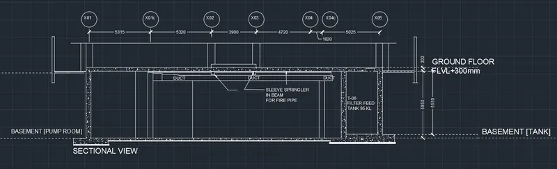
RESULT: the following sectional view is drawn as per the dimension and the hatches are used is completed.