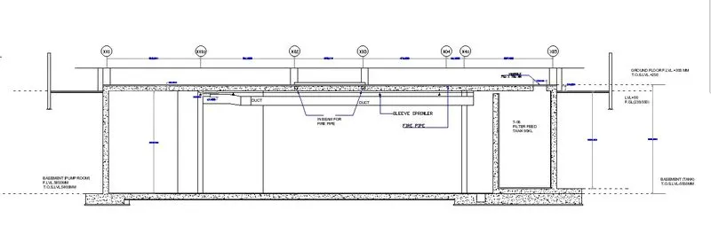
Creating Kitchen layout, Hatching of Architectural elements and sectional view of an Industrial Building in AutoCad
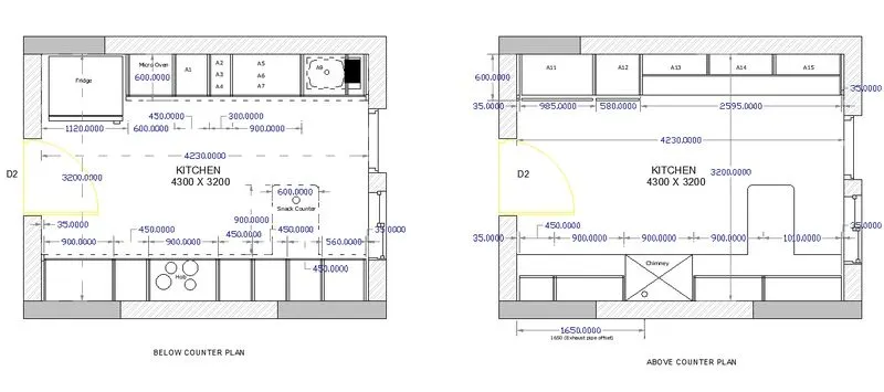
1.Create the layouts of the Kitchen and provide hatches pattern as shown. Also, use blocks wherever required. Provide appropriate dimensions in the plan. Assume the size of doors, appliances and others as per the standards.
- Start the Line command by clicking the Line button on the Draw panel on the Ribbon, or by entering L and then pressing Enter.
- Draw line segments by picking several random points.
- Terminate the command by pressing Enter, Esc, or the spacebar. Press Enter or the spacebar to repeat the Line command.
- Click Home tab Modify panel Trim. Select the objects to serve as cutting edges.
- Press Enter when you finish selecting the cutting edges. Select the objects to trim and press Enter a second time when you finish selecting the objects to trim.
- We can offset any object through a point or at a specified distance. We can create as many parallel lines and curves as with the help of the offset command.
- Place doors and windows.
- Go to the Draw panel on the Home tab. You will see a Hatch creation tab.
- Specify the pattern on the Pattern panel. Choose your desired method-Pick Points or Select Boundary Objects. After filling the area, hit Enter to apply the hatch.
- Give all dimensions to the elevation & Enter text by using the MTEXT command.
RESULT :
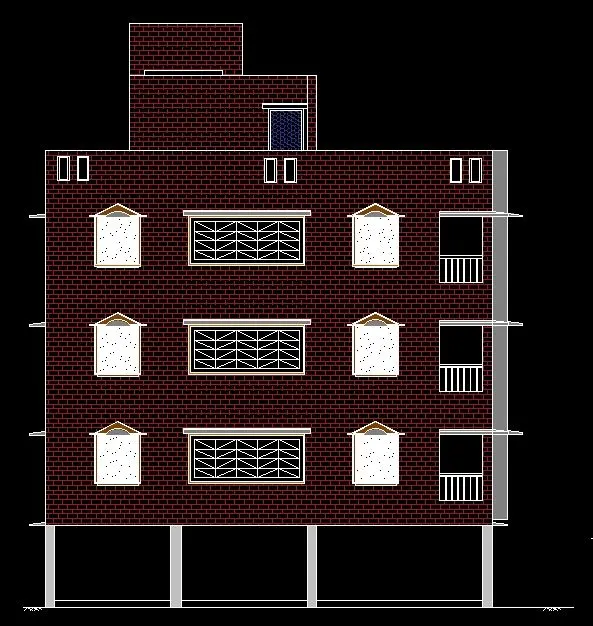
2. Create the elevation of the plan created in the Challenges 7 and apply proper hatch in the walls, doors, windows, and other architectural elements. Refer to the dimensions in Plans and sections in Challenges 7.
- Select the Trim tool by entering the ‘TR’ command in the command tab. Press ENTER.
- Select the Edge option, and click on No Extend.
- Select the unwanted lines.
- Press ‘Esc’ to cancel the TRIM command.
- Select the Offset tool by entering the ‘OFFSET’ command in the command tab.
- Create offsets according to the given drawing for the doors and windows, the height of the door is taken as 2100, and the height of the window is taken to be 600 for the smaller window and 1200 for the bigger window. Press Esc.
- Select the Trim tool by entering the ‘TR’ command in the command tab.
- Select the Edge option, and click on No Extend.
- Select the unwanted lines.
- Press ‘Esc’ to cancel the TRIM command.
- Assign the different objects to their respective layers.
- Select the Line tool by entering the ‘LINE’ command in the command tab.
- Draw the new section line. Press Esc.
- Go to Properties and change line type to long dash short dash.
- Select the Dimension tool by entering 'DIM' in the command line.
- Select the first point and second point of the object to be measured, then drag the dimension line to the desired location. Repeat for all the objects to be measured.
- Enter the 'MTEXT' command in the command line.
- Specify the start point of the text as required.
- Scale the text to the desired size.
- Copy the text box to wherever necessary.
- Enter ED in the command prompt and edit the text boxes as required. Click Enter and press Esc.
- In Annotate panel, go to Multileader Style Manager, select the standard option, click on Modify and make necessary changes, click OK, and Set current.
- Select the Multileader tool and create multi leaders wherever required as per the given drawing.
3. Create the section view of an industrial building as shown in Figure. Provide appropriate hatches and dimensions wherever required. Also, provide annotations to the drawing.
- Start the Line command by clicking the Line button on the Draw panel on the Ribbon, or by entering L and then pressing Enter.
- Draw line segments by picking several random points.
- Terminate the command by pressing Enter, Esc, or the spacebar. Press Enter or the spacebar to repeat the Line command.
- Click Home tab Modify panel Trim. Select the objects to serve as cutting edges.
- Press Enter when you finish selecting the cutting edges. Select the objects to trim and press Enter a second time when you finish selecting the objects to trim.
- We can offset any object through a point or at a specified distance. We can create as many parallel lines and curves as with the help of the offset command.
- Place doors and windows.
- Go to the Draw panel on the Home tab. You will see a Hatch creation tab.
- Specify the pattern on the Pattern panel. Choose your desired method-Pick Points or Select Boundary Objects. After filling the area, hit Enter to apply the hatch.
- Give all dimensions to the elevation & Enter text by using the MTEXT command.