Creating a Floor plan, Footing detail and Isometric view using AutoCad
To obtain the following geometry the AUTOCAD Software is used. The procedure and results are as follow.
Commands used in this challenge
- Line (L)
- Polyline (Pol)
- Rectangle (Rec)
- Chamfer (ch)
- Offset (o)
- Isometric Views
- Copy (co)
- Fillet (f)
- Dimension (dim)
- C.S.ISOLATED FOOTING
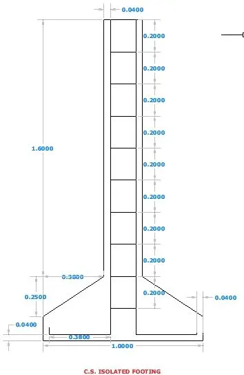
PROCEDURE :
- In the command press L to select Line command to draw line on the work space.
- Pickup a point and move the cursor to <0 and enter 1
- Move the cursor to <90 and enter 0.25
- Move the cursor to <90 and enter 0.15
- In command entered next point as @-0.38,0.25
- Move the cursor to <90 and enter 1.60 and press esc
- Select line command and again go to the starting point and
- Move the cursor to <90 and enter 0.15
- In command entered next point as @0.38,0.25
- Move the cursor to <90 and enter 1.60
- Move the cursor to <0 and enter 0.04
- Move the cursor to <270 and enter 0.38 and picked midpoint from adjacent lines extend the current line and press esc.
- Select mirror tool and select the inner lines as objects and pick middle base point as first point and drag it to the top to get mirror image.
- Select line command and pick the top starting point of the inner line of dimension 1.96 and click the adjacent line of same dimension.
- Select offset and select the line is drawn recently and give offset distance as 0.20 and select multiple as option and move cursor downwards and click to do 9 offset one by one.
- C.S.LOAD BEARING WAWLL OVER SPREAD FOOTING
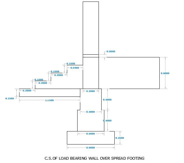
Procedure:
- In the command press L to select Line command to draw line on the work space.
- Pickup a point and move the cursor to <0 and enter 0.90
- Move the cursor to <90 and enter 0.25
- Move the cursor to <180 and enter 0.40
- Move the cursor to <180 and enter 0.05
- Move the cursor to <90 and enter 0.40
- Move the cursor to <180 and enter 0.05
- Move the cursor to <90 and enter 1.75
- Then select Mirror option and select all the vertical lines and pick a base point in the middle and take next point perpendicularly upwards to mirror the objects
- Select line command and click it in the top left portion where the point is over 0.40.
- Move the cursor to <270 and enter 0.15
- Move the cursor to <180 and enter 1.15
- Move the cursor to <90 and enter 0.15
- Move the cursor to <0 and close
- Select line command and click it in the left corner in the top of the drawing and
- Move the cursor to <0 and enter 0.30
- Move the cursor to <90and enter 0.15
- Move the cursor to <0 and enter 0.30
- Move the cursor to <90 and enter 0.15
- Move the cursor to <0 and enter 0.30
- Move the cursor to <90 and enter 0.15
- Move the cursor to <0 and enter 0.30
- Move the cursor to <90 and enter 0.15
- From join the other side of the line by clicking.
- Press esc and select offset tool and give offset distance as 0.05 and select this above line and offset it.
- Again, select line tool and join the top part of the both vertical lines.
- C.S LOAD BEARING WALL SHOWING FOOUNDATION DETAILS
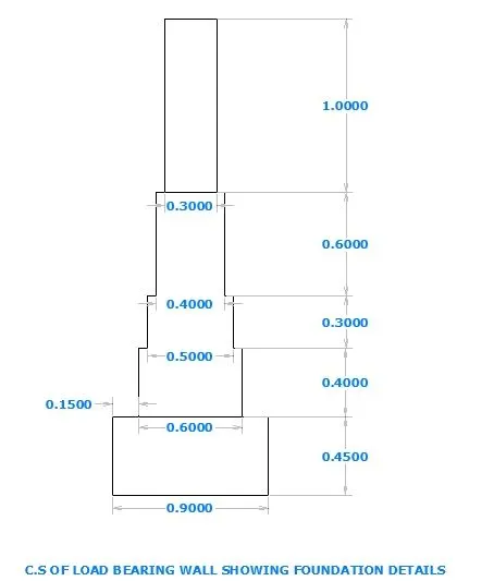
Procedure:
- In the command press L to select Line command to draw line on the work space.
- Pickup a point and move the cursor to <o and enter 0.90
- Move the cursor to <0 and enter 3.60
- Move the cursor to <90 and enter 0.45
- Move the cursor to <180 and enter 0.15
- Move the cursor to <90 and enter 0.40
- Move the cursor to <180 and enter 0.05
- Move the cursor to <90 and enter 0.30
- Move the cursor to <180 and enter 0.05
- Move the cursor to <90 and enter 0.60
- Move the cursor to < 180 and enter 0.05
- Move the cursor to <90 and enter 1
- Select mirror tool from ribbon and select the object as all line except the base horizontal line of dimension 0.90.
- Click the middle base point and drag the cursor to the top end to form a mirror.
- Finally select line tool and join the top vertical line.
- ISOMETRIC VIEW OF GABLE WALL
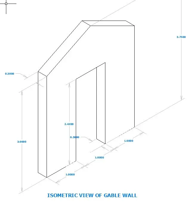
Procedure:
- In the command press L to select Line command to draw line on the work space.
- Click Isometric Drafting button in the status bar to draw Isometric drawings with Ortho button on, which is also in status bar.
- Pickup a point and select Isometric left and move the cursor to the left and enter 0.30
- Move cursor to the top and enter 3
- Move the cursor to the right and enter 0.30
- And click to the starting point
- Pickup from the same point and select Isometric top and move the cursor to the right and enter 1
- select Isometric right and move the cursor to the top and enter 2.42
- Move the cursor to the right and enter 1
- Move the cursor to the bottom and enter 2.42
- Move the cursor to the right and enter 1
- Move cursor to the top and enter 3
- Change to Isometric left and move cursor to the left and enter 0.30
- Press esc and select Line command and draw a temporary line connecting the bottom of the wall and pick midpoint
- Move the cursor to the top and enter 4 by selecting Isometric left
- Move the cursor to the left and enter 0.30
- Press esc and select Line command and switch off the Ortho mode and connect the roof by selecting top middle portion to the sides.
- Finally click bottom temporary wall line which created earlier and erase it.
- ISOMETRIC VIEW OF STEPS
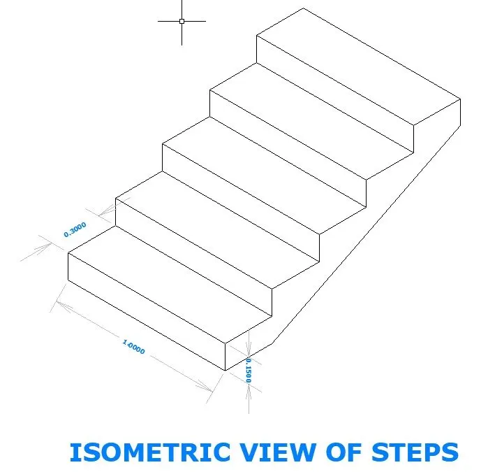
Procedure:
- In the command press L to select Line command to draw line on the work space.
- Click Isometric Drafting button in the status bar to draw Isometric drawings with Ortho button on, which is also in status bar.
- Pickup a point and select Isometric left and move the cursor to the left and enter 1
- By pressing Fn+F5 change the mode to Isometric right and move cursor to the top and enter 0 .15 and again change the mode to Isometric left and move the cursor down and click close.
- Change mode to Isometric right and click the top left corner of the riser and move it to right and enter 0.30
- Move cursor to the top and enter 0.15
- Move cursor to the right and enter 0.30
- Move cursor to the top and enter 0.15
- Move cursor to the right and enter 0.30
- Move cursor to the top and enter 0.15
- Move cursor to the right and enter 0.30
- Move cursor to the top and enter 0.15
- Move cursor to the right and enter 0.30
- Move cursor to the top and enter 0.15
- Move cursor to the right and enter 0.30
- Change mode to Isometric left and enter 1
- Change mode to Isometric top and move cursor to the left and enter 0.30
- Change mode to Isometric right and move cursor down and enter 0.15
- Move cursor to the left and enter 0.30
- Move cursor to the down and enter 0.15
- Move cursor to the left and enter 0.30
- Move cursor to the down and enter 0.15
- Move cursor to the left and enter 0.30
- Move cursor to the down and enter 0.15
- Move cursor to the left and enter 0.30
- And click the end point.
- Change mode to Isometric left and draw a horizontal line connecting both sides of thread and riser.
- Press esc and select line command and move cursor down and enter 0.15.
- Click Ortho off and line an inclined line endpoint near the first step thread point and connect it to the starting point of the staircase.
- LINE DIAGRAM OF A TWO BEDROOM BUILDING
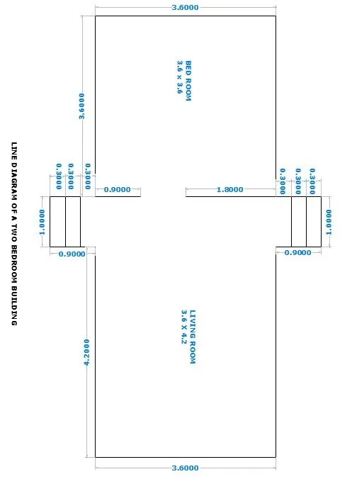
Procedure:
- In the command press L to select Line command to draw line on the work space.
- Pickup a point and move the cursor to <o and enter 0.90
- Move the cursor to <0 and enter 3.60
- Move the cursor to <90 and enter 0.45
- Move the cursor to <180 and enter 0.15
- Move the cursor to <90 and enter 0.40
- Move the cursor to <180 and enter 0.05
- Move the cursor to <90 and enter 0.30
- Move the cursor to <180 and enter 0.05
- Move the cursor to <90 and enter 0.60
- Move the cursor to < 180 and enter 0.05
- Move the cursor to <90 and enter 1
- Select mirror tool from ribbon and select the object as all line except the base horizontal line of dimension 0.90.
- Click the middle base point and drag the cursor to the top end to form a mirror.
- Finally select line tool and join the top vertical line.