Creating Kitchen layout, Hatching of Architectural elements and sectional view of an Industrial Building in AutoCad
Aim:
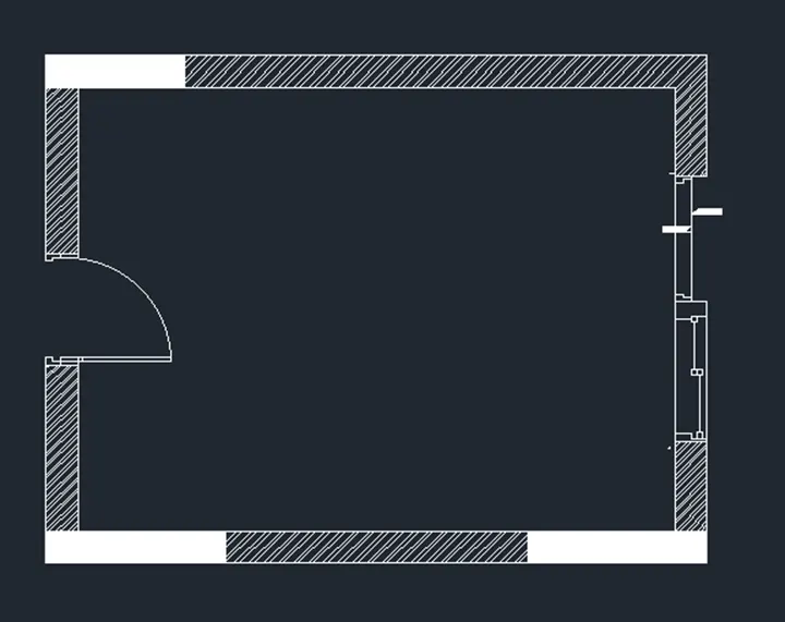
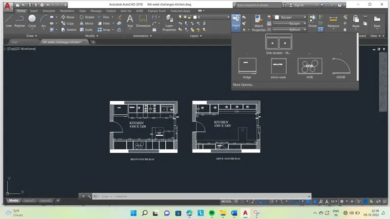
To Create the Kitchen Layout as shown in the Figure .
Introduction :
Various command used while Sketching :
- Line command
- Unit command
- Lim max command
- XL command
- Zoom command
- Arc command
- Trim command
- Text command
- Extent command
- Fillet command
- Rectangle command
- Circle command
- Copy command
- LT command
- Dimension command
- Layer command
- Offset command
- Limits command
- Block command
- Insert command
- Rename command
PRODUCTRE :
STEP 1 :
- GO to START MENU ,select AutoCAD 2018.
- Enter “UNITS” command in the command tab.
- Open “ Drawing units “ dialogue box , Type as “Decimal ” and precision as 00
- Then click units scale to “ millimetres ”
- Click “OK”.
- Enter “ LIM MAX” command in the command tab.
- Enter new value for Lim max as 30000’.
- Enter “zoom” command in the command box.
- Enter “All” command in the command box.
- Enter “LIMITS” command in the command box.
- Specify lower left corner as “0,0”
- Specify right corner as “28000,28000”
- Enter “zoom “ command in the command box.
- Enter “ALL” command in the command box.
Step 2:
CREATING Kitchen:
- Creating counter plan
- Enter “REC” command in the command box.
- Give a value of “4300x 3200mm” rectangle box.
- Enter “Offset” command in the command box.
- Give a value of “230mm” wall thickness in outside of the box.
- Creating left cabinet and fridge
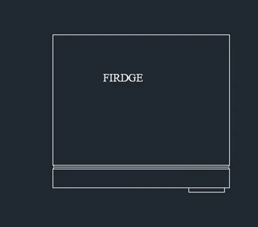
- Draw fridge by using rectangle command
- Enter “OFFSET” command in the command box.
- Give value of “1000mm” abd start drawing slabs showing cabinet below.
- Enter “OFFSET” command in the command box.
- Give a value of “600mm” for cabinet below for microwave oven and give an offset of “20mm”
- Enter “OFFSET” command in the command box.
- For width of cabinet give an offset of “600mm” and “20mm” inside and 10mm offset for thickness.
- Enter “OFFSET” command in the command box.
- From “600mm” offset give an offset for A1
- Enter “OFFSET” command in the command box
- Give a value of “300mm” offset for A2,A3,A4.
- Enter “OFFSET” command in the command box.
- Give a value of “300mm” offset for A5,A6,A7.
- Enter “OFFSET” command in the command box.
- Give a offset value of “35mm” from the left and create hinge.
- Enter “OFFSET” command in the command box.
- Give a offset value of “20mm” thickness inside .
- Draw a right cabinet and hob:
- Enter “OFFSET” command in the command box.
- give a value of “35mm” from the left and crating hinge .
- for width of cabinet give a value of “600mm” and “20mm” inside
- Enter “OFFSET” command in the command box.
- Give a value of “10mm” offset for thickness.
- Enter “OFFSET” command in the command box.
- From “35mm” give an offset value of “900mm”
- Give a offset value of “450mm” from the “900mm” and again offset a distance of “900mm”
- Enter “OFFSET” command in the command box.
- Give a offset of distance “450mm” three times from the previous offset
- From the right side offset “35mm” for hinge and rest distance of will be “630mm” which shows the top cabinet .
- Hob is a drawn by rectangle and circle tool in the plan of third cabinet.
- Enter “OFFSET” command in the command box.
- Draw the snack counter by giving offset distance of “700mm” from the left side of wall and “900mm” from the “600mm” width of cabinet
- Enter “FILLET” command in the command box.
- Give a value of “10mm” radius
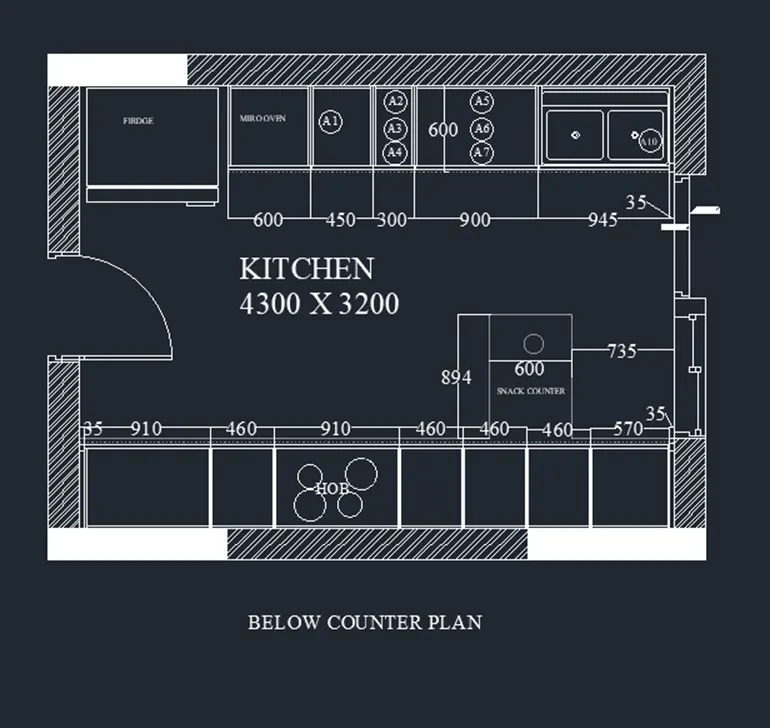
- Draw the counter plan:
- Copy the wall of below counter plan
- Draw the right side counter .
- Enter “OFFSET” command in the command box.
- Draw a width of “350mm” from the wall to inside offset “20mm”
- Enter “OFFSET” command in the command box.
- Offset a distance of “35mm” from the left side of wall.
- Enter “OFFSET” command in the command box.
- Give a value of “450mm” for the top of the cabinet .
- Enter “OFFSET” command in the command box.
- Give a value of “900mm” , 3times for next cabinet .
- Enter “OFFSET” command in the command box.
- For the second “900mm”.
- Enter “REC” command in the command box.
- Draw a rectangle value of “1650mm” from the left side of wall.
- Draw a circle for chimney .
- Draw a left side counter .
- Enter “OFFSET” command in the command box.
- Give a offset value of “35mm”


- Enter “OFFSET” command in the command box.
- Give a value “600mm” offset as width from horizontal wall.
- Enter “OFFSET” command in the command box.
- Give a value of “10mm” offset to show the door.
- Enter “OFFSET” command in the command box.
- From the 35mm hinge offset of “965mm” to the right
- Enter “OFFSET” command in the command box.
- From that offset of “600mm” for the next cabinet
- Enter “OFFSET” command in the command box.
- Give a offset value of “35mm” from the right
- Rest of distance is “2665mm” which is divided intro 3equal parts A13, A14, A15.
- Enter “OFFSET” command in the command box.
- Give a value of “20mm” on both sides of divisions and also “20mm” in front for doors.
- Enter “OFFSET” command in the command box.
- give a value of “10mm” in backside for thickness .
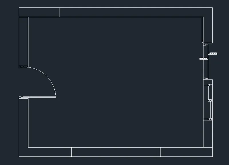
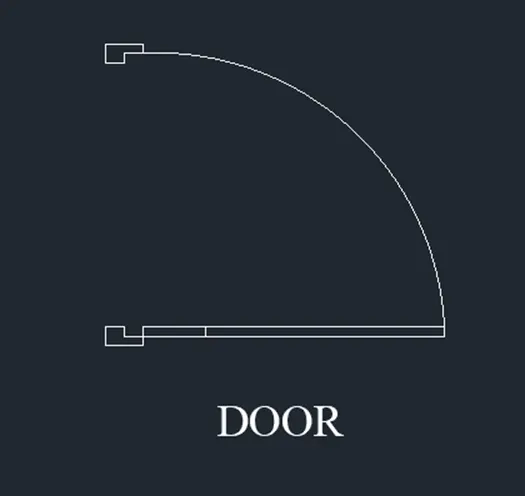
- draw a doors , sliding doors and windows
- sizes of doors is “900mm” width of high is”20mm”
- window of width “900mm”
- Enter “OFFSET” command in the command box.
- For the sliding door take “200mm” of offset from the window and giving an opening of “900mm”
- Enter “DIMLINER” command in command box.
- Dimension all the rooms and wall thickness.
- Enter “MTEXT” command in command box .
- Give a text hight as “200mm” and style as
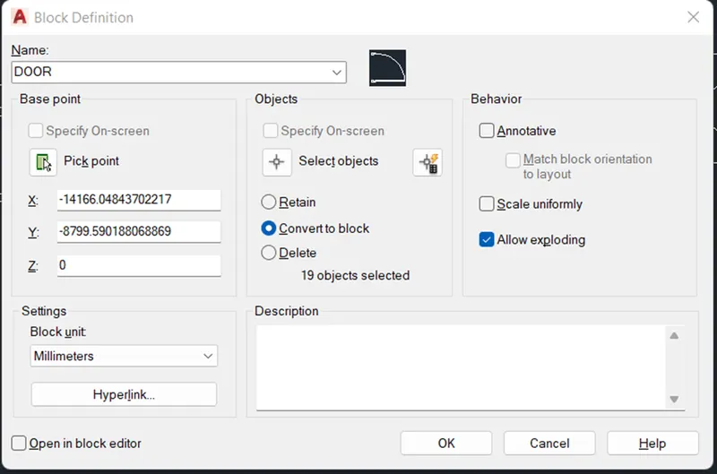
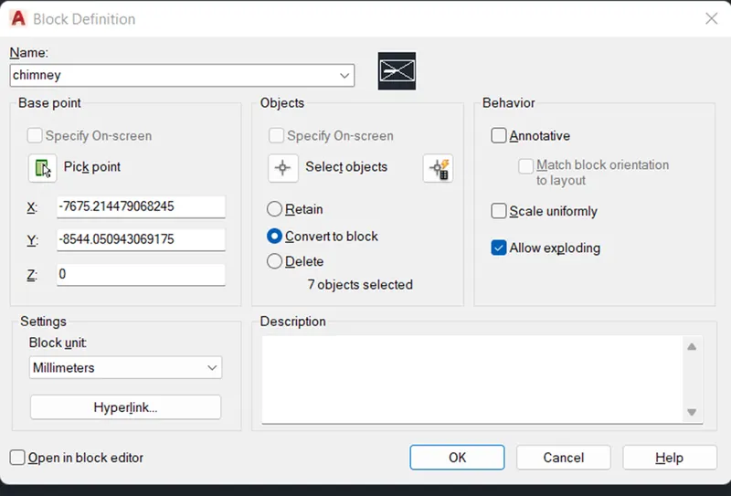
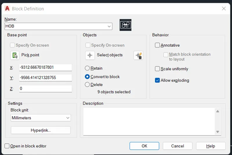
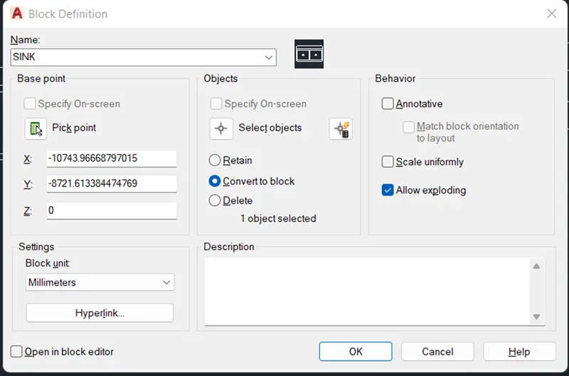
- Enter “BLOCK” command in the command box.
- U will “BLOCK DEFINITION “ dialoge box.
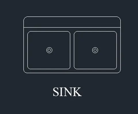
- Give a name as “DOOR ,MIRCO OVEN , SINK , FRIDGE ,AND HOB”
- Then click “SELECT OBJECTS”
- Then click “CONVERT TO BLOCK”
- Select “PICK PIONT “
- Give a description if you want to note .
- Click “OK”
- Enter “INSERT” command in the command
- Insert the blocks as per the drawing .
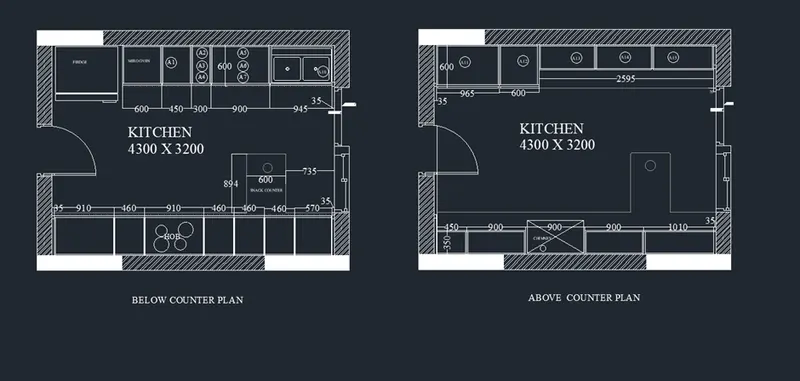
- Finally shown the results in down .
RESULT :
AIM:
TO create the elevation of the plan created in challenges 7 and apply hatch in the walls , doors and windows and other architectural elements.
Introduction :
Various command used while Sketching :
- Line command
- Unit command
- Lim max command
- XL command
- Zoom command
- Arc command
- Trim command
- Text command
- Extent command
- Fillet command
- Rectangle command
- Circle command
- Copy command
- LT command
- Dimension command
- Layer command
- Offset command
- Limits command
PRODUCTRE :
STEP 1 :
- GO to START MENU ,select AutoCAD 2018.
- Enter “UNITS” command in the command tab.
- Open “ Drawing units “ dialogue box , Type as “Decimal ” and precision as 00
- Then click units scale to “ millimetres ”
- Click “OK”.
- Enter “ LIM MAX” command in the command tab.
- Enter new value for Lim max as 30000’.
- Enter “zoom” command in the command box.
- Enter “All” command in the command box.
- Enter “LIMITS” command in the command box.
- Specify lower left corner as “0,0”
- Specify right corner as “28000,28000”
- Enter “zoom “ command in the command box.
- Enter “ALL” command in the command box.
STEP 2:
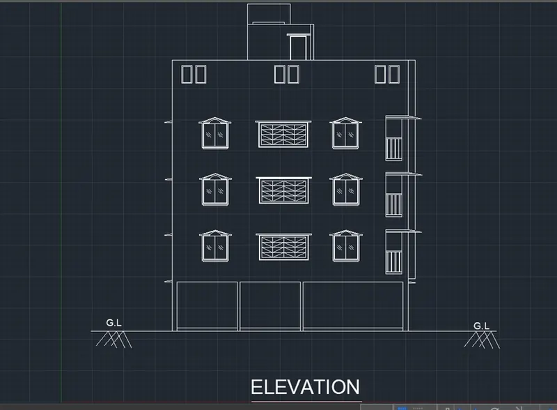
CREATING ELEVATION :
- Enter “XL “ (OR) “ X line” command in the command box.
- Specific a point as “Vertical” command in the command box.
- Move the line to somewhere , where you want
- Than click “ESC” command in the command box.
- Enter “XL “ (OR) “ X line” command in the command box.
- Specific a point as “Horizontal” command in the command box.
- Move the horizontal line to close to the vertical line.
- Than click “ESC” command in the command box.
- Enter “Line” command in the command box .
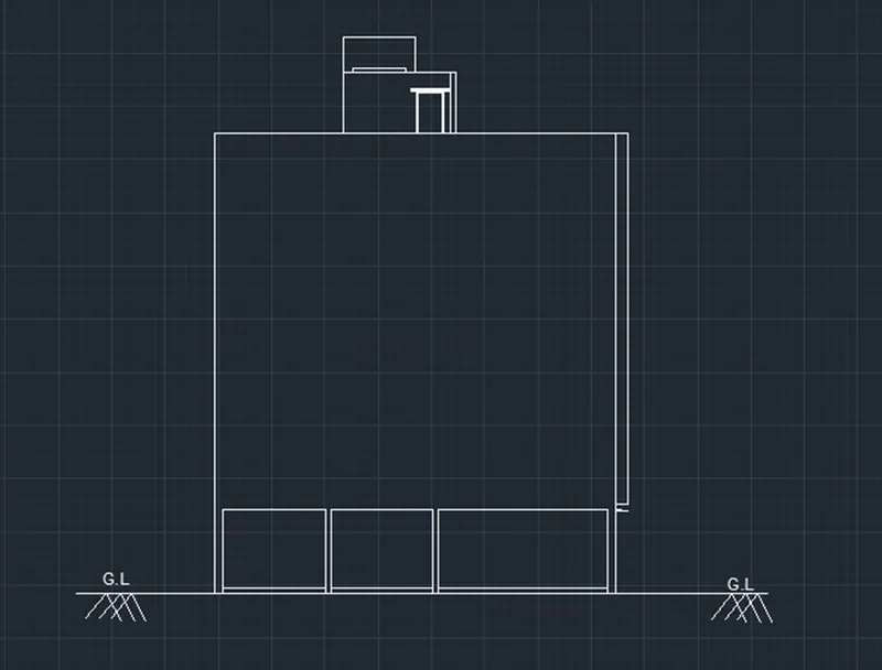
- Give a value of “11000mm” horizontally
- Enter “Line” command in the command box .
- Next we have to draw another line from the previous line vertically with length of “16388mm”
- Enter “Line” command in the command box .
- Next again draw the line form the previous line with the length of “11000mm” horizontally backwards from the previous line.
- Enter “Line” command in the command box .
- Now draw the line from the first line and last line was drawn previously
- Enter “OFFSET” command in the command box.
- Give a value of “250mm” for external wall
- And give a ground level thickness is “200mm” and “150mm”
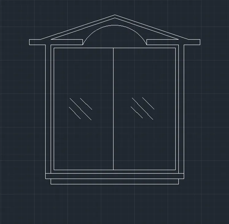
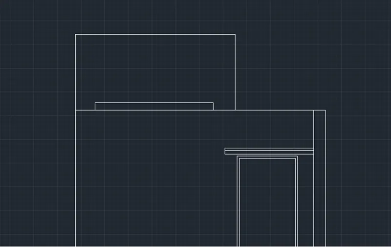
- Next we a to draw window in their requires places in 1st and 2nd and 3rd floor
- Enter “OFFSET” command in the command box.
- Give a value of “1200mm” for “HOD”
- Next we have to draw the sunshade in the upside of the window protect from the sunlight,
- Enter “MTEXT” command in the command box.
- Give a value of “150mmm” or “200mm” for the text hight ,
- W1- 900 X 1200mm
- W – 600 x 1200mm
- W2- 1000x 1200mm
- W3-1500 x1200mm
- W4- 500x500mm
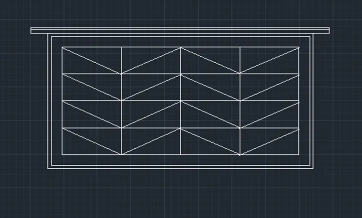
- D- 1000X 2100mm
- D1- 700 X2100mm
- D2 -900 X2100mm
- Give a texts as per the drawing and show the result as per the drawing.
RESULT :
AIM:
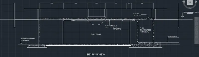
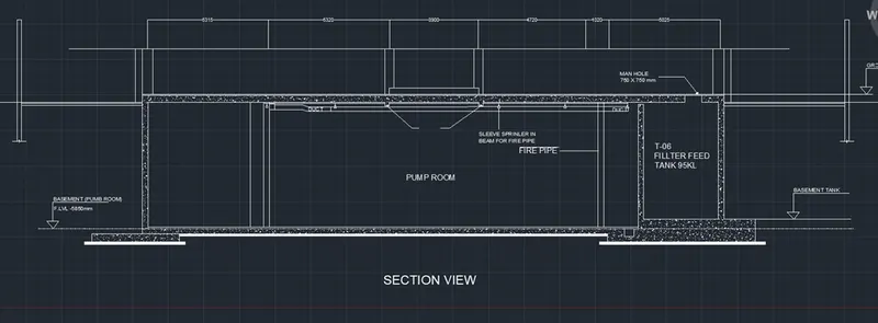
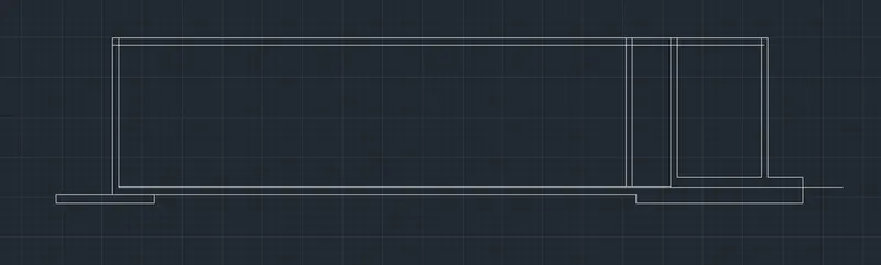
TO create the section view of industrial building as shown figure .
Introduction :
Various command used while Sketching :
- Line command
- Unit command
- Lim max command
- XL command
- Zoom command
- Arc command
- Trim command
- Text command
- Extent command
- Fillet command
- Rectangle command
- Circle command
- Copy command
- LT command
- Dimension command
- Layer command
- Offset command
- Limits command
PRODUCTRE :
STEP 1 :
- GO to START MENU ,select AutoCAD 2018.
- Enter “UNITS” command in the command tab.
- Open “ Drawing units “ dialogue box , Type as “Decimal ” and precision as 00
- Then click units scale to “ millimetres ”
- Click “OK”.
- Enter “ LIM MAX” command in the command tab.
- Enter new value for Lim max as 30000’.
- Enter “zoom” command in the command box.
- Enter “All” command in the command box.
- Enter “LIMITS” command in the command box.
- Specify lower left corner as “0,0”
- Specify right corner as “28000,28000”
- Enter “zoom “ command in the command box.
- Enter “ALL” command in the command box.
STEP 2:
CREATING ELEVATION :
- Enter “XL “ (OR) “ X line” command in the command box.
- Specific a point as “Vertical” command in the command box.
- Move the line to somewhere , where you want
- Than click “ESC” command in the command box.
- Enter “XL “ (OR) “ X line” command in the command box.
- Specific a point as “Horizontal” command in the command box.
- Move the horizontal line to close to the vertical line.
- Than click “ESC” command in the command box.
- Enter “offset” command in the command box
- Give a value of “5850mm” from the previse horizontal line
- Enter “offset” command in the command box
- Give a value of “5550mm” from the previse horizontal line
- Enter “offset” command in the command box
- Give a value of “25300mm” from the previse vertical line
- Enter “LINE” command in the command box .
- Give a value of “200mm” for the pipe line.
- Enter “LINE” command in the command box .
- Give a value of “200mm” for the duck.
- Enter “LINE” command in the command box .
- Give a value of “700mm X 700mm” for the manhole
- Enter “HATCH” command in the command box .
- Give “CONCRETE HATCHES “ in the drawing .
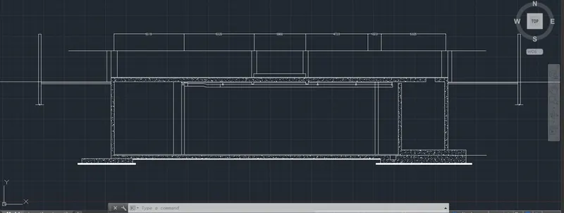
- Enter “DIMLINER” command in the command box.
- Show the dimension as per the drawing.
- Enter “TEXT” command in the command box .
- Give a “TEXTS” as per the drawing .
- Finally show the results as per the drawing .
RESULT: