Creating Kitchen layout, Hatching of Architectural elements and sectional view of an Industrial Building in AutoCad
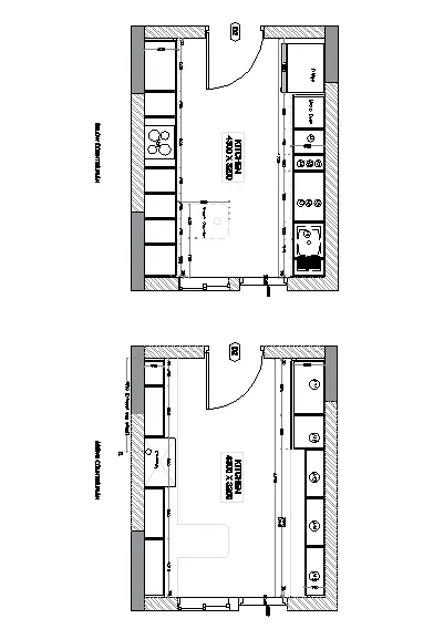
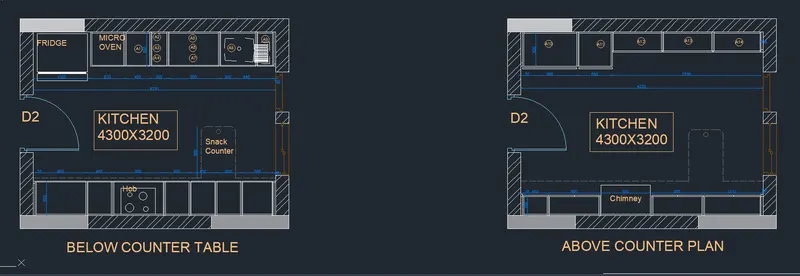
1Q:Create the layouts of the Kitchen and provide hatches pattern as shown. Also, use blocks wherever required. Provide appropriate dimensions in the plan. Assume the size of doors, appliances and others as per the standards.
AIM:
PROCEDURE:
Type UN and press enter
Under Drawing Units, select decimal
Now the lower limit is set to 0, 0 and the upper limit to 25000, 25000
Type Z enter to zoom and A enter to all
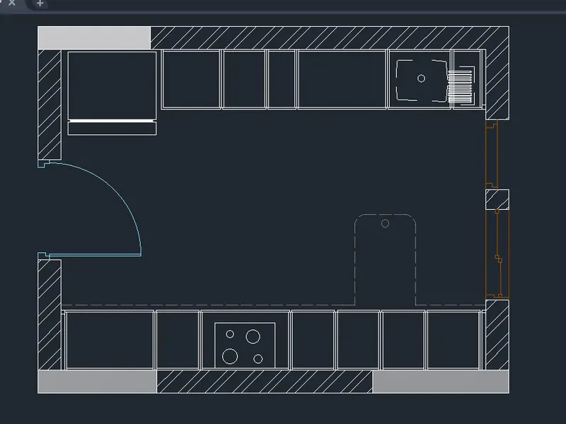
Draw a rectengle of 4300x3200 and by using the OFFSET command 230mm ouside the rectangle
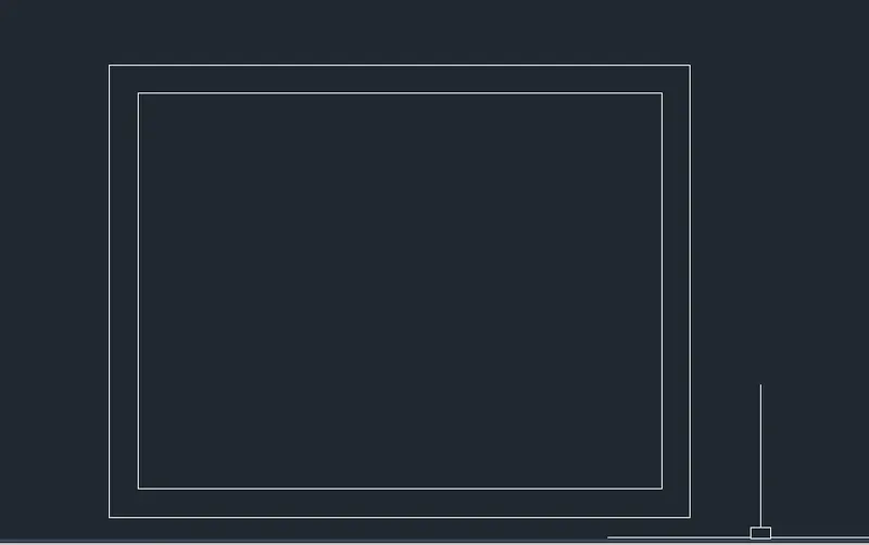
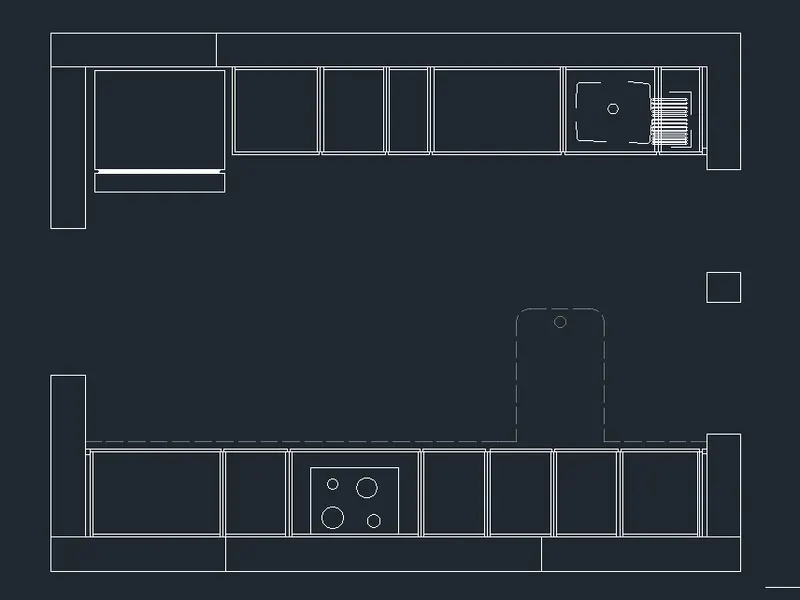
Now using the OFFSET command 600 mm inside the both side of the rectangle and by using OFFSET command draft the kitchen as shown below
By using the H command HATCH the walls of the kitchen.
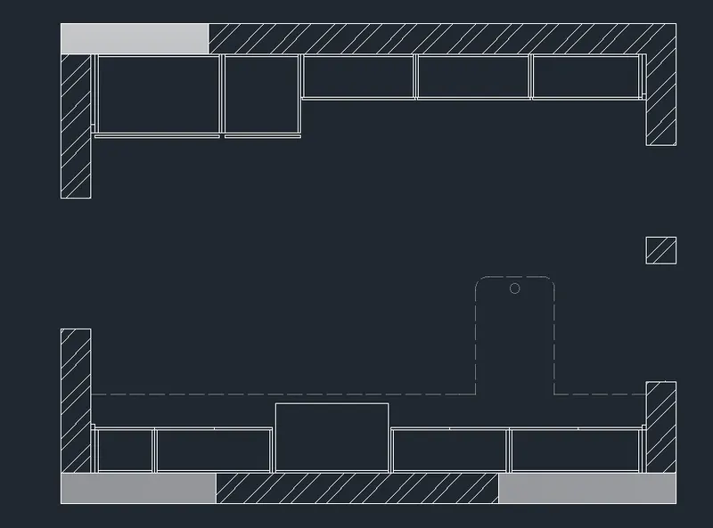
Now using the LINE,CIRCLE,TRIM command draw the doors and windows of the kitchen.
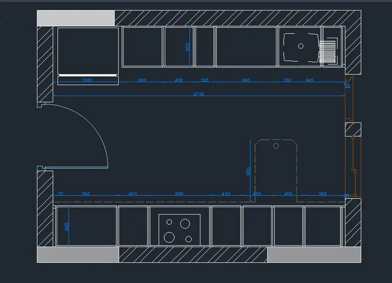
Now using the DIMLIN, DIMCONT command show the required dimensions of the kitchen
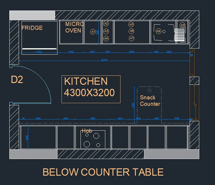
By the MTEXT command text the required information on the drawing
Now using the same procedure draw the above counter line
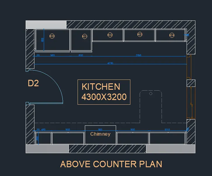
RESULT: Kitchen Layout is completed as shown in the Figure
2Q:
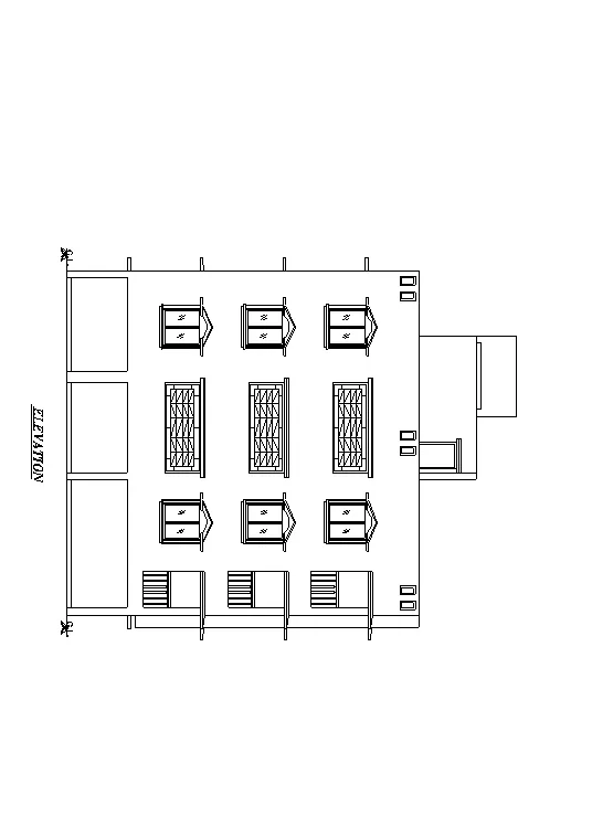
AIM:Create the elevation of the plan created in the Challenges 7 and apply proper hatch in the walls, doors, windows, and other architectural elements. Refer to the dimensions in Plans and sections in Challenges 7
PROCEDURE:
Type UN and press enter
Under Drawing Units, select decimal
Now the lower limit is set to 0, 0 and upper limit to 1000, 1000
Type Z enter to zoom and A enter to all
Using the construction line command XL horizontal and vertical lines was created from challenge 7 building.
By using the OFFSET command SILL level as 900 and LINTEL level 2100 set the offset and TRIM command trim the unwanted lines and by using the COPY command copy the remaining positons.
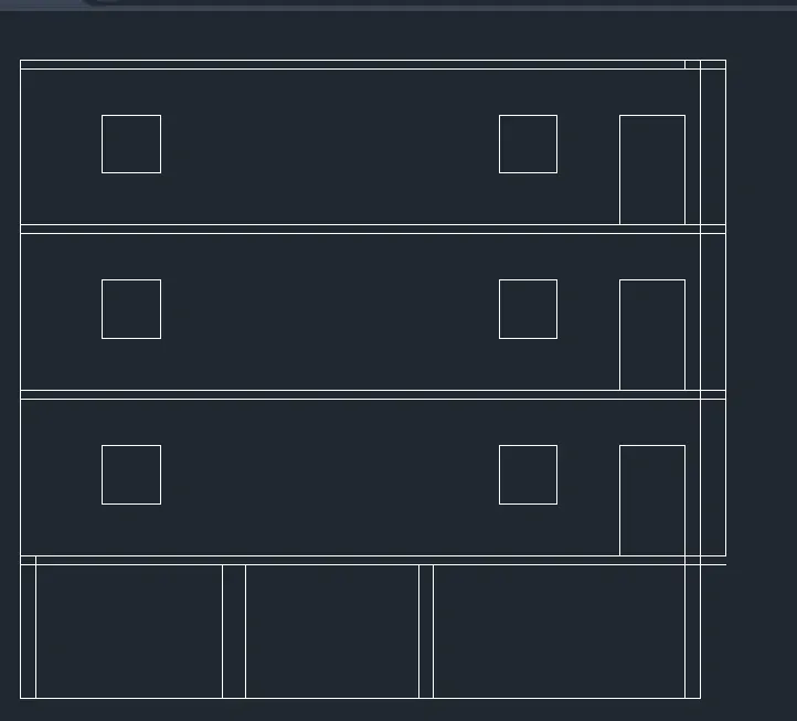
Go to the Draw panel on the Home tab. Find the hatch icon in the bottom right corner.
In "Hatch creation” tab. Go to its Properties panel and choose the Hatch type that you would like to insert. Here Solid and Pattern type was used.
In hatch settings "create separate hatches" options was selected, so that each entity will remain as an individual if any correction was to be made, else it would have to be done from first.
Pick points options was was to hatch the area. The “Pick Points” will determine a boundary around the specified point.
After filling the area, hit “Enter” to apply the hatch.
Use different HATCH fillters for different area.
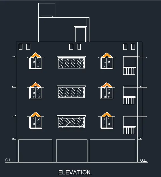
RESULT:Create the elevation of the plan created in the Challenges 7 and apply proper hatch in the walls, doors, windows, and other architectural elements is COMPLETED.
3Q:
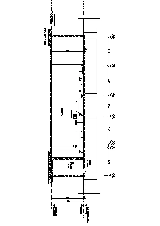
AIM:
Create the section view of an industrial building as shown in Figure. Provide appropriate hatches and dimensions wherever required. Also, provide annotations to the drawing.:
PROCEDURE:
Type UN and press enter
Under Drawing Units, select decimal
Now the lower limit is set to 0, 0 and upper limit to 1000, 1000
Type Z enter to zoom and A enter to all
To create a Layer
In the Layer Properties Manager, click New Layer.
A layer name is added to the layer list.
Enter a new layer name as Walls by typing over the highlighted layer name.
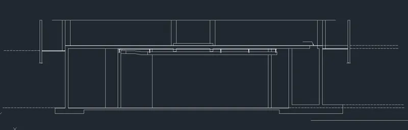
Now using the line,rectangle, offset, trim,fillet commands all the wall portions was completed.
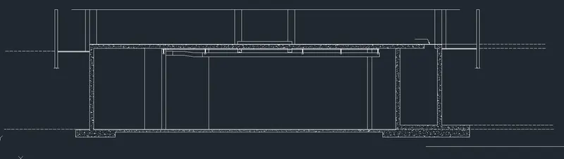
Hatching of walls
Go to the Draw panel on the Home tab. Find the hatch icon in the bottom right corner.
In "Hatch creation” tab. Go to its Properties panel and choose the Hatch type that you would like to insert. Here pattern type was used for hatching. 8
In hatch settings "create separate hatches" options was selected, so that each entity will remain as an individual if any correction was to be made, else it would have to be done from first.
Pick points options was was to hatch the area. The “Pick Points” will determine a boundary around the specified point.
After filling the area, hit “Enter” to apply the hatch.
A new layer is now created, named as texts and a suitable colour is selected and this layer is made as the default.
Now using the MTEXT all the texts was made and the following image is obtained.
A new layer is now created, named as Dimensions and a suitable colour is selected and this layer is made as the default.
Now using the Dimlin the dimensions was plotted and the following image is obtained
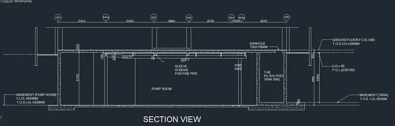
RESULT: Created the section view of an industrial building as shown in Figure and COMPLETED.