Creating Kitchen layout, Hatching of Architectural elements and sectional view of an Industrial Building in AutoCad
QUESTION NO. 1
ANSWER:
AIM:Create the layouts of the Kitchen and provide hatches pattern as shown. Also, use blocks wherever required. Provide appropriate dimensions in the plan. Assume the size of doors, appliances and others as per the standards.
INTRODUCTION: IN THIS DRAWING WE HAVE TO DRAW THE KITCHEN LAYOUT WITH THE USE OF HTCHING COMAND
- FOR DRAWING SIZE 4300X3200
- ASSUME DOOR SIZE D2= 915MM WIDTH
- WALL THICKNESS 230MM
START THIS DRAWING FIRST OF ALL WE HAVE TO DO SOME SETTINGS ACCORDING THE DRAWING -
DRAWING LINK :
https://web.autocad.com/acad/me/sid/shares/drawings/6cd3e611-d6f3-4d26-9945-42c7e2e8c133/editor
SOFTWARE SETTINGS
SETTINGS - OPEN AUTOCAD
- SET DEFAULT SETTINGS - METRIC UNIT (mm)
- SELECT A TEMPLATE - ACCORDING TO DRAWINGS
- SELECT A WIZAED - ADVANCED SETUP
- UNITS - DECIMAL
- ANGLE - DECIMAL DEGREES
- ANGLE MEASURE - ACCORDING TO PLAN
- ANGLE DIRECTION - COUNTER CLOCKWISE
- AREA - ACCORDING TO PLAN
After this enter "D" for dimetion unit and set primary unit DECIMAL set precision 0
MODES -
- GRID ON BY F7 'CONTROL+G'
- USE ORTHO MODE FOR STRAIGHT 90 DEGREE ACCRDING NEED(F8)
- ON POLAR TRACKING (F10) SET ANGLE (15,30,45)
- OBJET SNAP TRACKING (F11)
- OBJECT SNAP (F3)
- TRANPARANCY ON WHEN YOU NEED
OTHER DATA:
- SIZE OF THE KITCHEN
- WALL THICKNESS
PROCEDURE:
TO DRAW THE LAYOUT PLAN WE FOLLOW THE FOLLOWING STEPS : -
STEP-1
Make layer:
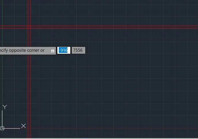
For starting drawing make new for wall put coloe= red select line type or line weight.
- For draw the layout of the kitchen first of all take construction line and put it horizontal.
- againg take construction by command xl and put it vertical .
- Now take offset 230 mm for outer wall
- it take verticlly and horizontally.
STEP-2
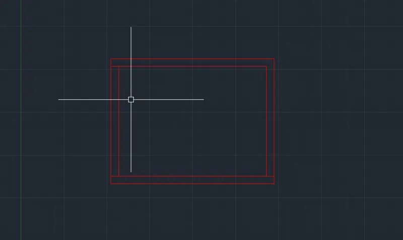
- Now Go to offset command and take offset 4300 from vertical line and 3200 from horizontal line
- again take 230 mm offset for wall
- use trim or delete command to erase the unwanted line.
STEP-3
For Internal blocks of the kitchen make new layer put color yellow and set line weight , line type.
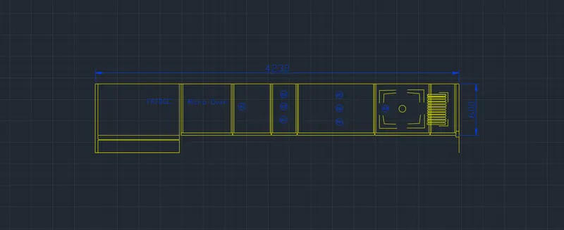
- Now we start to draw the upper blocks of the kicthen
- To draw the block take horizontal line 4230 and take offset 600
- draw vertical line both corner of 600 mm .
- Start taking offsets from one corner 1000mm
- again take vertical offset 600 from last
- Again take offset 450 from last
- Again take offset 300 from last
- Again take offset 900 from last
- Again take offset 300 from last
- Again take offset 645 from last
- Again take offset 35 from last
STEP-4
- Now Draw the fridge portion door and spacing with the help off line and offset command.
- Take the spcing 15 mm from center line of the object both side . and arrange it with the help of trim and line command.
- Go to New layer put name Dimention and Text object , blocks name and show dimention.
STEP-5
CREAT BLOCK
- Now go to the final part o the drawing
- select all the autocad drawing object than enter block command in the command bar.
- Now put the name KITCHEN BLOCK-A in the name box
- pik up point of this object
- than go to description part and describe about this
- now press okk
- this object is converted in to the block.
STEP-6
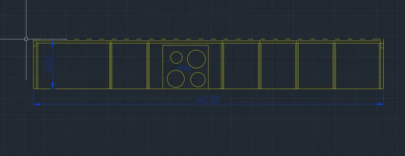
- Now we start to draw the Below block of the kicthen
- To draw the block take horizontal line 4230 and take offset 600
- draw vertical line both corner of 600 mm .
- Start taking offsets from one corner 1000mm
- again take vertical offset 600 from last
- Again take offset 35 from last
- Again take offset 900from last
- Again take offset 450 from last
- Again take offset 900 from last
- Again take offset 450 from last
- Again take offset 450 from last
- Again take offset 450 from last
- Again take offset 560from last
- Again take offset 35 from last
STEP-7
- Now Draw the Snake counter , widht of it 600mm lenght is 900mm it its 700mm from wall
- Now Draw the fridge portion door and spacing with the help off line and offset command.
- Take the spacing 15 mm from center line of the object both side . and arrange it with the help of trim and line command.
- Go to layer Dimention and Text object , blocks name and show dimention.
STEP-8
CREAT BLOCK
- Now go to the final part o the drawing
- select all the autocad drawing object than enter block command in the command bar.
- Now put the name KITCHEN BLOCK-B in the name box
- pik up point of this object
- than go to description part and describe about this
- now press okk
- this object is converted in to the block.
STEP-9
BLOCK INSERT
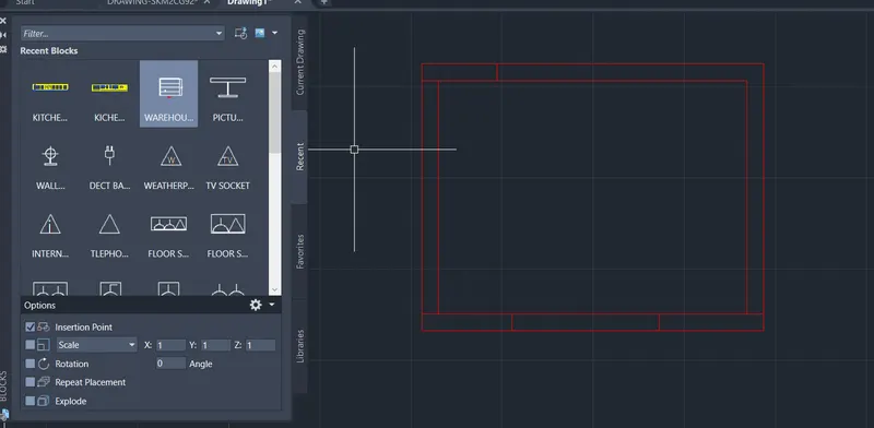
- Now put 'insert' on the command bar and take Kitchen blcoks-A and put it in the kitchen upper side.
STEP-10
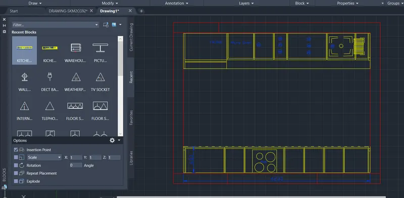
- Again put 'insert' on the command bar and take Kitchen blcoks-B and put it in the kitchen Below side.
- width the help of line creat the door and widow of the kitchen widh of the doorvis 915 mm and of the wimdow is also 900mm
STEP-11
CREAT HATCHING
- No We are starting hatching , hatching is the process of filling or showing the drawing with diffrent patterns and colors
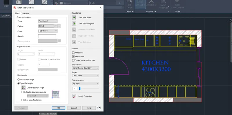
- Go to commmand bar put hatch , select type predefine and for wall put ANSI32 AND pattern color gray .
- pic-up the hatching and fillit on the walls portion
- again Take hatching and select solid put it inn the wall where required.
STEP-12
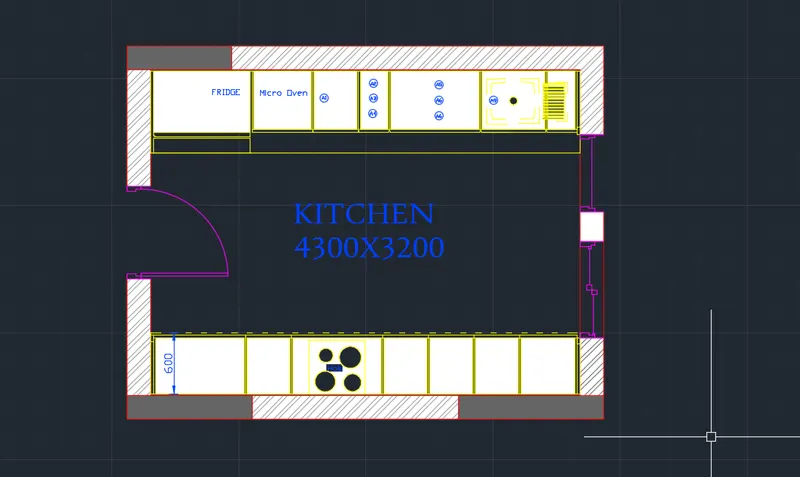
- Again take hatching and select solid , color while and put it on the block of the kithen .
- also put it below block and kitchen block potions
- with the help of text command write the size and name of the drawing.
STEP-13
BELOW COUNTER PLAN
- To draw the below counter plan copy the simple plan of the ktichen
- Now we start to draw the upper blocks of the kicthen
- To draw the block take horizontal line 4230 and take offset 600
- draw vertical line both corner of 35 mm .
- Start taking offsets from one corner 965mm
- again take vertical offset600 from last
- Again take offset 2595from last
- Again take offset 35 from last
- Again take offset 872 MEANS The 2595 divided into three equale parts.
- Now we start to draw the Below block of the kicthen
- To draw the block take horizontal line 4230 and take offset 350
- draw vertical line both corner of 35 mm .
- Start taking offsets from one corner 450mm
- again take vertical offset 900 from last
- Again take offset 900from last
- Again take offset 900from last
- Again take offset 1010 from last
- Again take offset 35 from last `
STEP-14
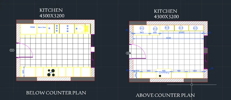
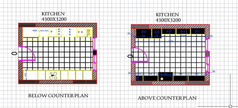
CREAT HATCHING
- No We are starting hatching , hatching is the process of filling or showing the drawing with diffrent patterns and colors
- Go to commmand bar put hatch , select type predefine and for wall put ANSI32 AND pattern color gray .
- pic-up the hatching and fillit on the walls portion
- again Take hatching and select solid put it inn the wall where required.
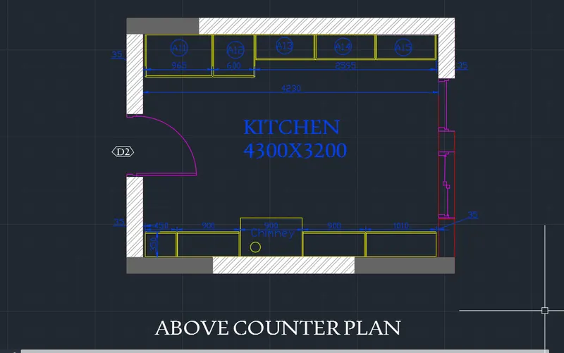
RESULT: ALL THE GIVEN PLAN, SECTIONS AND ELEVATION DRAWINGS ARE COMPLETED WITH THE PROPER DIMENTION TECHNIQUES DIMENTION STYLE .AFTER MAKING THE DRAWING FINAL DRAWING SCREENSHOTS ARE ATTACHED WITH RESULTENT DRAWING .THE LINK OF THE DRAWING OF AUTOCAD IS ALSO ATTACHED FOR REFRENCE.
AUTOCAD DRAWING LINK
https://web.autocad.com/acad/me/sid/shares/drawings/6cd3e611-d6f3-4d26-9945-42c7e2e8c133/editor
https://web.autocad.com/acad/me/sid/shares/drawings/6cd3e611-d6f3-4d26-9945-42c7e2e8c133/editor
DRAWINGS:-
BELOW COUNTER PLAN:
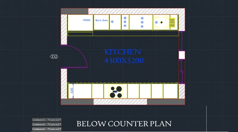
ABOVE COUNTER PLAN:
OTHER HATCHING DRAWINGS:
QUESTION NO. 2
ANSWER:
AIM: Create the section view of an industrial building as shown in Figure. Provide appropriate hatches and dimensions wherever required. Also, provide annotations to the drawing.
INTRODUCTION: IN THIS PLAN WE HAVE TO DRAW THE ELEVATION OF THE CHALANGE NO -7 DRAWING. For Creat the elevation of this , we have to go to the challange No.-7 For the Plan , because we know that for draw any elevation we want to simple plan of the drawing , and plan of this elevation is in the challange no-7
START THIS DRAWING FIRST OF ALL WE HAVE TO DO SOME SETTINGS ACCORDING THE DRAWING -
DRAWING LINK :
https://web.autocad.com/acad/me/sid/shares/drawings/f0551adb-0224-42ac-8905-d621984a3af3/editor
SOFTWARE SETTINGS
SETTINGS - OPEN AUTOCAD
- SET DEFAULT SETTINGS - METRIC UNIT (mm)
- SELECT A TEMPLATE - ACCORDING TO DRAWINGS
- SELECT A WIZAED - ADVANCED SETUP
- UNITS - DECIMAL
- ANGLE - DECIMAL DEGREES
- ANGLE MEASURE - ACCORDING TO PLAN
- ANGLE DIRECTION - COUNTER CLOCKWISE
- AREA - ACCORDING TO PLAN
After this enter "D" for dimetion unit and set primary unit DECIMAL set precision 0
MODES -
- GRID ON BY F7 'CONTROL+G'
- USE ORTHO MODE FOR STRAIGHT 90 DEGREE ACCRDING NEED(F8)
- ON POLAR TRACKING (F10) SET ANGLE (15,30,45)
- OBJET SNAP TRACKING (F11)
- OBJECT SNAP (F3)
- TRANPARANCY ON WHEN YOU NEED
OTHER DATA:
- SIZE OF THE KITCHEN
- WALL THICKNESS
PROCEDURE:
TO DRAW THE LAYOUT PLAN WE FOLLOW THE FOLLOWING STEPS : -
STEP-1
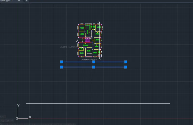
- For Creat the elevation of this , we have to go to the challange No.-7 For the Plan , because we know that for draw any elevation we want to simple plan of the drawing , and plan of this elevation is in the challange no-7
- Now We insert the plan in the drawing to draw the elevation.
- Now take line and put it horizontally.
STEP-2
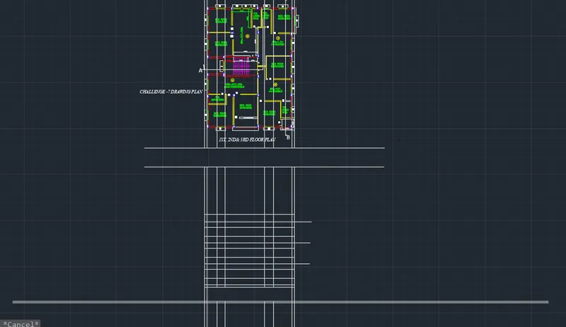
- Now start taking vertical projection line from the plan to the elevation.
- lines take from wall corner , window corner , balcany corner , and outside chajja
- Now divided the elevation into third flor building widththe help of offset command
- Take offset 150 from ground level
- Again 2450 from last offset
- Again take offset 2850 from last offset
- Again take offset 2850 from last offset
- Again take offsset 2850 from last offset
- Now Take ioffset 1000 from last offset for parapet wall
- again take 1500offset for stair building
- From First floor take offset take offset 915mm for window height from flooring area.
- Again Takke 1220 mm for height of the window
- this offset take three times means till third floor.
STEP-3
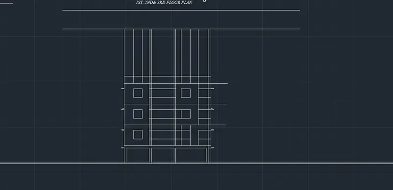
- Now we use the trim command and trimm all the unwanted line .
- trim all the lines outside of the window. trim it both side.
- and also draw the front balcany of the elevation.
CHAJJA
- Now we start drawing of chajja of the windows.
- For Chajja of the window go to layer Properties an make new layer 'Chajja'
- Set Line Type- Center line, Line color , And Line weight of the line .
- Than start Drawing to draw the chajjar.
- Take Width of the chajja is 75mm to 115 and lenght 350mm.
- and Draw with CHajja layer.
WINDOW CREATION
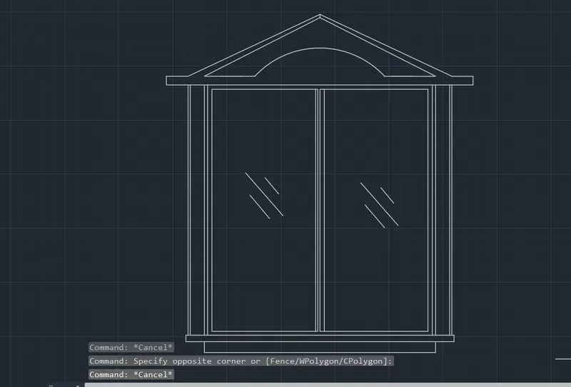
- For Creat the the window go to the line command and take horizontal offset of 50mm
- Again take offset off 75mm
- Take vertical offset and takee it 150mm and take it both side of the frame
- take spacing 20mm for setteled the glass .
- Now creating the arc take arc three point and choose three point and draw line upword
- take two lines from corner and join .
- For glass zigzag use line command.
STEP-5
BLOCK CREAT OF THE WINDOW
- Now go to the final part of the drawing
- Select all the autocad drawing object than enter block command in the command bar.
- Now put the name window(1220x1220) in the name box
- Pik up point of this object
- Than go to description part and describe about this
- Now press okk
- This object is converted in to the block.
INSERT BLOCK:
- We start to inserting of the window block in the elavation part
- For this type insert in the command bar
- Now select window1220x1220 and put it cneter of the window anda again take window nad put this window is put all the window area.
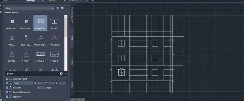
STEP-6
- Insert all the window with the help of snaping insertion point intersection poin of geometric center point
- use trim command to trim all the unwanted line.
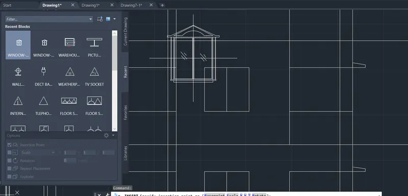
STEP-7
- For This portion of the elevvation take offset of 150 mm four side from the projection lines
- now take 50mm offset out side and draw the wall corner 300mm both side take offset 30 mm upper side.
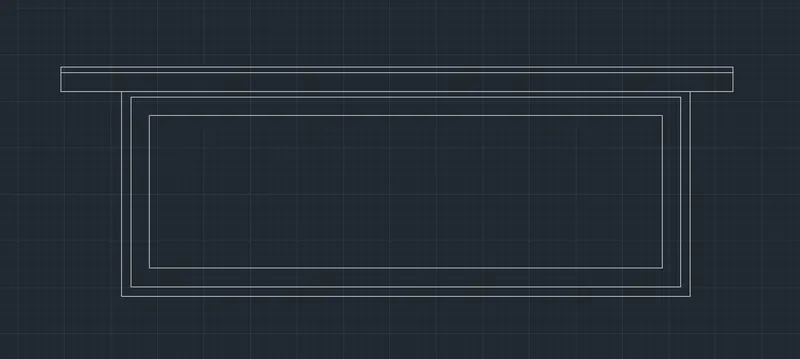
STEP-7
SIDE GALLRY:
- take offset of 75 mm from chajja level .
- again take 75mm and draw the chajja in the corner.
- Now draw the pipe of the gallry
- And draw lines. For gallry spacing
- Now Take copy command and copy this all object and put it first floor and second floor.
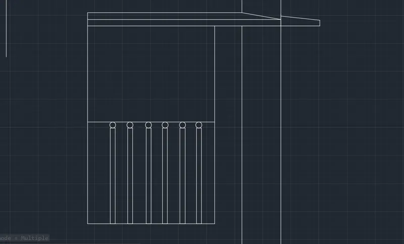
STEP-9
TERRACE AREA:
- now We star to drawing th terrace building.
- To draw this take offset of 1500 from parapet wall
- again take offset 300 mm
- again take offset 1500mm
- Now Draw the door of the terrace
- For door take offset of 230 from column
- again take offset of 60 mm
- give door width 900 mm
PARAPET WALL DESIGN:
- For paper wall design take rec command and draw a rectangle.
- take ofset command and takeoffset of 50 mm internal side
- copy this and put it with the distance of 250 mm
- again copy all tha two design and put it ths the help of elevation .
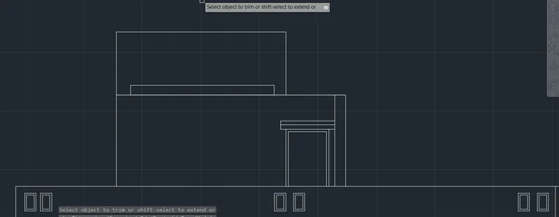
STEP-10
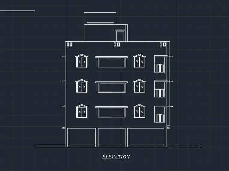
ELEVATION DRAWING:
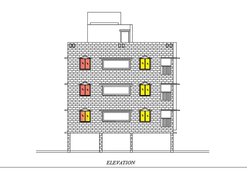
DIFFRENT HATCHING DRAWING:
CREAT HATCHING
- No We are starting hatching , hatching is the process of filling or showing the drawing with diffrent patterns and colors
- Go to commmand bar put hatch , select type predefine and for wall put ANSI32 AND pattern color gray .
- pic-up the hatching and fillit on the walls portion
- again Take hatching and select solid put it inn the wall where required.
HATCHING DRAWING:
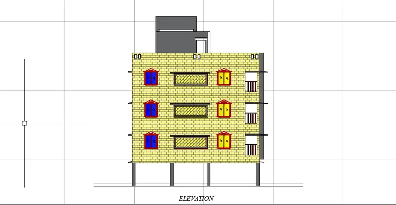
RESULT: THE GIVEN ELEVATION DRAWINGS ARE COMPLETED WITH THE PROPER DIMENTION .AFTER MAKING THE DRAWING FINAL DRAWING SCREENSHOTS ARE ATTACHED WITH RESULTENT DRAWING .THE LINK OF THE DRAWING OF AUTOCAD IS ALSO ATTACHED FOR REFRENCE.
AUTOCAD DRAWING LINK
https://web.autocad.com/acad/me/sid/shares/drawings/f0551adb-0224-42ac-8905-d621984a3af3/editor
DRAWING:
QUESTION NO. 3
ANSWER:
AIM:Create the section view of an industrial building as shown in Figure. Provide appropriate hatches and dimensions wherever required. Also, provide annotations to the drawing.
INTRODUCTION: IN THIS DRAWING WE HAVE TO DRAW THE SECTION PART AND AFTER DRAWING ALSO FILLING HATCHING AND USE ANNOTATIONS.FOR START THIS DRAWING FIRST OF ALL WE HAVE TO DO SOME SETTINGS ACCORDING THE DRAWING -
DRAWING LINK :
https://web.autocad.com/acad/me/sid/shares/drawings/2e595a75-bbb7-4237-ba92-225edacb5f3e/editor
SOFTWARE SETTINGS
SETTINGS - OPEN AUTOCAD
- SET DEFAULT SETTINGS - METRIC UNIT (mm)
- SELECT A TEMPLATE - ACCORDING TO DRAWINGS
- SELECT A WIZAED - ADVANCED SETUP
- UNITS - DECIMAL
- ANGLE - DECIMAL DEGREES
- ANGLE MEASURE - ACCORDING TO PLAN
- ANGLE DIRECTION - COUNTER CLOCKWISE
- AREA - ACCORDING TO PLAN
After this enter "D" for dimetion unit and set primary unit DECIMAL set precision 0
MODES -
- GRID ON BY F7 'CONTROL+G'
- USE ORTHO MODE FOR STRAIGHT 90 DEGREE ACCRDING NEED(F8)
- ON POLAR TRACKING (F10) SET ANGLE (15,30,45)
- OBJET SNAP TRACKING (F11)
- OBJECT SNAP (F3)
- TRANPARANCY ON WHEN YOU NEED
OTHER DATA:
- SIZE OF THE KITCHEN
- WALL THICKNESS
PROCEDURE:
TO DRAW THE LAYOUT PLAN WE FOLLOW THE FOLLOWING STEPS : -
STEP-1
- So now we start the section of the residenntial buildiing.
- take construction line and put it horizontal
- Again take construction line and put it vertical.
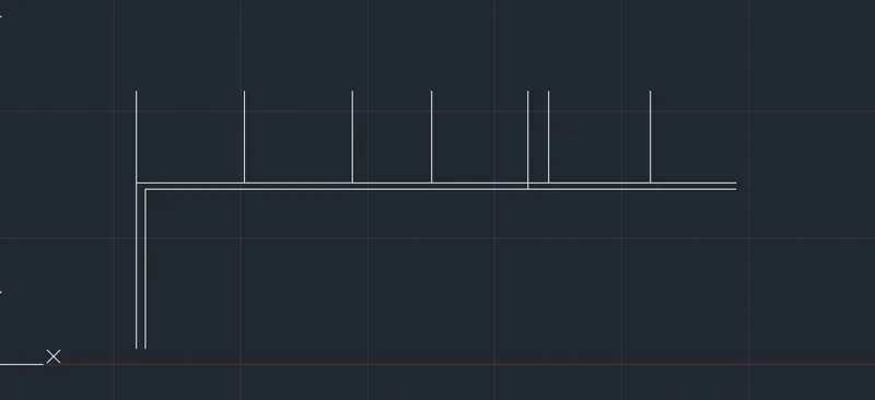
- Take offset 300 mm from horizontal line and 450 from vertical line. to draw tthe column
- now start taking offsets from vertical line.
- take offset 5315 from vertical line
- Again take offset 5320 from last offset.
- Again take offset 3900 from last offset.
- Again take offset 4720 from last offset.
- Again take offset 1020 from last offset.
- Again take offset 5025 from last offset.
- Now Draw the column in the drawing width 450mm
STEP-2
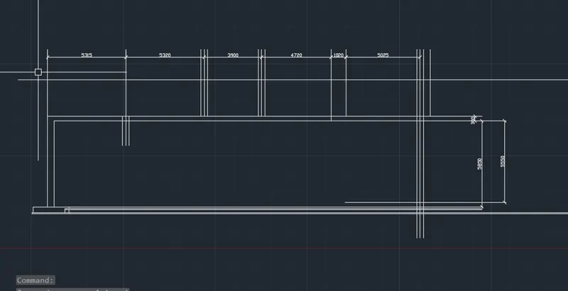
- Now draw the column off 450 mm for drawing the column take offset 225 from mid line to both side which every dimention is closed
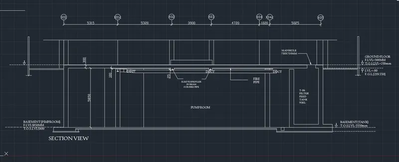
- draw the pcc layer of the drawing basement of the drawing fire pipe in the drawing
- and also draw the duct spacing
- Draw section of the column .
STEP-3
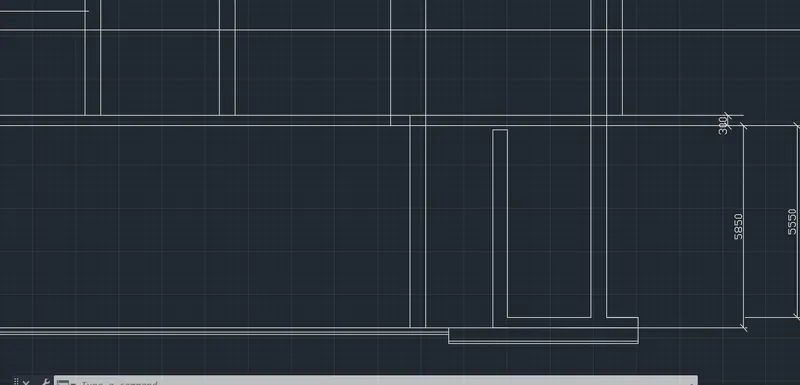
- Now we start drawing of section of the filter feed tank
- for this take line command and take offset 450 mm both side and bottom side. and in the base ment again take 450mm.
STEP-4
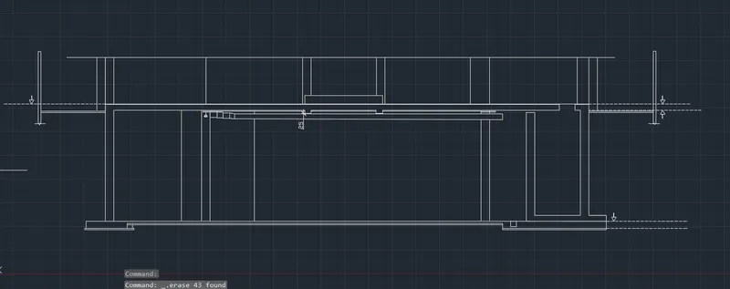
- Now we start drawing of the Ground floor TOS level its width 300mm and width the help of rectangle draw it.
- draw the basement tank and use diffrent line weight where required.
- Also draw the sleeve sprinkler in the bem fire pipe.
STEP-5
ANNOTATION:
- Now we we start the annotation in the drawing
- for this go to leader commmand an go to block type and put it in the corner of the dimention
- draw the diffrent annotation width the help of annotation tool bar .
- draw the leader X01 , X01c, X03, X04, X04c, X05
- GO TO LEADER AND PUT IT WHERE REQUIRED.
- Us the leader in the pump room.
- draw the duct space with the help of line and rectangle command.
STEP-6
HATCHING:
CREAT HATCHING
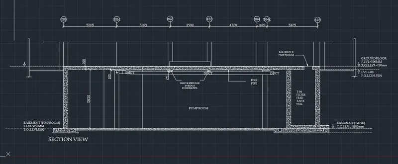
- Now we are starting hatching , hatching is the process of filling or showing the drawing with diffrent patterns and colors
- Go to commmand bar put hatch , select type predefine and for wall put AR-CONC pattern color gray .
- Pic-up the hatching and fillit on the walls portion
- Again Take hatching and select solid put it in the wall where required.
STEP-7
LAYOUT DRAWING-
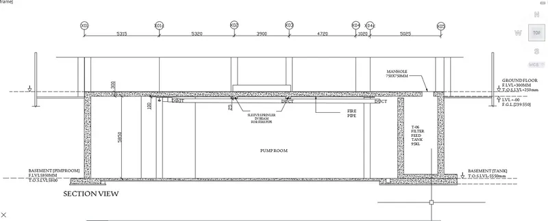
LAYOUT DRAWING
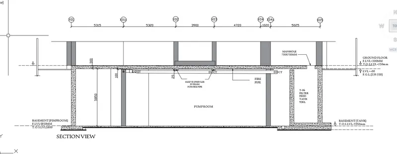
RESULT: GIVEN SECTION OF THE RESIDENTIAL BUILDING ARE COMPLETED WITH THE PROPER DIMENTION STYLE AFTER THIS WE USED THE ANNOTATIONS AND HATCHNG IN THIS DRAWING .AFTER MAKING THE DRAWING FINAL DRAWING SCREENSHOTS ARE ATTACHED WITH RESULTENT DRAWING .THE LINK OF THE DRAWING OF AUTOCAD IS ALSO ATTACHED FOR REFRENCE.
AUTOCAD DRAWING LINK
https://web.autocad.com/acad/me/sid/shares/drawings/2e595a75-bbb7-4237-ba92-225edacb5f3e/editor
https://web.autocad.com/acad/me/sid/shares/drawings/2e595a75-bbb7-4237-ba92-225edacb5f3e/editor
DRAWING: