Creating Kitchen layout, Hatching of Architectural elements and sectional view of an Industrial Building in AutoCad
QUESTION-1:
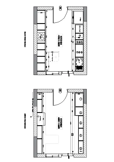
Create the layout of the Kitchen and provide Hatches pattern as shown.Also ,use blocks wherever required.Provide appropriate dimensions in the plan.Assume the size of doors,appliances and others as per the standards.
ANSWER:
AIM: To create a layout of kitchen and provide hach pattern as shown in challenge question.
INTRODUCTION:
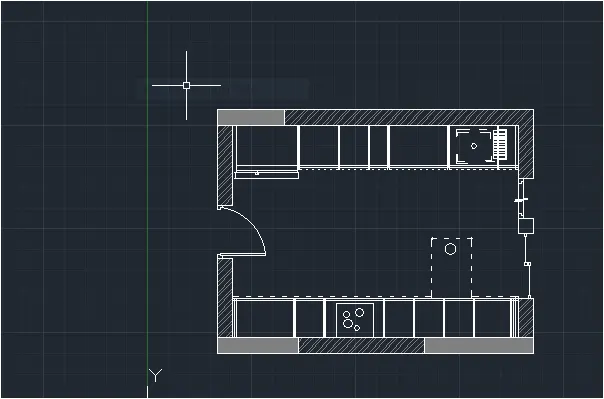
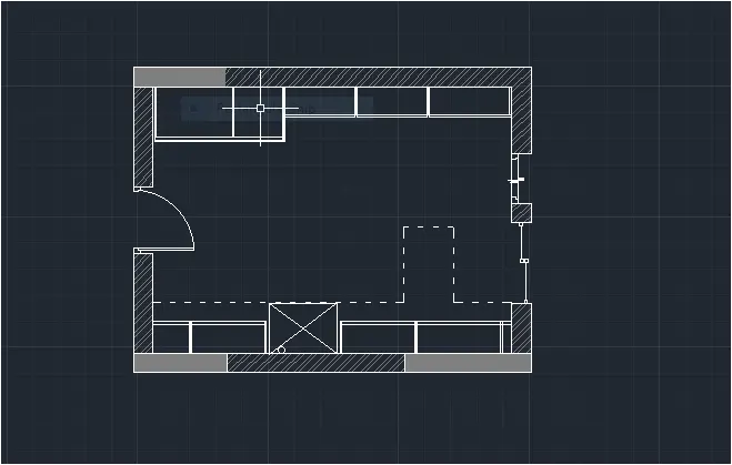
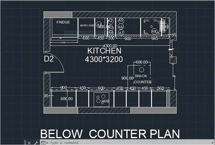
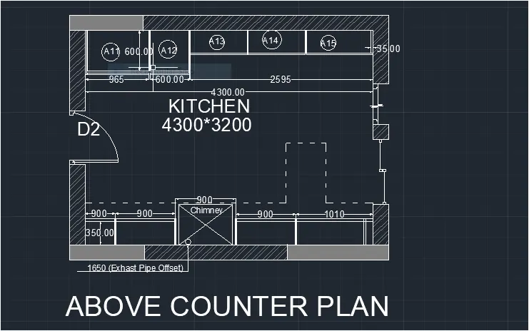
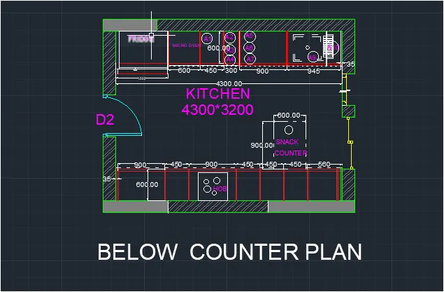
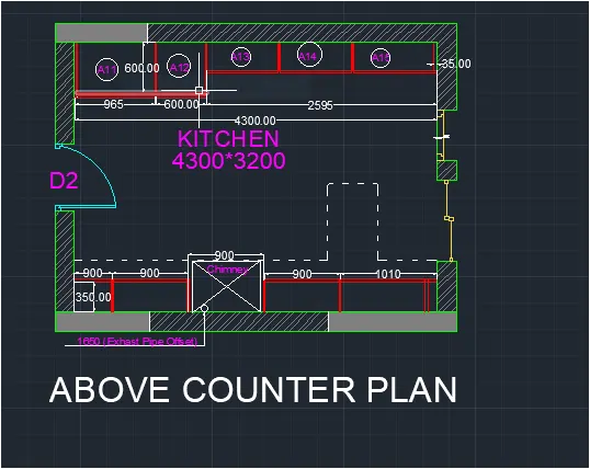
- TWO Kitchen plans are given one below counter plan and another above counter plan .
- Below contour plan consist of fridge,micro oven,cupboards,hob dishwashers etc.
- Above contour plan consists of cupboards, Chimneys etc.
- We used following commands to draw layout.
- Xline offset circle Extend ,Hach,array, Dimension,Trim Text etc.
PROCEDURE:
- OPEN AUTOCAD.
- In startup setting start from scrach select (Meter).
- Open grid and snap setting.
- Change grid and grid spacing t0 0.1
- Change major line every grid line to 10
- Turnoff adaptive grid.
- Type UN in command box and press enter.
- Change units type to decimal and precision to 0.00 and insertion scale to milimeter.
CREATING BELOW CONTOUR PLAN
STEP-1:
- Type rec or rectangle in the command tab or we can select dircetly from toolbar.
- Specify first corner point: Select any point on grid.
- Specify other corner point or[Area: dimension:rotation]:D
- Specify length for rectangle :Type 4300 and press enter.
- Specify width for rectangle :Type 3200 and press enter and set the dircetionas first quadrant
- Type o in toolbar and press enter or click offset from the modify toolbar.
- Specify offset distance : Type 230 and press enter.
- Select the object to offset : Select the rectnagle drawn earlier and select the outside of the rectangle.
- Explode the rectangle using explode command.
- Create a door opening using line and trim command.
- Type o or offset and press enter.
- Specify offset distncae : Type 600 and press enter.
- Select object to offset : Select the bottom edge of the inner rectangle and select on top.
- Type offset and press enter.
- Specify offset distnace: Type 40 press enter.
- Select object to offset : select the last offset line and click on bottom.
- Draw a line starting from left end of the last offset line and bottom left corner of the inner rectangle.
- Type offset and press enter.
- Specify offset distnace : Type 35 and press enter.
- select object to offset : Select the line drawn earlier and click on right.
- Type offset and press enter.
- Specify offset distnace: Type 900 and press enter.
- Select object to offset : Select the line drawn earlier and click on right side.
- Type offset and press enter.
- Specify offset distance : Type 450 and press enter.
- Slect object to offset : Select the last offset line and click on right.
- Slect object to offset : Select the last offset line and click on right.
- Slect object to offset : Select the last offset line and click on right.
- Type offset
- Specify offset distance : Type 630 and press enetr.
- Slect the object to offset : Select the last offset line and click on right.
- Type offset and press enter.
- Specify offset distnace : Type 10 and press enter.
- Select object to offset : Select the bottom edge of the inner rectnagle and select top .
- Type offset end pressenter.
- Specify offset distance : Type 20 and press enetr.
- Selcet object to offset: Select the line offset at 35 from left and click on right.
- Repeat the same process for all the offset lines drawn. above.
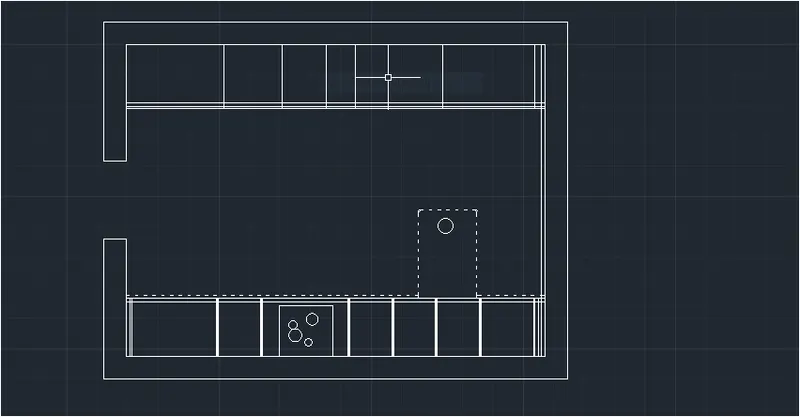
- Create hob using rectangle and circle command.
- Create the snack counter using line commnad and ISO dash space as line type with line type scale as 0.1 and fillet option at top corners.
STEP-2:
- Type offset and press enter.
- Specify offset distance: Type 600 and press enter.
- Select object to offset : Select the top edge of the inner rectangle and selet on bottom.
- Type offset press enter.
- Specify offset distnace : Type 1000 and press enter.
- Select object to offset: Select the doors side linet to make offset.
- Type offset press enter.
- Specify offset distance: Type 10 and press enter.
- Select object to offset : Select the top edge the inner rectangle and select on bottom.
- Draw aline starting from left end of the last offset line and bottom left corner of the inner rectangle.
- Type offset an press enter.
- Specify offset distnace :TYpe 35 and press enter.
- Select object to offset : Select the line drawn earlier and click on left.
- Type offset and press enter.
- Specify offset distnce: TYpe 300 press enter.
- Select object to offset: Select the last offset line and click on left.
- Type offset and press enter.
- Specify offset diatnce : Type 645 and press enter.
- Select object to offset : Select the last ooffset line and click on leftside.
- Type offset
- Specify offset distance : Type 900 and press enter.
- Select object to offset : Select the last offset line and click on left.
- Type offset.
- Specify offset distance: type 300 and press enter.
- Select object to offset : Select the last offset line and click on left.
- Type offset.
- Specify offset distance: type 450 and press enter.
- Select object to offset : Select the last offset line and click on left.
- Type offset.
- Specify offset distance: type 600 and press enter.
- Select object to offset : Select the last offset line and click on left.
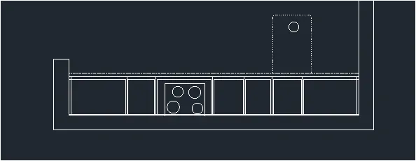
- Cretaing the fridge component using rectangle ,2 point circle and line command as shown in fig.
- Doos and Windows are created.
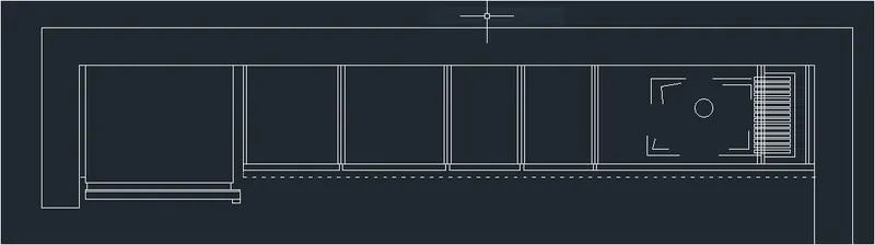
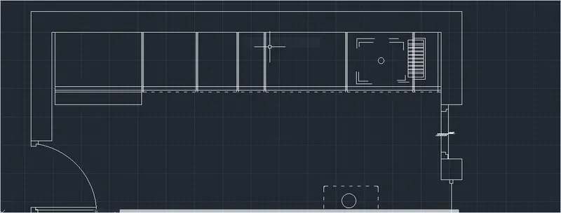
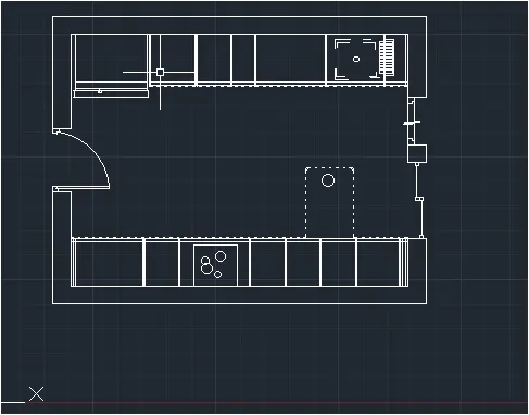
CREATING ABOVE COUNTER PLAN:
STEP-1:
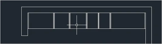
- Using copy command ,copy all the necessary components of below contour plan and paste at any point as walls and doors and window.
- Type offset and press enter.
- spaecify offset distnace : Type 300 and press enter.
- Select object to offset : Selct the line drawn earlier and click on right.
- Type offset and press enter.
- spaecify offset distnace : Type 450 and press enter.
- Select object to offset : Selct the last offset line and click on right.
- Type offset and press enter.
- spaecify offset distnace : Type 900 and press enter.
- Select object to offset : Select the last offset line and click on right.
- Select object to offset : Selct the last offset line and click on right.
- Select object to offset : Selct the last offset line and click on right.
- Type offset and press enetr.
- Specify offset distance : Type 1010 and press enetr.
- Select object to offset : Select the last offset line and click on left.
- Type offset and press enetr.
- Specify offset distance : Type 10
- Type offset and press enetr.
- Specify offset distance : Type 20 and press enetr.
- Select object to offset : Select the line offset at 35 from left and click on right.
- create the chimney in the 0.9 distnace gap using a rectangle command.
- Create the snack counter using line command and ISO dash as line type scale as 0.1
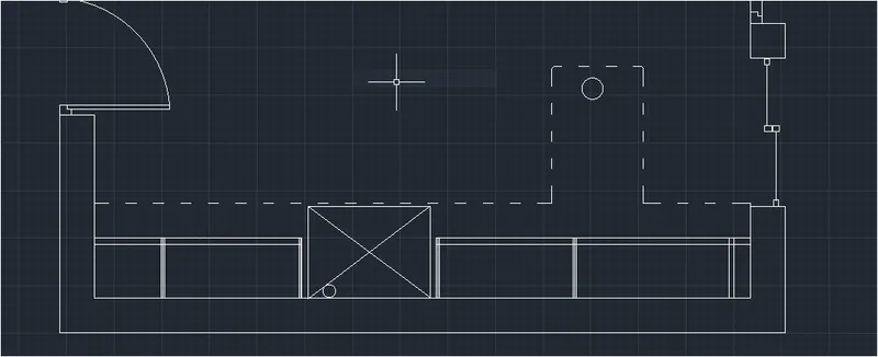
STEP-2:
- Type o or offset and press enter.
- Specify offset distnace : Type 600 and press enetr.
- Select object to offset: Select the top edge of inner rectangle and select on bottom.
- Type offset and press enetr.
- Specify offset distance : Type 350 and press enter.
- Select object to offset : Select the top edge of inner rectangle and select on bottom.
- Type offset and press enetr.
- Specify offset distance : Type 10 and press enter.
- Select object to offset : Select the top edge of inner rectangle and select on bottom.
- Draw a line starting from left end of the last offset line and bottom left corner of the inner rectangle.
- Type offset and press enetr.
- Specify offset distance : Type 35and press enter.
- Select object to offset : Select the line drawn earlier and click on right.
- Type offset and press enetr.
- Specify offset distance : Type 600 and press enter.
- Select object to offset : Select the last offset line and click on right.
- Draw a line starting from left end of last offset line and bottom left corner of the inner rectangle of 0.35 distance.
- Type offset and press enetr.
- Specify offset distnace : Type 865 and press enter.( for 3 times).
- Selct object to offset : Select the line drawn earlier and click on right.
- Doors and window are created .
- Trim of extra portions.
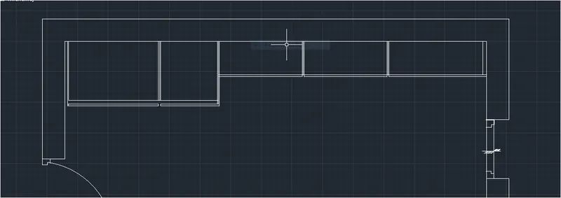
The results of step-1 after adding doors and windows is as folows.
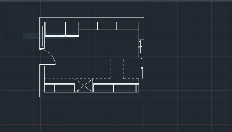
TO CREATE DOOR AND WINDOWS:
STEP-1:
DOOR-3
- Selct line command and select outer end of door opening.
- Draw a line of distnec 80 and keep the curser to the right and draw a line of 50
- Keep then curesr to down and draw a line of 60 and keep the curser to right and draw a line of of 50 and draw a line perpendicular to bottom end.
- Mirror the same created and paste it on other side of door end.
- Draw a line connecting the top edge of boot the shapes.
STEP-2:
DOOR-2:
- Selct the command and selct the outer end of the door opening.
- Draw a line of distance 0.08 and keep the curser to the right and draw a line of 50 and draw aline perpendicular to bottom end.
- Mirror the same created and paste other side of door.
- Type rec or rectnagle in the command box or select rectangle from the draw toolbar.
- Specify first corner point: Select any point on grid.
- Specify other corner point or [AREA,DIMENSION.ROTATION]:Click on dimensions.
- Specdify length for rectangle: Type 800 and press enter.
- Specify widt for rectangle : Type 60 and press enter and set the direction as first quadrant.
- Select start center end command from the drop down of arc tool from draw tool bar.
- Select the start point : Select right edge of the shape drawn.
- Select the centerpoint: Select the bottom of rectangle drawn.
- Select the end point : Select the bottom end of the shape drawn at the other door end.
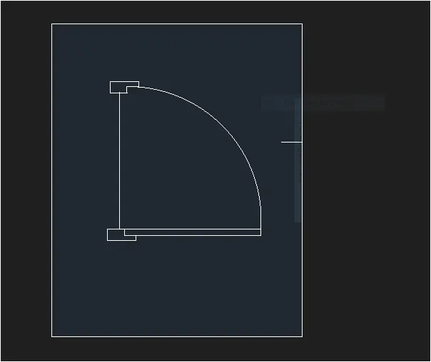
STEP-3:
WINDOW:
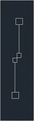
- Using rectangle command and draw 2 rectangles at the center of the window.
- Using line command draw 2 line from the midpoint of 2 rectangles to the opposite edges of window.
- At the point of intersection of these lines draw 2 rectangles on both edges as shown in figure.
STEP-4:
A-1:
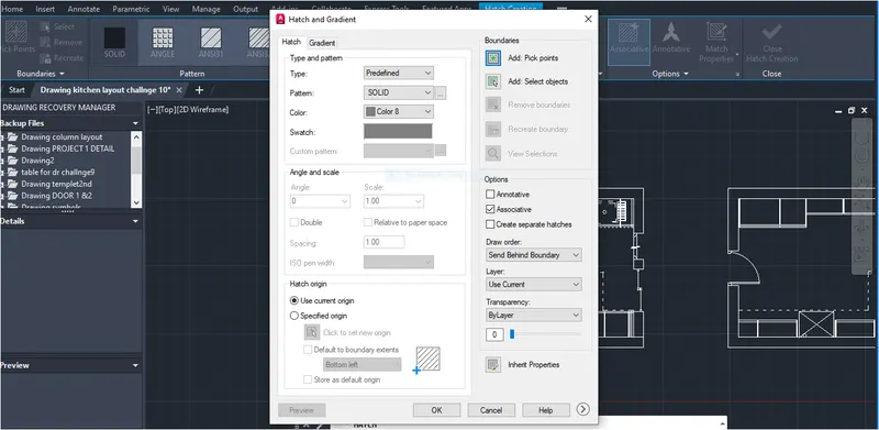
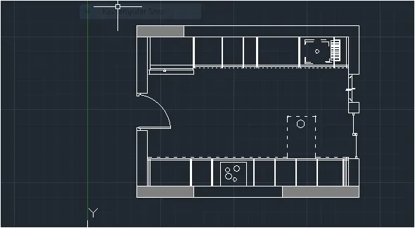
- Give the hatch to the island.
- press enter.
- Command: HATCH go to the hatch setting
- Click on predefined.
- Next select the hach pattern SOLID.
- Select colour of hach is 253.
- Next click on pick point.
A-2:
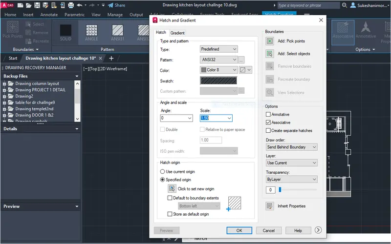
- Type hach in command box and press enter.
- Select the hach setting.
- And next select the type is predifined.
- Next select hach pattern as ANS132.
- Next select the colur of hach is COLOUR 253.
- Next click on pick point.
TEXT AND DIMENSIONS:
TEXT
- Set as layer as text.
- ST enetr for style text dialog box.
- Select the font name as AIRAL.
- and change the text height as 200
- Apply > set current>Close.
- MTEXT enetr multiline text .
- Specify the name of objects
- Edit the text as required size.
DIMENSION:
- Set layer as Dimension
- D enter for dimension style manager.
- Change extension line suppress check mark on ext line 1 nad ext line 2 from Lines tab.
- Change the arrowwheast first & second dot small from symbols and arrow tab.
- Text placement vertical & Horizonatl select centerd from text tab.
- Use over all scale of 30 from fit tab .
CREATING LAYERS:
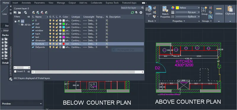
- Open layer properties and crete new layers by clicking on new layer or right click on any layer and select new layer to create new layer.
CREATING BLOCK TO COMPONENTS:
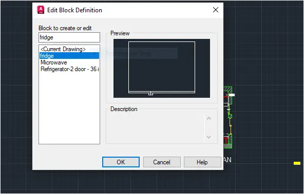
- Type 'B' to block components in the drawing Select Was basin and enter block and select Fridge and enter 'B' to block the particular element.
FOR LAYOUT CREATION IN AUTOCAD;
STEP-1:
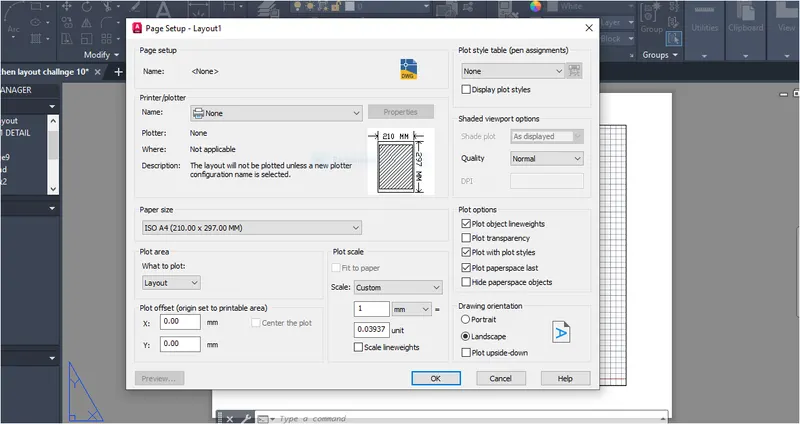
- From the floor plan drawing click left click of layout tab.
- Select Page Setup Manager.
- Choose paper size as A4.
- Then click ok.
STEP-2:
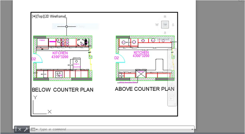
- In the command prompt write layout.
- Select the new and choose suitable name.
- From the layout area Command MVIEW.
- Select the plot area and paste the object.
STEP-3:
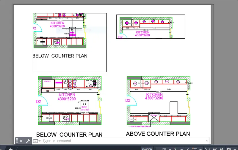
- In the plot area Type Msview.
- Select the area and paste another object to show.
- Use Ms and ps command for editinn and zooming the object inside plot area.
RESULT:
QUESTION-2:
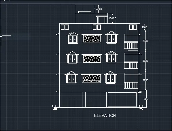
Create the elevation of the plan created in the challnge 7 and apply proper hatch in the walls and doors windows and other architectural elements.Refer to the dimensions in plans and sections in challenges 7.
ANSWER:
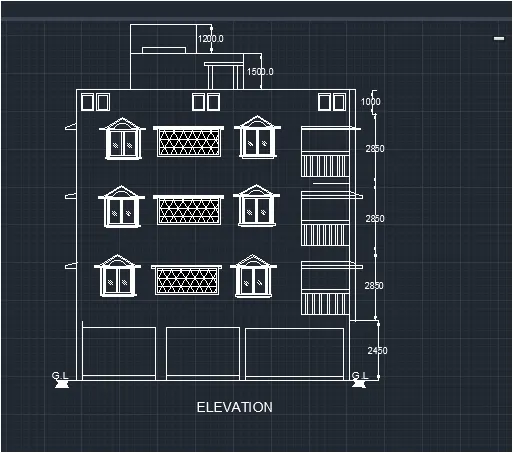
AIM : To cretae elevtion of the plan created in challenge7.
INTRODUCTION:
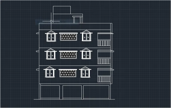
- Create elevation of the plan created in challenge 7 and apply hatch to wllas and doors windows and other architectural elements.
- XLINE: It menas construction line.it has infinty edges we used for making wall.By typing xl on command line we envoke this tool.
- LINE: It connects one point to another points.used to draft various elements.
- TRIM: This modification tool helps to cut extended egdes on the drawing.and to trim inbetween two line or elementsTR command to envoke this tool.
- EXTEND: It is also a modification tool if we have some broken edges or need to extend some portion towards another element.'EX' command to envoke the tool.
- Offset: Offset the existing element with certain distance this tool avoid to cretae new parallel.
- Layres: Each and every elements has unique property and unique style This layer tool helps to organize those .Line weight line style colour gradientd ,freeze lock, it has numerous benefits in autocad drafting.
- HATCH: Haching helps to fill the voids with certain texture on it.if we draft wall means we mention the brickwork detaisl with hwlp of hatching.
- CIRCLE: Used to make circle elemets in the sheet .Type 'c' to enoke this tool .hEre it is used to draft door.
PROCEDURE:
- OPEN AUTOCAD.
- In startup setting start from scrach select (metric).
- Open grid and snap setting.
- Change grid and grid spacing to 0.1
- Change major line every grid line to 10
- TURNOFF adaptive grid.
- Type un in command box and press enetr.
- Change units type to deimal and precision to 0.00 insertion scale to milimeter.
STEP-1:
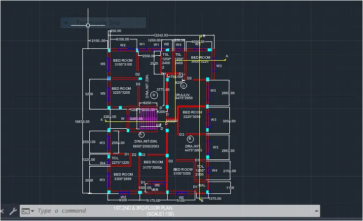
- OPEN EXISTING PLAN CREATED IN CHALLENGE-7.
STEP-2:
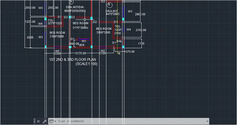
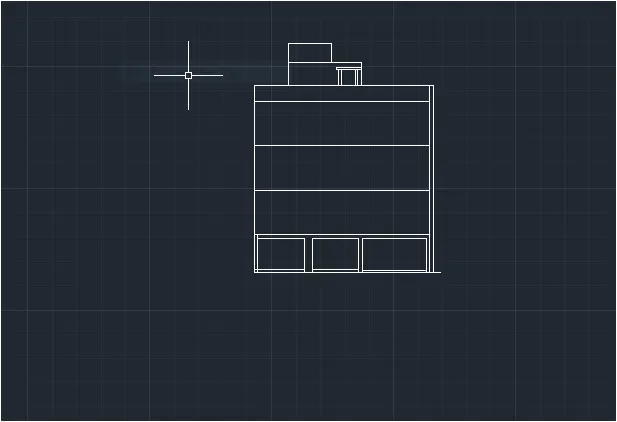
DRAW CONSTRUCTION LINES.
- Specify command : XL in command tab.
- Select xl: Vertical.
STEP-3:
CREATE A WINDOW
- Take projection from previous plan lines.
- Use line command to draw lines in window.
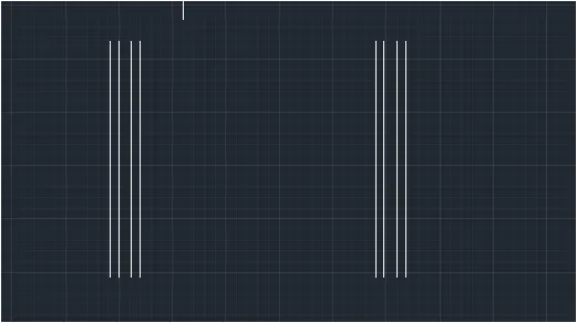
- Create bottom lines and using line and offset command.
- Use rectangle command for glass portion.
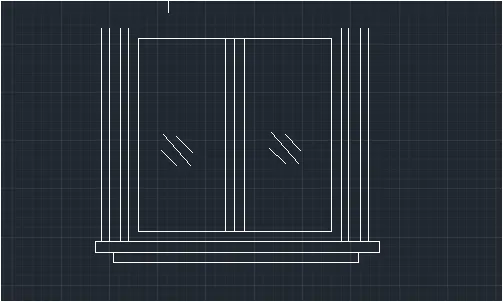
- Use arc command to draw top arc.
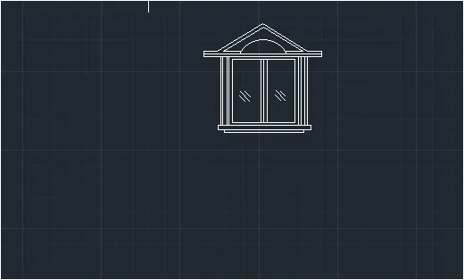
CRETED BLOCK OF WINDOW.
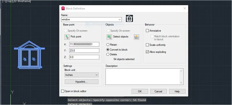
- Command: REC
- Select the start point.
- Click on DIMENSION.
- length: 24
- Width: 10
- Press enetr.
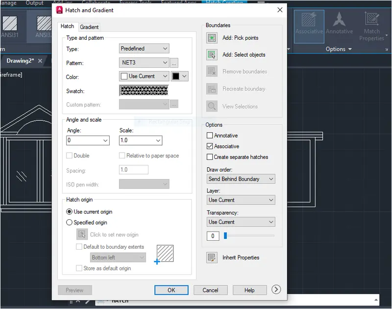
- Command : H ( for hatch)
- Select the predefined type.
- Select the hatch pattern as shown below.
- Select the pick point
- Also select the base point and give the hatch.
- Press enter.
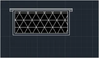
CRETED BLOCK OF OBJECT
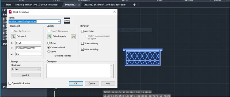
- Provided for creted window .
- Use copy command and select the array .
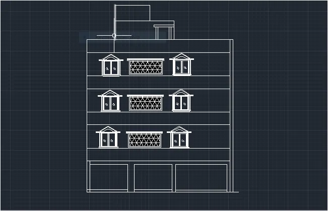
- Provided for grill and chajja projection
TEXT AND DIMENSION:
TEXT
- Set as layer as text.
- ST enetr for style text dialog box.
- Select the font name as AIRAL.
- and change the text height as 200
- Apply > set current>Close.
- MTEXT enetr multiline text .
- Specify the name of objects
- Edit the text as required size.
DIMENSION:
- Set layer as Dimension
- D enter for dimension style manager.
- Change extension line suppress check mark on ext line 1 nad ext line 2 from Lines tab.
- Change the arrowwheast first & second dot small from symbols and arrow tab.
- Text placement vertical & Horizonatl select centerd from text tab.
- Use over all scale of 30 from fit tab .
STEP-3:
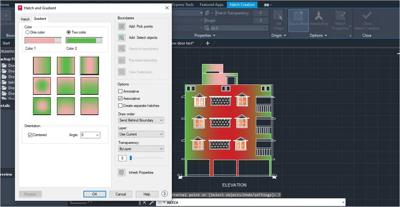
- Comand : H( for hach)
- Click on setting in command section
- Click on grident.
- Select the pattern
- AS shown below.
- Select the PICK UP POINT.
- Also select the base point.
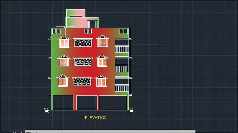
- Hatch the object and press enter.
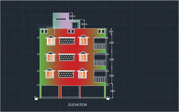
RESULT:
QUESTION-3:
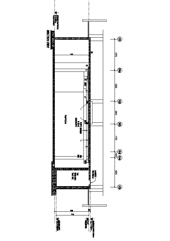
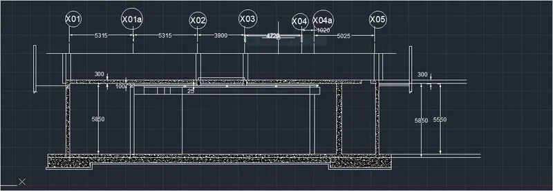
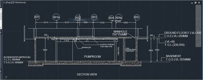
Create the section view of an industrial building as shown in fig .Provide appropriate and dimensions wherevr required.Also provide annotations to the drawing.
ANSWER:
AIM: To create section for given dimension by using drafting and modify command.
INTRODUCTION:
- Using various commands in AUTOCAD draft the given industrial building.
PROCEDURE:
- Click on AUTOCAD application.
- Type qnew in command section.
- Click on advance setup.
- Units decimal precision 0.
- Angle precision 0.
- Angle measure: EAST.
- Set angle direction counter clockwise press enter.
- Press next.
- SET the area LENGTH-100 &WIDTH-100 and press ok.
- In command box press UN ( for units)
- Give the units in decimal and milimeters press enter.
- Command: Z(for zoom)
- Type a in command section and press enter.
STEP-1:
- Type rec or rectangle in command box.
- Specify the start point.
- Click on the Dimension: length-25300 and width-5850 and press enter.
- Command : offset
- Give the offset distance 300 and press enter.
- Command: explode
- Select the object and press enter.
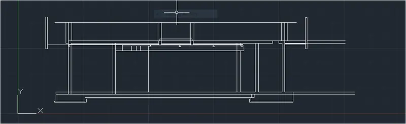
- Command: Line by using line command draw the remenning part. and press enter.
STEP-2:
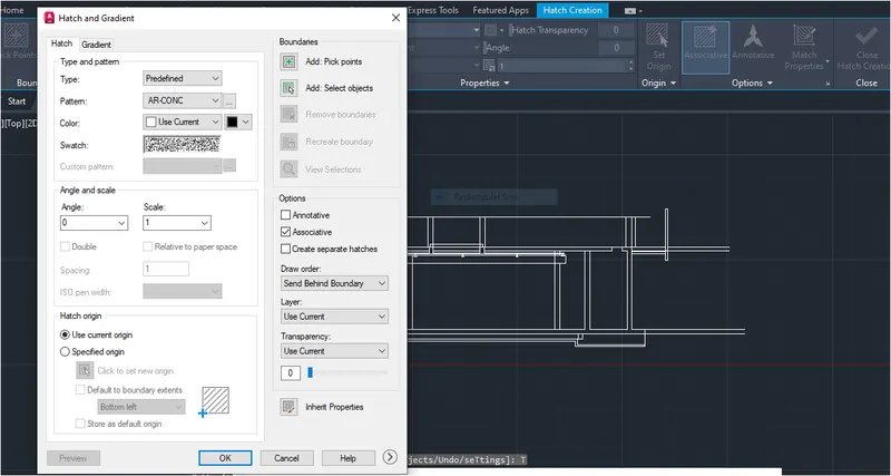
- Command: H( for hach).
- Click on seating in command section.
- Select the pattern as shown in below.
- Select the pick point.
- Press enter.
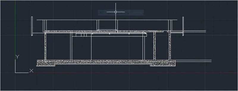
- Go to the object and give the hatch.
- After that press enter.
STEP-3: DIMENSION
- Command: Dimlin( for dimension).
- Give the dimension
- Command : DIMCONTINUE.
- And give the all dimension and press enter.
STEP-4: TEXT
- Command : Mtext ( for text).
- Write the text over section plan press enter.
- Then go to the ANOTATION tab.
- Click on Multileder.
- Click on content.
- Select the MTEXT option.
- Select 2 point for leder.
RESULT:
- Created the section view of an industrial building as given in fig and also provided appropriate hatches dimensions and annotations by using AUTOCAD.
CREATING LAYOUT:
STEP-1:
- From the floor plan drawing click left click of layout tab.
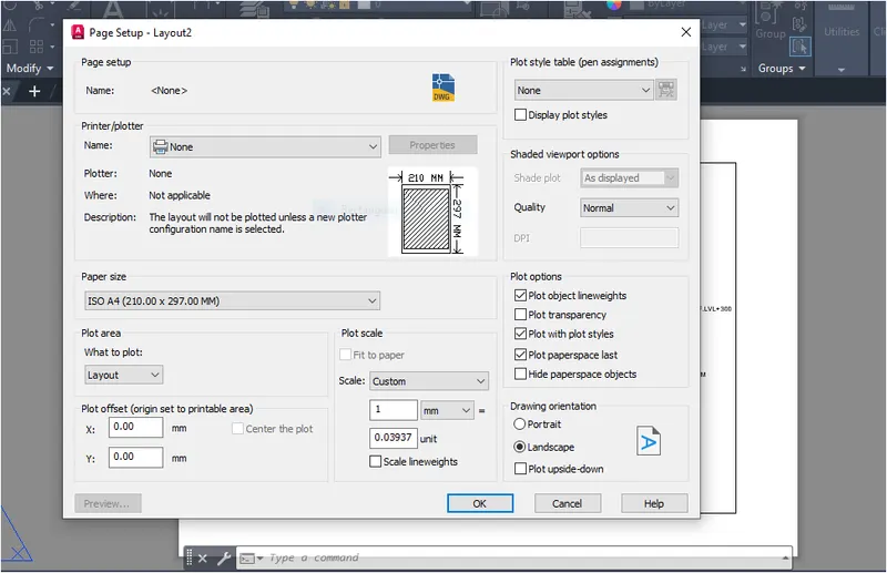
- Select page setup Manager.
- Choose paper size as A4
- Thenclick ok.
- In the command prompt write layout .
- Select new and choose suitable name.
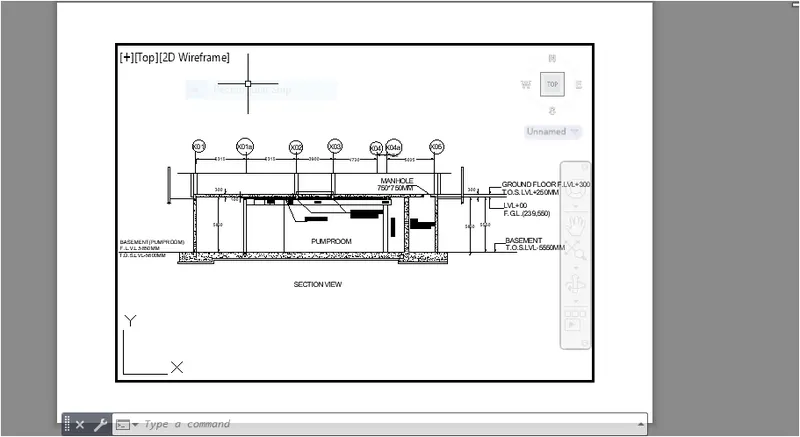
- From the layout area command MVIEW.
- Select the plot area and paste the object.
STEP-2:
- IN the plot area type MSVIEW
- Select the area and paste the other objects to show.
- Use MS and ps commands for editting and zooming the objaect inside plot area .
- Then click enter and complete the layout.
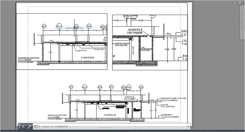
FINAL RESULT: