Creating Kitchen layout, Hatching of Architectural elements and sectional view of an Industrial Building in AutoCad
AIM :-Creating Kitchen layout, Hatching of Architectural elements and sectional view of an Industrial Building in AutoCad
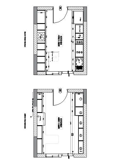
PROBLEM 1 :Create the layouts of the Kitchen and provide hatches pattern as shown. Also, use blocks wherever required. Provide appropriate dimensions in the plan. Assume the size of doors, appliances and others as per the standards.
STEP WISE PROCEDURE:-
- Click on AutoCAD application
- Open a new drawing
- Keep ortho, Object snap >ON
- Keep Snap and Grid > Off
- Un+enter
- Type > Decimal, Precision > 0
- Units to scale inserted content > milimeter
- Enter
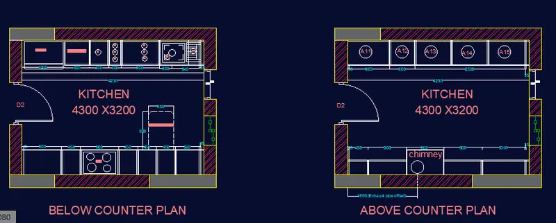
- Below Counter Plan :
- Take xline command
- Put xline horizontal and xline vertical
- Trim the negative coordinates
- Take offset of both lines at 230mm distance
- Take offset command
- Select distance as 4230 and select object as vertical inner wall line
- Again take offset command
- Offset the last object at a distance of 230
- Trim the unwanted lines
- Take offset command
- offset distance > 3200
- Select object > Click on Horizontal line
- Again take the offset to last object at 230

- Trim the unwanted lines
- From Properties tab
- Click on drop down
- Other > Load
- Select ACAD_ISO02W100 > OK
- Set Global Scale Factor as 10
- Provide the dotted line at 600 distance as shown below
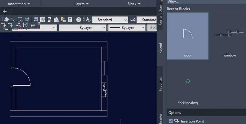
- Assume the door size as 1000x 2100mm
- size of window = 700x1350mm
- make the figure and save it as block
- insert it in proper positions as shown in figurebelow.
- Take offset command
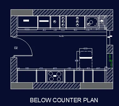
- Offset the Short vertical wall at a distance of 35, 935, 1385, 2285, 2735, 3185, 3635, 4195 as shown below
- Assume the thickness as 20
- Take offset command and provide the thickness as given below
- Use the line command in Hob section
- Use the circle command in hob
- Take line command
- Provide the snack counter using dotted line as shown below
- Now to create offsets for fridge, microwave and all
- Offset the Short vertical wall at a distance of 1000, 1600, 2050, 2350, 3250, 4195 as shown below
- Take a dotted line
- Provide it at a height of 600 from upper horizontal line
- Trim the projection lines
- Assume the thickness as 12
- Type H and enter
- Select ANSI32 hatching
- Select the area where to provide that hatch
- Enter
- Take properties of hatching system
- Take scale of hatch pattern as 400
- From the draw panel
- Click on hatch
- Select Solid hatching
- Select gray color
- Select the area where to provide that hatch
- Click it.
- Click on Annotation
- CLICK on single line text
- select the point
- take height of text as 200
- wright all the text
- for head line as BELOW COUNTER PLAN T the text height is 600
RESULT:-
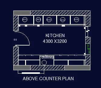
Above Counter Plan
- Copy the Below counter plan
- Trim all the lines inside in the room
-
- Provide the offset at 350mm
- Assume the door size as 1000
- Leave the space for door as shown below
- Take offset command
- Offset the Short vertical wall at a distance of 35, 965, shown below
- Assume the thickness as 12
- Take offset command and provide the thickness as given below
- Use the circle command in chimney to show the exhaust pipe
- Assume the size of Window as 800 and door near that window size is 800
- From the draw panel
- Click on hatch
- Select ANSI32 hatching
- Select the area where to provide that hatch
- Enter
- Take properties of hatching system
- Take scale as 300
- From the draw panel
- Click on hatch
- Select Solid hatching
- Select the area where to provide that hatch
- Enter
- CLICK on single line text
- select the point
- take height of text as 200
- wright all the text
- for head line as ABOVE COUNTER PLAN T the text height is 600
RESULT:-
- cliclk on the layerproperties
- give the names of the layers with the colors
- the figure shows below
- give the colours of hatching also
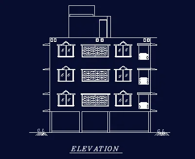
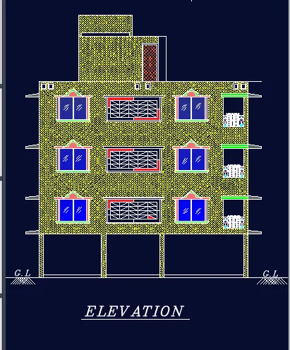
PROBLEM NO 2:-Create the elevation of the plan created in the Challenges 7 and apply proper hatch in the walls, doors, windows, and other architectural elements. Refer to the dimensions in Plans and sections in Challenges 7.
Refer to the elevation that needed to be created.
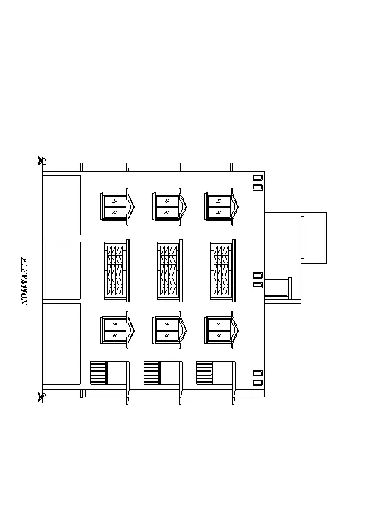
STEPWISE PROCEDURE:-
- Click on AutoCAD application
- Open a new drawing
- Keep ortho, Object snap >ON
- Keep Snap and Grid > Off
- Un+enter
- Type > Decimal, Precision > 0
- Units to scale inserted content > milimeter
- Enter
- To draw the elevation, the Plan of challenge 7 is reffered
- Take the xline command
- Select > Vertical
- Specify the points required to take projection for Elevation
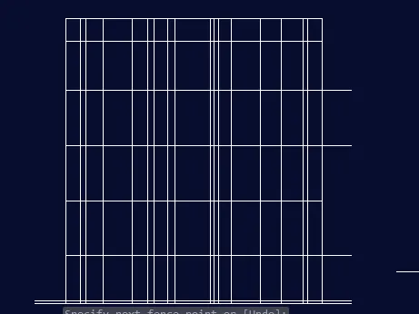
- Take the perpendicular line
- Enter
- Take the offset command and provide it at required places
- Use the line command to show the handgrills for balconr
- Use the line command to show the chajjas
- Use rectangle command to show the design to the parapet
- To create the hatching
- From draw panel, click on > Hatch
- Select the hatch type
- Scele it
- And provide it at required places
- To provide the hatching to windows and ventilators, I used the gradient style, which shows the following results
- type H enter
- select hatch pattern and appropriate scale with the color that have
- take them in required place .
RESULT:-
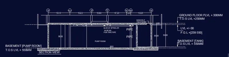
PROBLEM NO 3:-
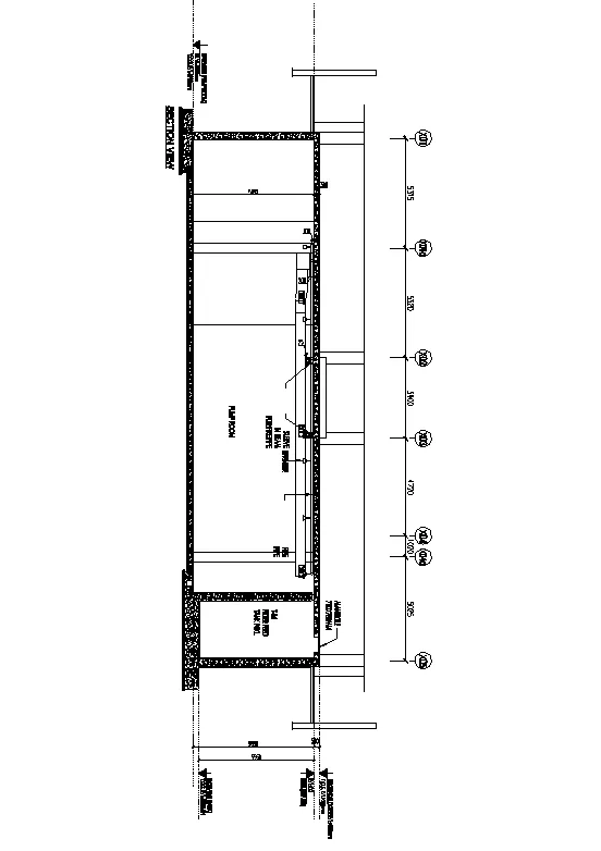
Create the section view of an industrial building as shown in Figure. Provide appropriate hatches and dimensions wherever required. Also, provide annotations to the drawing.
STEPWISE PROCEDURE:
- Click on AutoCAD application and open this application
- Type QNEW in command bar and enter
- Select default setting as Metric
- In default setting click on use a wizard and in that advance setting and set unit as decimal and precision as 0 and press Next
- Set Angle as Decimal Degree and precision as 0 and click next
- Set Angle Measure as EAST and press NEXT
- Set Angle Direction as Counter-Clockwise and press NEXT
- Set Area by providing Length as 100 and Width as 100
- Press finish
- Keep ortho, Object snap >ON
- Keep Snap and Grid > Off
- Un+enter
- Type > Decimal, Precision > 0
- Units to scale inserted content > milimeter
- Enter
- Take a line command
- Specify first point > anywhere in the drawing
- Specify next point as > 30000 approximately > enter by keeping the curser to the right side
- Specify next point as > 5550 approximately > enter by keeping the curser to the up side
- Specify next point as > 30000 approximately > enter by keeping the curser to the left side
- Specify next point as > 5550 approximately > enter by keeping the curser to the down side
- Use the line command and offset command to show the components which are shown in drawing
- Similarlly draw the complete figure by use of line offset trim command
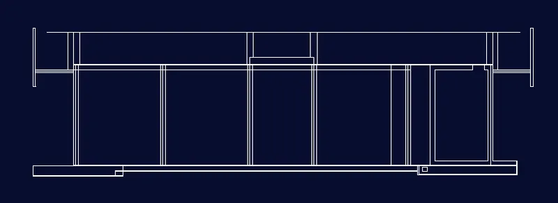
- To create the text
- click on the single line text
- height of text as 400mm
- write all the text in required place.
- type H enter
- select AC-CON
- select scale and click on the place where have to give the hatch.
RESULT:-