Creating Kitchen layout, Hatching of Architectural elements and sectional view of an Industrial Building in AutoCad
1. Kitchen Layout
Aim
To create the layouts of the Kitchen and provide hatches pattern
Introduction
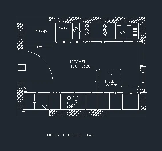
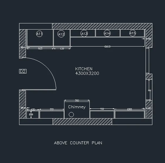
To create the layouts of the Kitchen and provide hatches pattern as shown. Also, use blocks wherever required. Provide appropriate dimensions in the plan.
First drawing the below counter plan and then the above counter plan
Procedure
Units are changed to mm
Units are given as Decimal and precision is set to 0.0.
Draw a rectangle of 4300 and 3200mm
Draw offset 230mm as wall thickness towards outside.
Fridge is drawn on leftmost side by rectangle tool.
Take an offset of 1000mm and start drawing slab showing cabinet below
Offset 600mm for cabinet below for microwave oven ,give an offset of 20mm to show the partition of cabinet below.
For width of cabinet give 600mm offset , give 20mm inside offset and 10mm offset for thickness.
From 600mm offset of microwave cabinet ,give an offset of 450mm for A1.
From that give 300mm offset A2,A3 ,A4 .
From 300mm offset give another offset of 900mm for A5,A6,A7.
Draw 35mm offset from the right side for the hinge and give thickness of 20mm.
From the 35mm draw an offfset of 300mm towards left for the cabinet below sink drain and rest will be cabinet below sink. (assumed 300mm from right).
For all the divisions of cabinet ,take 20mm on both side to show the thickness.
To create doors, extend the line of all the divisions and give 10mm offset on both sides in the 10mm offset given for thickness.
Erase the extended line and trim the horizontal line for opening of doors.
Create door on the left wall of the kitchen on both the plan.
Consider door of 900mm width. Trim 900mm from the wall thickness.
Draw a hinge of 20mm , and draw circle from centre of one hinge to another
Draw vertical line from one hinge to the circle to show the opening .
Trim off the rest of circle.
To draw the window,consider window of width 900mm .
From the 600mm width of cabinet ,take an offset of 900mm ( in line with the snack counter).
Draw the hinges and shutters of windows by using line tool.
To draw sliding doors take 200mm offset from the window.
Give an opening of 900mm take offset of 900mm from the 200mm offset.
Draw the shutters of the sliding door.
Copy it in the other plan also.
Dimension all the objects by dimension tool in the toolbar.
For text , select multiline text size -75mm style romans.shx .Command "ST".
Write all the text in respective places like fridge, hob, cabinet number etc
It is then hatched using HATCH command.
Solid hatch and ANSI 32 are the hatches provided.
Result
The given kitchen layout is drawn and hatches are provided
2. Elevation
Aim
To create the elevation of the plan created in the Challenges 7
Introduction
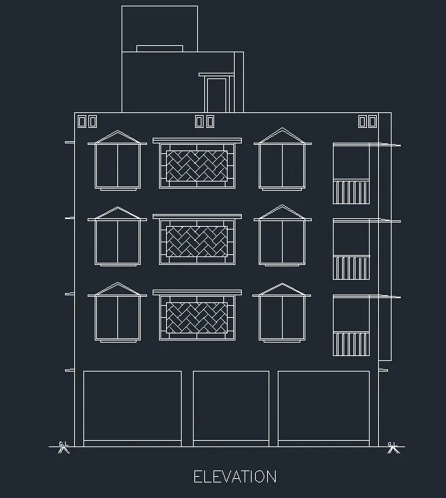
To create the elevation of the plan created in the Challenges 7 and apply proper hatch in the walls, doors, windows, and other architectural elements.
Procedure
Draw the horizontal and vertical line of dimension 10000 and 11000
Projections for the elevation from the plan and section is given using XLINE command.
Therefore the doors, windows and parking space are created as per the dimensions.
The rest of the lines are trimmed off using TRIM.
The window designs are then done using ARC,PLINE, LINE, OFFSET and HATCH command.
The AR-HBONE hatch is provided.
The design is then copied and pasted on the rest of the windows using COPY command.
The balcony is done using LINE, OFFSET and TRIM commands.
It is also copied and pasted to all the floors using COPY.
The overhead tank is then created using LINE command.
Using DTEXT command the text is provided.
Result
Thus the given elevation is drawn and hatch are provided
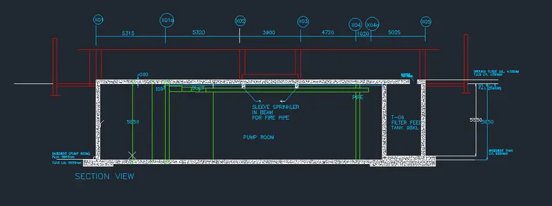
3. Section View
Aim
To create the section view of an industrial building
Introduction
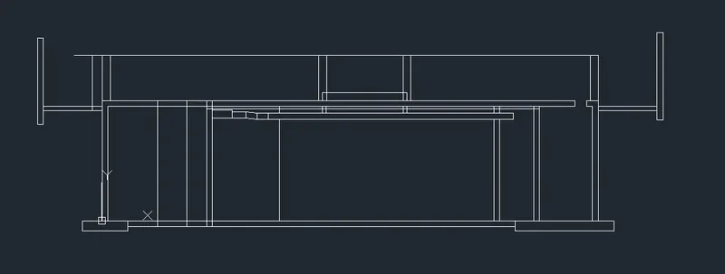
To create the section view of an industrial building as shown in Figure.
Provide appropriate hatches and dimensions wherever required.
Procedure
XLINE command is used to drawn construction lines.
OFFSET command is used to get the outline of the drawing.
The rest of the lines are trimmed off using TRIM.
Then LINE command is used to complete the outline of the drawing.
 \
\
The drawing is dimensioned using DIMLINEAR and DIMCONTINUE commands.
The dimension style is edited using DIMSTYLE command.
The text is provided using MTEXT and DTEXT commands wherever required.
The size of the text is changed from properties.
The linetype is also changed from properties by selecting the required line.
HATCH command is used to provide the hatch.
The componets of the drawing are then added to the respective layers usinng Layer properties manager in the Layer panel.
Result
The section view of an industrial building is created as given. Appropriate hatches and
dimensions wherever required are provided.