Creating Kitchen layout, Hatching of Architectural elements and sectional view of an Industrial Building in AutoCad
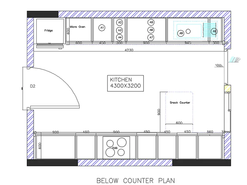
1) Creating the layouts of the Kitchen and providing hatches pattern as per the layout shown and inserting Blocks wherever required, with proper dimensions as per the standard.
:- First of all take the sheet in metric and set the units in Decimal with precession 00.
:- Now Creat a rectangle of 4300mm X 3200 mm.
:- Now Explode the rectangle with Explode Command.
:- Again take offset from these lines for Walls and with "Fillet" command fillet these inner lines and nbow wall is created.
:- Again with Line command draw a line and take offset at 1000 mm for Kitchen Door. and trim the lines here.
:- Now take rectangle command and creat A rectangle of size 50mm X 75 mm for Door Frame and with line command draw a line of 1000 mm from centre of this rectangle.
:- Take " Mirror" command and create mirror of this rectangle.
:- now draw a line for door at 12 mm and again take a line from this line at 25 mm for Door Panel.
:- Take " Circle" Command and creat circle with center point at door pannel point.
:- Take " Trim" Command and trim the extra circle and base line.
:- With " Block command convert this door into Block of Size 1000 mm.
:- Now " Insert' command will insert this door in the door position.
:- Also with "Line" and "Trim" Command window and balcony poertion in the wall.
:- Now take " offset" command and take offset from 4230 mm lines at both side of wall at distances of 600 mm.
:- Now Draw a rectangle of size 700x600 at one corner left side of Door and creat fridge with line, offset and trim command.
:- Now from fridge position at offset of 50 mm draw a line vertical meeting the wall and line at the end of line at 600 mm.
:- Again with offset command take offset from above line for Micro oven, A1, A2,A3,A4, A5, A6,A7, A9, A10 at distances of 600mm, 450mm, 300mm, 900 mm, 945 mm, 300mm, respectively. and creat a rectangle at the last for plateform frame of 35 mm width.
: Now take offset from wall at 350 mm and trim the extra lines to make boxes like the layout. alos to show panels take offsets at 25 mm for all panels.
:- Similarly, creat partitions on other side for hob and other acceseries. first take offset at 35 mm and then at 900mm, 450 mm, 900 mm, 450mm, 450mm, 450mm, 560mm, and 35 mm. and with offset and trim command creat separate places for each acceseries.
:- Now creat Circles to show the HOB as shown in the layout.
:- Also with Line command creat lins for Snacks Counter of 900 mm and 600mm sizes and show them in Dash lines and Show the dimensions.
:- Also Creat a window block a show in the figure with rectangle and line command and convert it into Block.
:- Now As shown in the figure, put Hatches inside the wall section with "hatch" Command. Separate hatches "Solid" and "AR-b816" inserted inside the wall section with option as " Creat separate hatches" option in the hatch setting option.
:- Now pu the door frame for the balcony door and draw lines meeting the walls.
:- Now Show the dimensions for the Door, Fridge, Micro oven, Snacks Counter, and other parts of the plateforms.
:- Thus , we created Below counter plan for the Kitchen.
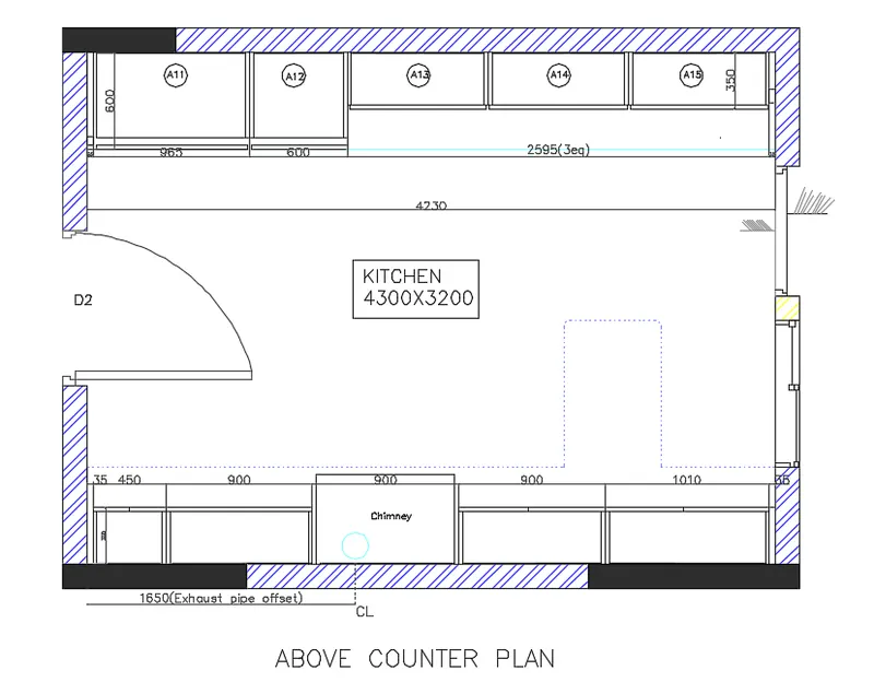
Similarly for Kichen layout Above the counter Plan is created.
:- Forst of al, copy the Kitchen Below counter Plan. and trim the lines which are not required like Fridges, and all plateform works.
:- Now draw a line at 35 mm offset from wall of 600 mm length
:- Again with offset command take offset from above line for A11, A12,A13,A14, A15 at distances of 965 mm, 600mm, 2595mm( Divide into 3 equal parts), respectively and creat a rectangle at the last for plateform frame of 35 mm width.
:- Similarly, creat partitions on other side for Cimney and other acceseries. first take offset at 35 mm and then at 450mm, 900 mm, 900 mm, 900mm, 1010mm, and 35 mm. and with offset and trim command creat separate places for each acceseries.
:- also Show the dimensions of each parts.
:- With DT/MT command write the text wherever required and at the center of the Layout for Kichen Size.
:- Also with Line command creat lins for Snacks Counter of 900 mm and 600mm sizes and show them in Dash lines and Show the dimensions for hidden portion.
:- Now As shown in the figure, put Hatches inside the wall section with "hatch" Command. Separate hatches "Solid" and "AR-b816" inserted inside the wall section with option as " Creat separate hatches" option in the hatch setting option.
:- Now put the door frame for the balcony door and draw lines meeting the walls.
:- Now Show the dimensions for the each parts.
:- Thus we have created the Kitchen Layout for Above Counter Plan.
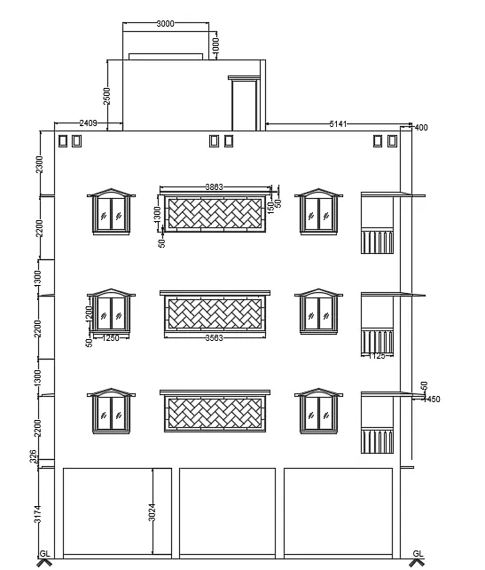
2.0 Creating the elevation of the plan created in the Challenges 7 and applying proper hatches in the walls, doors, windows, and other architectural elements Required.
:- First of all Copy the Elevation section of the building Created in the Challange-7.
:- Now With "Xline" horizontal and Vertical commands draw section lines with reference to the Elevation section for each floor, room, window, door, balcony, water tank etc.
:- with trim command trim the extra lines extending outside the elevation.
:- againg with offset command take offset from window rectangle at 50 mm inside the rectangle and at center draw line to divide it into two panel.
:- Now with line command show glazzing sign for glass in the mid window panel.
:- again from outer most rectangle take offset at 25 mm and 50mm, and 100 mm, for window frame and.
:- Now take offset in bottom at 50mm, 25mm, 75mm, for windoe bottom.
:- also, take offset on top of window for Lintel, at 75mm, and at 300mm for triangle shape of window roof.
:- now again, at center of line draw a vertical line and from top of this vertical line draw lines to meet lintel of the window. and trim the extra lines.
:- Again, with "3 point" arch command draw an arch over the window, below the triangle.
:- Now with fillet, Trim and offset command make the outer edges of the window.
:- Take block command and convert it into a Block named Window elevation.
:- Again with "Insert command Insert the window at all places of window.
:- Thus we have created the window.
:- Again for the central balcony,, atke offset at 100 mm for brick wall. again from outer most rectangle tae offset at 50 mm.
:- Now take offset on top of window at 100 mm, and 150mm, for window chajja and extend it 150mm beyod the window.
:- Now with trim command trim the extra lines available.
:- Now with " Hatch" Command put hatch inside the wall for Bricks and at centeral opening a separate hatch is provided.
:- Now dimensions are shown with Dimlinear command.
:- Again take Block Command and creat block for this balcony window.
:- Now with " Insert' command insert this balcony window at all the floor.
:- Thus, we have created the balcony window.
:- Agin for balcony, take offset at 900 mm from bottom line and again at 75 mm from thisline.
:- Now Divide, this line into 06 equal parts and with line command draw a line at ofset of 75 mm from one side.
:- Now take offset of 50mm, and create hand rain. thus all the hand rails are created.trim the extra lines.
:- Now with offset take offset above it at 50mm and 150 mm for chajja, and project it to outer wall and join to chajja.
:- take line command and draw a line of 450 mm and take offset at 50mm, 75mm. now take line command and from 450 mm end draw a inclined line to meet 75 mm offset at wall junction.
:- Now trim/Erase the extra lines.
:- Again with "Block" command create block for this balcony and Insert in all the floors.
:- Now with line command creat chajja at each floor of 450 mm length and 75mm-50mm thickness.
:- Again , creat the over head tanks, with offset and trim command.
:- Now to make door at the top of the building, take offset from the wall at 300 mm and 450 mm.
:- Now from this 450mm line take offset of 1000 mm for door and fom bootom take offset of 1800 mm for doot top.
:- Now, Over the door take offset at 50 mm, 100 mm for door lintel.
:- with line and trim command creat the lintel.
:- Now take rectangle command and draw rectangles of sizes 300 mm X 400 mm, for top parapet wall opening and take offsets at 50 mm from all the rectangle.
:- For Ground floor, take offset at 3174 mm from bottom most line. again take offset at 4500 mm from left and right side wall.
:- Now with trim command trim the line to make rooms as shown in the layout.
:- Now take offset of 150 mm from Ground floor of the building and trim the lines at column locations.
:- Now with 'dimlinear" command show the dimensions of the building and windows.
:- Show the Grund floor with "DT" command.
:- Thus we have created the Elevation of the G+3 storey Building as given in the challange 07.
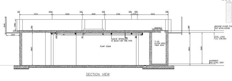
3.0 Creating the section view of an industrial building as shown in Figure and Providing appropriate hatches and dimensions wherever required.
:- First of all tak the "Xline" horizontal command and draw a horizzontal line.
:- Again, take "Xline" vertical Line and draw a vertical line.
:- Now take an "offset" of 5850 mm from horizontal line in upper side.
:- Again take offset of 300 mm from this new horizontal line.
:- Now take offset of 300 mm from bottom horizontal line below this line.
:- now trm the extra vertical line with " Trim" command.
:- Now take offset at 400 mm out side from this vertical line.
:- Again, take offset from first vertical line at a distance of 5315mm, 5320mm, 3900mm, 4720mm, 1020mm, 5025mm.
:- Again take offset of 400 mm from last most vertical line in outer side.
:- Again from 2nd last vertical line take offset of 2500 mm and 2900 mm.
:- Now take offset of 300 mm from bottom fisrt horizontal line.
:- Take "Fillet" command and fillet the slab, wall and bottom slab section.
:- Now Also fillet the "Filter feed tank" and trim the extra lines.
:- Now Again, take " Trim" Command and trim the extra lines which are not required.
:- again take offset of 300 mm from bottom most horizontal line for Tank footing section and Left side column footing.
:- with trim command trim the extra line after making rectangular box with line command.
:- Now take line tool and draw beam section from top slab.
:- Now take the "Hatch' command and fill the section of slab, wall, footing and Tank.
:- again, take offset of 50 mm from top most horizontal lines and also at 300 mm.
:- Now, Line at 300 mm fom top slab, trim at 3900 mm portion and with line command make rectangle.
:- Now, draw vertical line at left most wall/column section of 2000 mm and take offset in left side at 500 mm, and 1000mm.
:- Similarly do repeat the preocess for the right mos column section.
:- Similarly at 3900 mm section, take line command and draw vertical line of 2000 mm rectangle at both ends at offset of 200mm both side.
:- also take offset from this line at 300 mm on both side.
:- trim the line under box with Trim command.
:- Now show the dimensions for top slab for all partitions.
:- take line command and draw vertical line on top slab above tank at 200 mm offset from column and take offset of 750 mm.
:- Now trim the Lnes in slab and make MANHOLE OF 750MMx750MM.
:- also, draw a small rectangle at tank bottom.
:- take line tool and draw horizontal line left side column of length 2325 mm. and take offset from this line below it at 50 mm, and 150mm.
:- Now, at the end of these lines draw a vertical line of heigth 3045 mm, and take offset of 100 mm and close it with line command at top and bottom with zig-zag line.
:- Similary repeat the process for right side.
:- Now tak line command and draw section lines in left and right side for basement level, FGL, Ground Floor level, etc.
:- Put these line in separate layer and a line type of dotted.
:-Alos put bottom most Horizontal lines in separate layer and line weight of 30 mm.
:- Now with line command draw lines for Duct and sprimkler from top slab for water lines.
:- trim the extra lines which are not required.
:- Now with MT command write the text and levels wherever required.
:- also with "Multileader" command show the annotations like X01, X01a, X02, X03, X04,and X05.
:- Now with "Dimlinear" command show the dimensions of all the sections.
:- Thus the Sectional View of the Industrial Building have been created with all dimensions and details.