Creating Kitchen layout, Hatching of Architectural elements and sectional view of an Industrial Building in AutoCad
Introduction: Autocad is a commercial Computer Aided Design(CAD), It is marked and developed as Autodesk. It was first released on december 1982. Autocad derived from a program, which was beganed in 1977 and then released in 1979 called as Interact CAD, and also called in early documents od autocad as microCAD, Auto desk cofounder was Michael Riddle.
The first version of cad was released in december 1982 and was supported on CP/M-80 computers, By march 1986 Aotocad has became most uniquitous cad program worldwide. The file format of autocad was .dwg, and its interchange file format to DXF, have become a standard. Autocad was included support for .dwf, a format developed and promoted by Autodesk, for publishing CAD date. In year 2022 the Autocad 36th major version was released and the 12th consecutive year of Autocad foe Mac.
CAD is a technology which replaces manual drawing with automated process, if you are a drafter, desingner, architect or engineer you have been used 2D or 3D CAD programs i.e., Autocad or Autocad LT software. Autocad helps you in draft construction documentation, explore ideas for design, viaualise concepts through photorealistic renderings and gives how a design performs in real world.
Autocad mailnly used by industries, architects, engineers, city planners, project managers, graphic designers and other professionals.
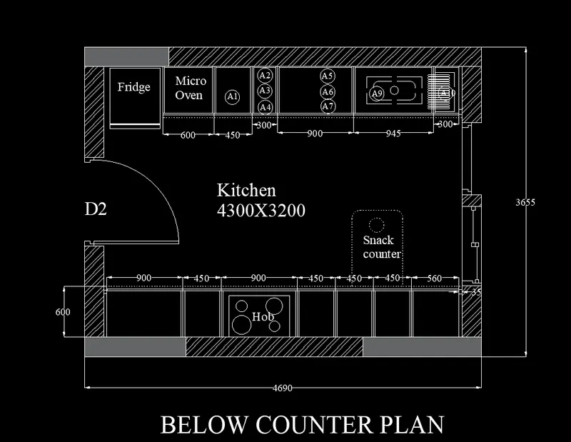
1. Aim: To create given kichen plan as a block and Layout using Autocad
Steps:
1. Open Kitchen plan file which is drawn in Challenge 6
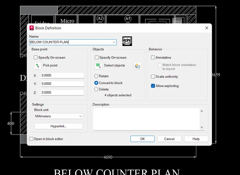
2. Select the plan and type Block and name it as BELOW COUNTER PLAN
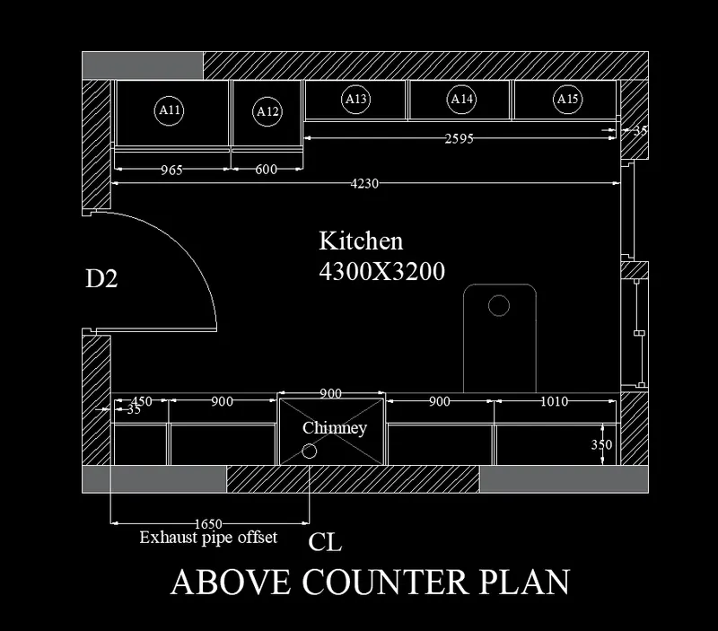
3.Select the plan and type Block and name it as ABOVE COUNTER PLAN
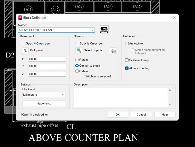
4. Type layout and them Mview and select the required space in Layout
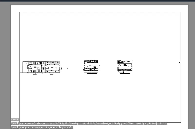
Type Mspace and adjust the required drawing in the Layout
and type PS to come out from the layout
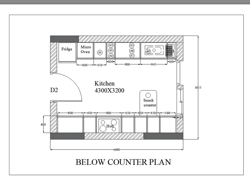
5. Type layout and them Mview and select the required space in Layout
Type Mspace and adjust the required drawing in the Layout
and type PS to come out from the layout
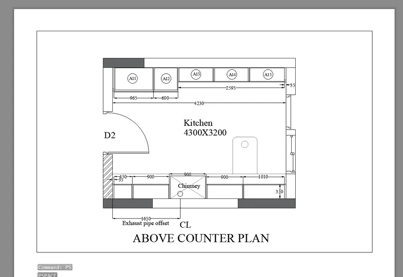
Results: Layouts of the given kitchen plan
2. Aim: To draw the given elevation by taking reference plan in the challenge 7 using Autocad
Steps:
1.Open new file in Autocad 2023, Type UNITS, use decimal and take millimeters
2. Then LIMITS, Limits of lower left corner give (0,0) and limits of upper right corner (10000,10000)
3.Use line command and draw lines by direct distance method in X direction by 11705, in Y by 12000 and in -X by 11705 and in -Y direction by 12000

Keep plan and we can use also use Xlines
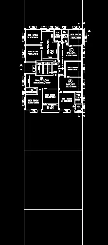
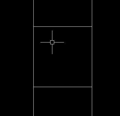
4. Offset the left vertical wall by 250, 3155, 400, 3050, 250, 4350, 250 and then Offset the bottom horizontal line by 2100 and Trim all the extra lines
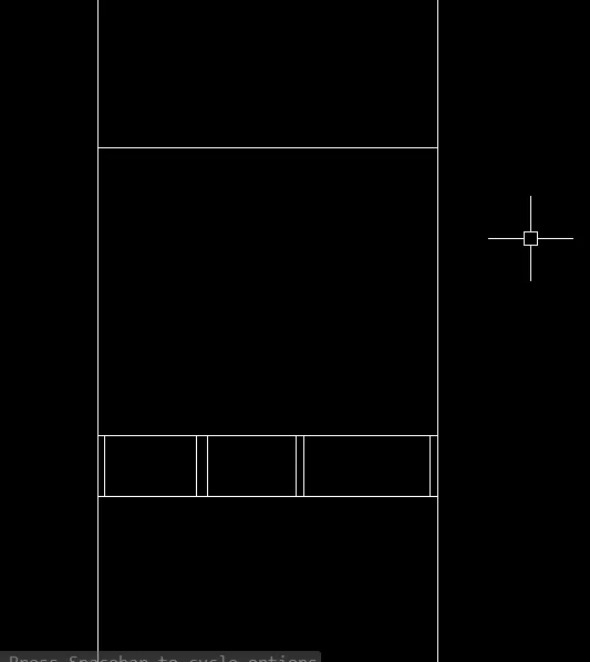
5. To create Window:
Draw the line in +X by 1500 and the in Y by 1275 the -X by 1500 and then -Y direction by 1275
The offset the Left vertical by 20,25,80,45,35,510 and 35
The use Mirror the lines in Opposite side
And delete the left and right vertical lines
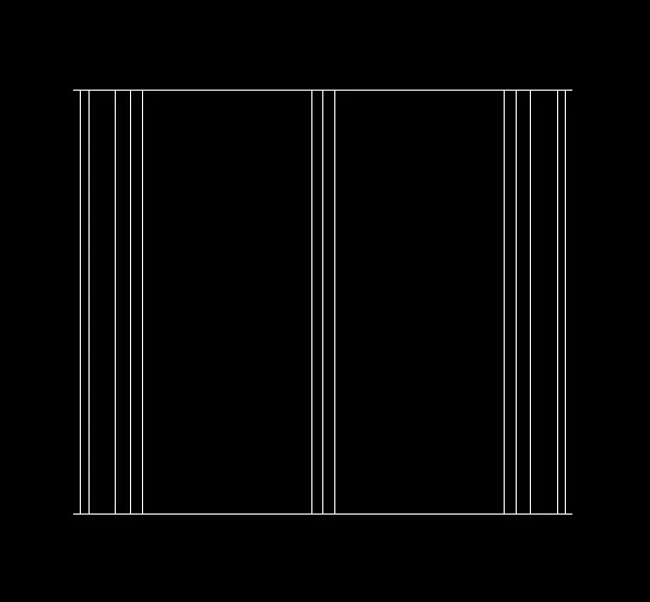
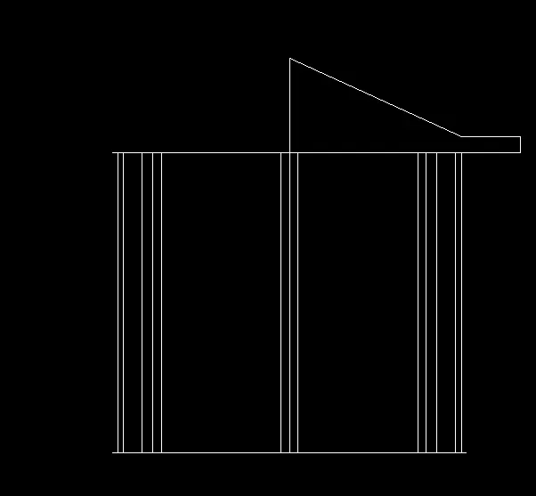
Draw the line horizontally from right vertical line in right direction by 250 and then in Y by 70 and in -X 250
Then Extend the middle vertical line by 400 and then join the previous point and this point
And select the lines and mirror the lines in opposite direction
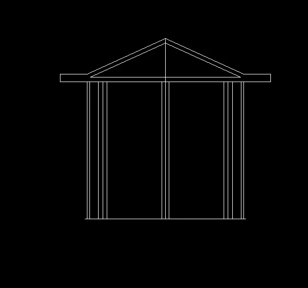
Then offset the inclined lines and horizontal line by 40 in inward direction and trim the lines
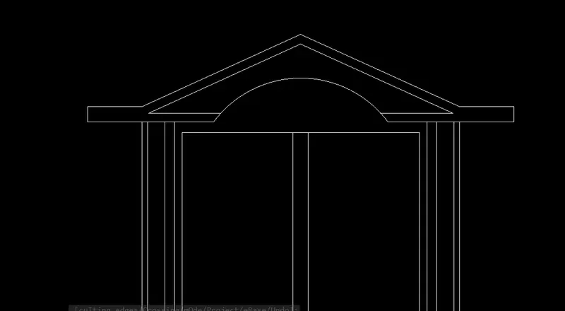
The arc is drawn by 3 point, create the points first point is 180 from the left inner vertical line and then second point 200 from the horizontal and the third point is 180 from the right vertical line. And then draw Arc by joining these 3 points and Trim the extra lines
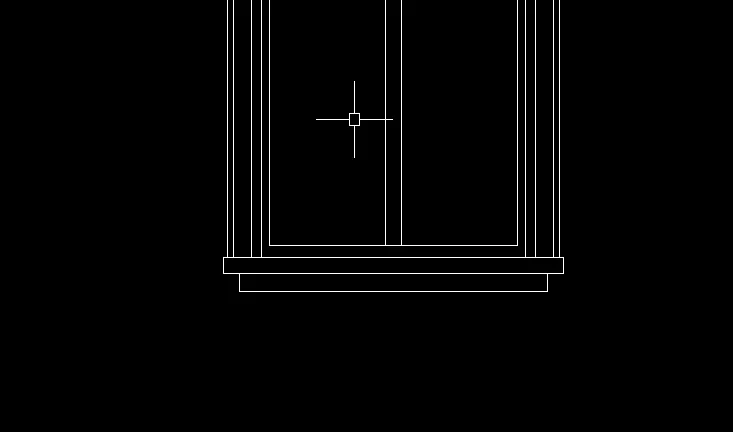
Use off set command offset the bottom hori line in downward dir by 70 and then 80 and using line draw vertical lines and trim extra lines
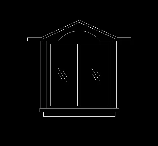
6. To create Grills:
Draw the rectangle of size 3050X1200
And then offset the rectangle inward direction by 50, 150
then from right and left top corners extend the line by 150 and offset the horizontal line by 110 and the 40, using line draw vertical lines
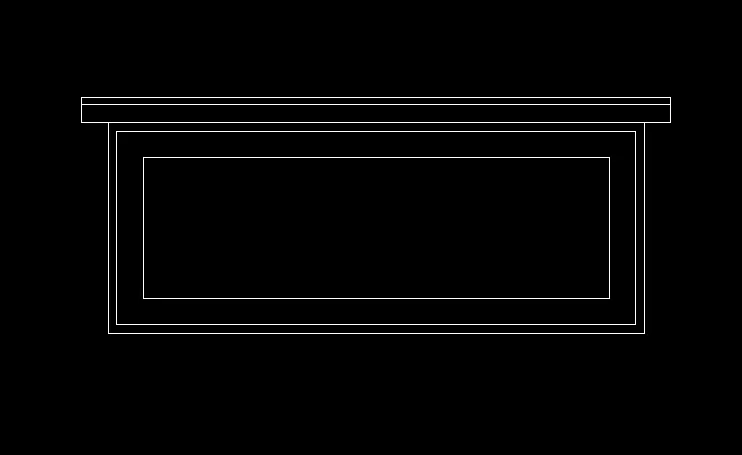
By using Line command, draw the required lines
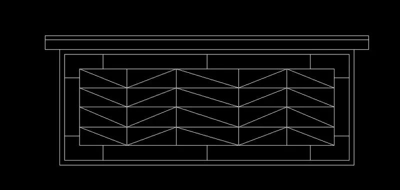
7. To create Balcony:
Draw the rectangle of 1250X2070 and explode
Offset the bottom horizontal line in inward direction by 820,25,85 and then Offset the top horizontal line in inward direction by 75,75
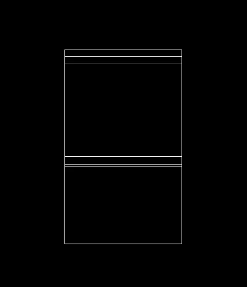
Extend the top 3 horizontal line by 700, and then draw vertical line and offset that line by 450 in left direction
Draw the required inclined line and trim the extra lines
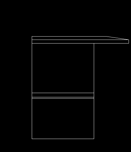
Draw the required lines using Line command
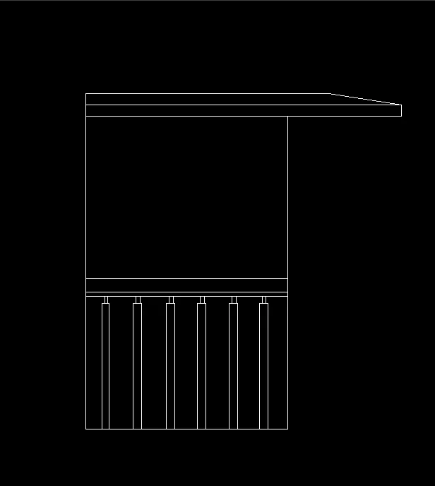
8. Draw 450 horizontal and 75 in Y, and draw inclined line 25 above the horizontal line
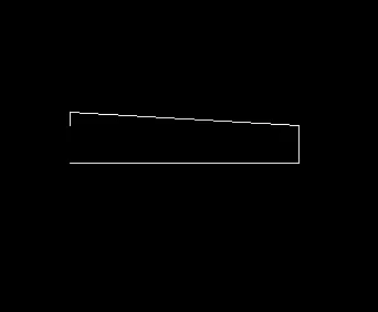
9. Offset the right vertical line by 400
Keep the sunsides on both sides by at a distances of 2100,2460, 2800,2800 and
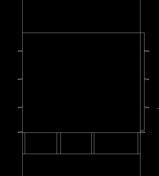
After removing Xl lines
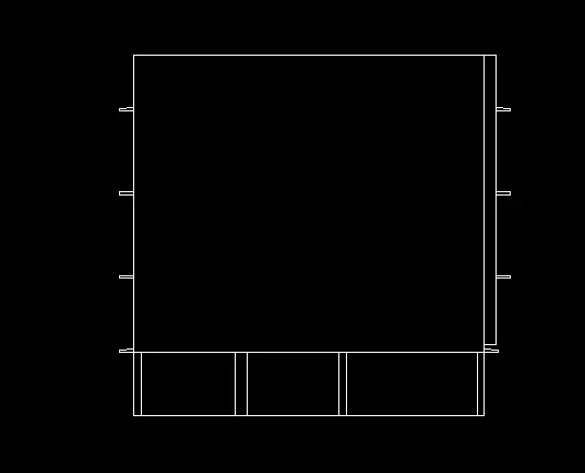
10. X lines are drawn and windows are placed and place veranda grills by a distance of 3650 from left vertical line
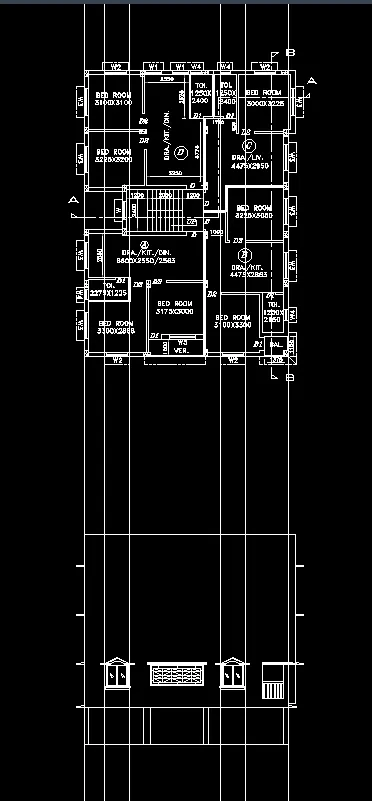
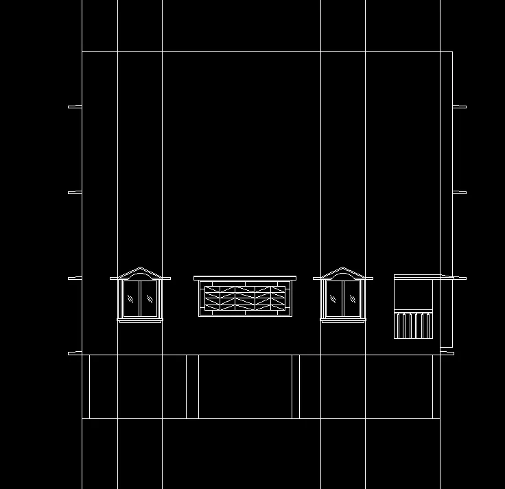
11. Copy the windows balcony and veranda and place vertical upward by a distance of 2800 and 5600
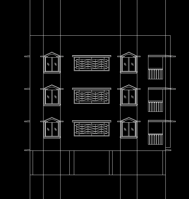
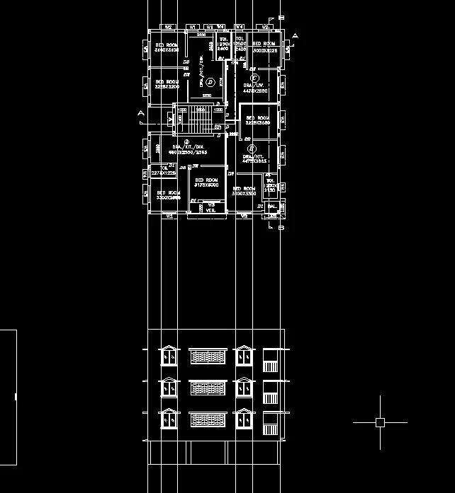
12. Remove xlines and offset the bottom horizontal line by 150 upward and trim the extra lines
Draw the rectangle and offset it and keep in left top corner and then copy it in required places
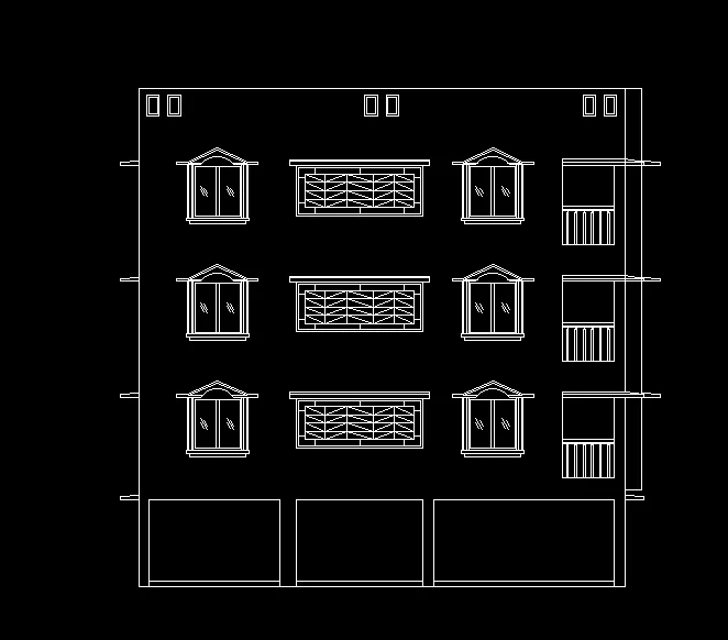
13.Draw a vertical line from left corner at 2200 distance of length 3300 then in X by 2750 and in -Y by 1350 then in -X 2750
Then from that point draw line of 4900 in X dirction and the 1950 in -Y
the offset the vertical line by 250 in left direction
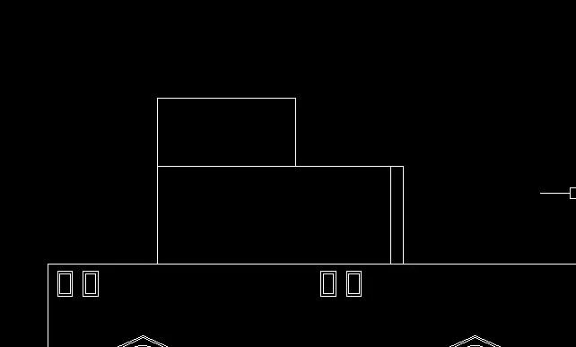
Draw the door using rectangle and line command
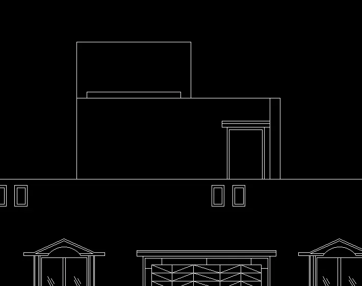
14. With Xlines
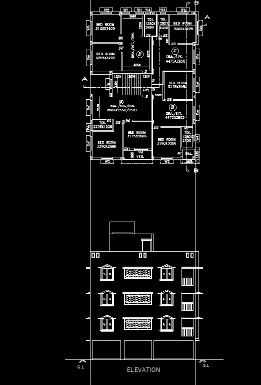
Result:
Write the required Text using Mtext command
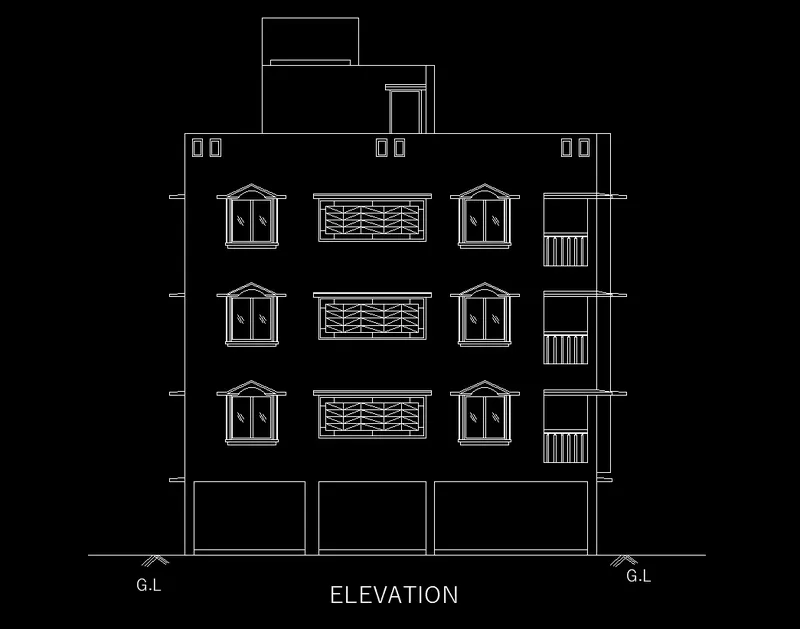
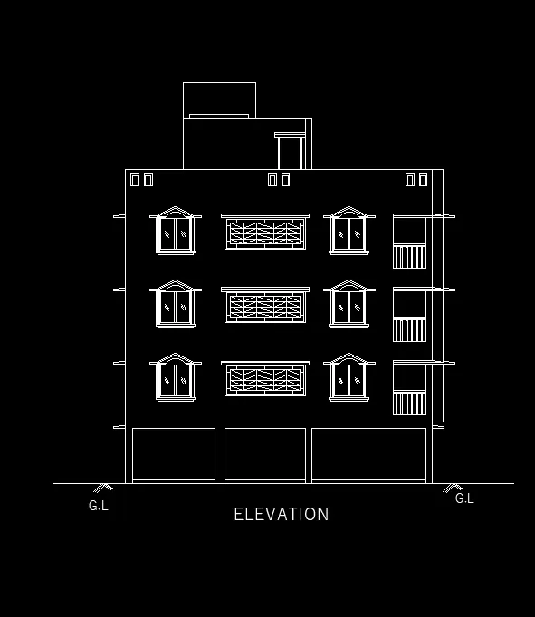
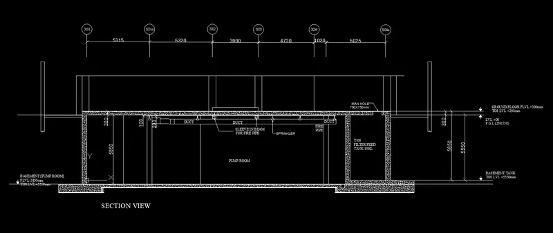
3. Aim: To create the Sectional view of the given industrial building using Autocad
Steps:
1.Open new file in Autocad 2023, Type UNITS, use decimal and take millimeters
2. Then LIMITS, Limits of lower left corner give (0,0) and limits of upper right corner (10000,10000)
3. Draw horizontal and vertical Xlines and
offset the vertical xline in right direction by 5315, 5320, 3900, 4720, 1020, 5025
and offset the horizontal in upward by 5850 and then 2000
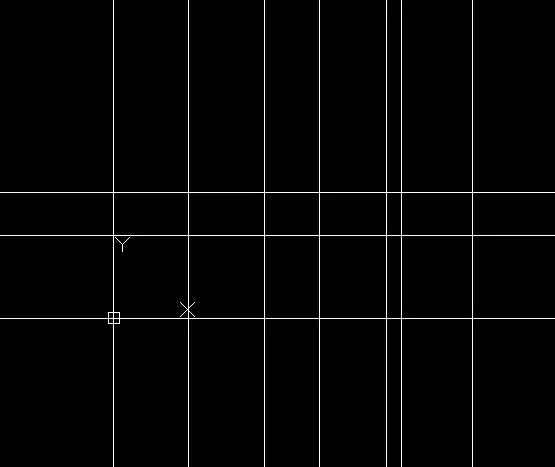
After trimng Xlines
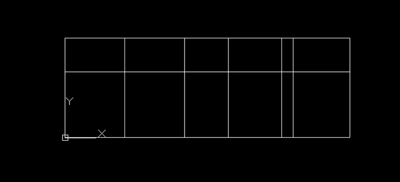
4. Offset the left and right vertical lines by 400 in outward direction and the top 2000 vertical line length part is offsetted 200 in inward direction and trim the extra lines
the horizontal line at 6150 is offsetted 300 in downward direction
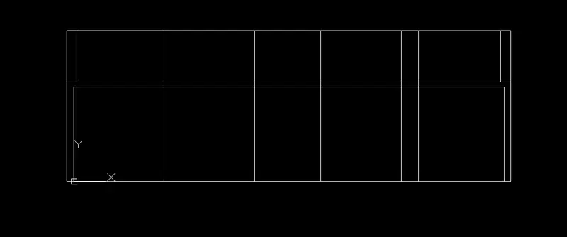
5. The second vertical lines from both left and right are offsetted by 200 on both the directions
Trim the extra lines
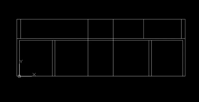
6. The middle vertical lines are offsetted by 300 an both the sides and trim the lines extended to pump room
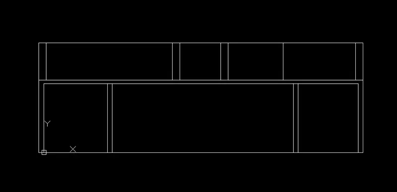
7. To create a duct, the Left support for duct is at 200 from top horizontal line,
and taken as 700X550 and a duct of size 400 is considered and 25mm it is moved down after 700mm from support
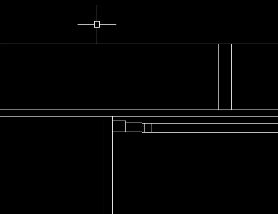
8. Draw the Duct of size 300 depth and 300 width, and use line command draw required lines
And offset the horizontal line by 35 in downward direction
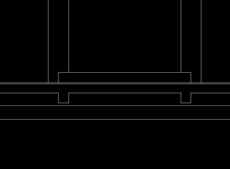
9. Offset the horizontal line above the duct in downward direction by 35 and then 65
The draw the sprinkler using line command, and copy it where required
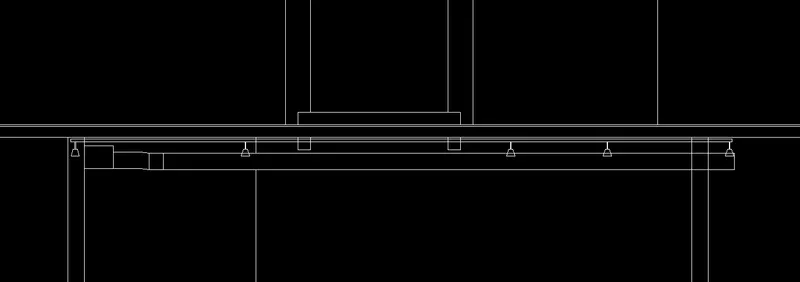
10.Offset the right inner vertical line by 3000 and 400 in left direction
and offset the bottom horizontal line by 300 in upward direction
A manhole of 750mm length is created at a distance of 300 from right inner vertical
Trim the unnessecary lines
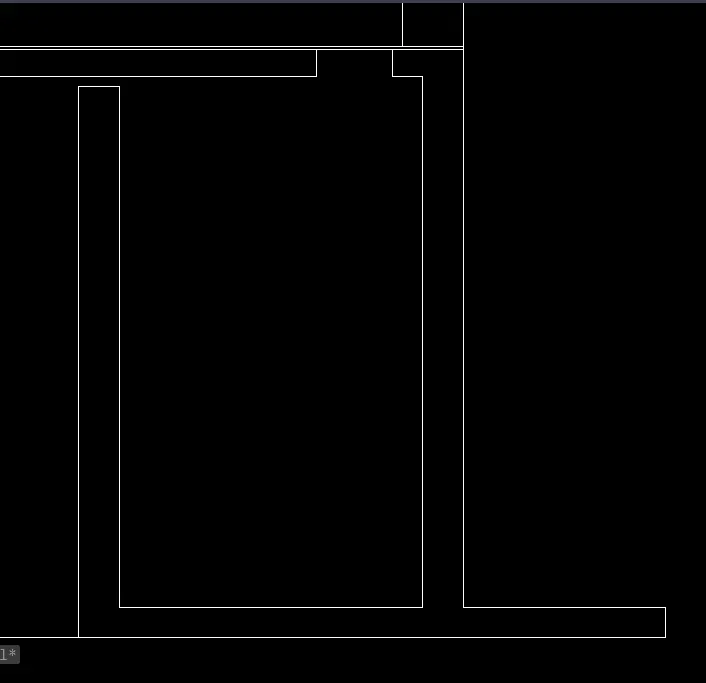
11. Offset the bottom horizontal line from that line by 35,300 and by 700 from the bottom horozontal line
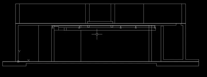
12. Draw the extra using Line command and draw dotted line at required places
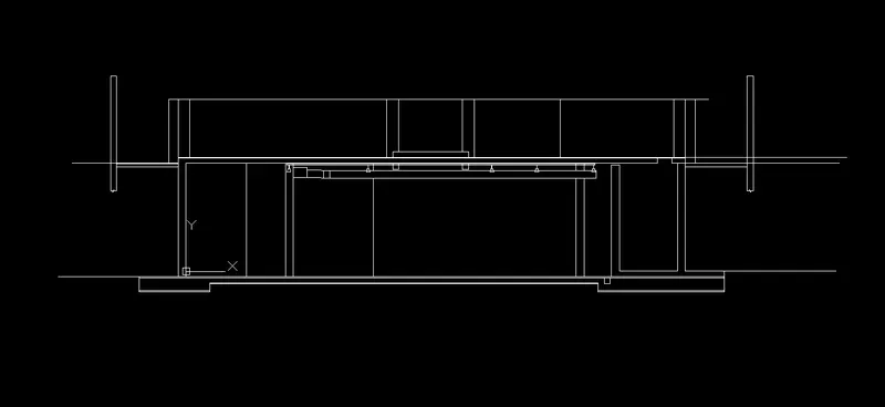
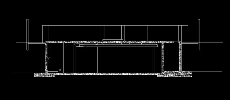
13. Using hatch command, orovide required hatch
14. Measure the domensions and provide the required text using Mtext, font style used is Times New Roman Greek
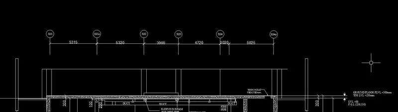
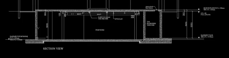
Results: