Creating Kitchen layout, Hatching of Architectural elements and sectional view of an Industrial Building in AutoCad
1.Create the layouts of the Kitchen and provide hatches pattern as shown. Also, use blocks wherever required. Provide appropriate dimensions in the plan. Assume the size of doors, appliances and others as per the standards.
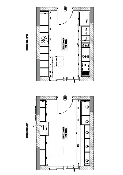
AIM:
To Create the layouts of the Kitchen and provide hatches pattern and use of block
COMMAND ARE USED:
- Units
- Limmax
- Limits
- Line
- Offset
- Text
- Block
- Layer
- Dimension
- Dimension style
- Hatch
PROCEDURE:
- First we set an unit as per the engineering and dimenion of mm have choosed
- Next we et limmax and limit spec @0,0 and 20,20
- Then z enter and a enter
- Inner layout 3200mm and 4300mm repectively
- Take the offset of the dimension
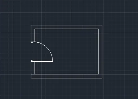
- Draw the door as per the size of the 1200mm
- To copy the same plan for above the counter plan
- To Fill the hatches in the required areas
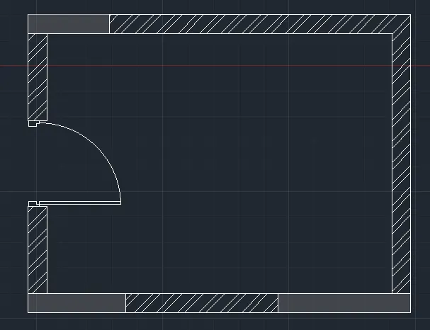
- To take reuired dimenion of fridge
- To offset and offset it to the desired distace to get the Micro Oven
- In the command offset and offset it to the horizontal distance of 350,450,900,450,450 and 560
- In the command offset and offset it to the vertical distance of 600
- To take an line type and load the dotted lines
- Command text to text the given annotations
- To gives dimensions to given the dimensions to your plan
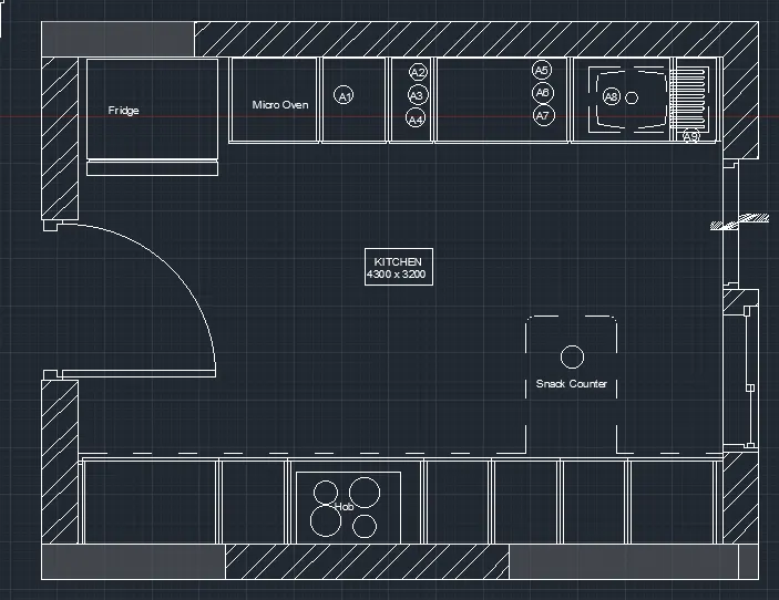
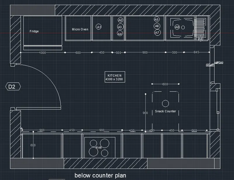
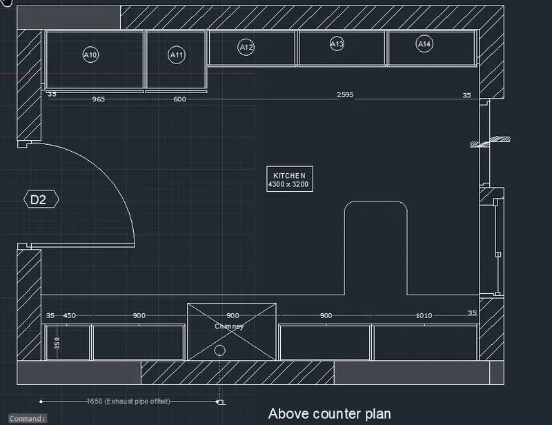
- Text below the drawing at below and above the couter plan.
RESULT:
Finally we get the kitchen layout of given figure
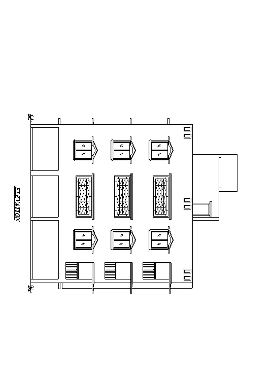
2. Create the elevation of the plan created in the Challenges 7 and apply proper hatch in the walls, doors, windows, and other architectural elements. Refer to the dimensions in Plans and sections in Challenges 7.
Refer to the elevation that needed to be created.
AIM:
TO Create the elevation of the plan as per the specification of the drawing
COMMAND ARE USED:
- Units
- Limmax
- Limits
- Line
- Offset
- Text
- Block
- Layer
- Dimension
- Dimension style
- Hatch
PROCEDURE:
- First we set an unit as per the engineering and dimenion of mm have choosed
- Next we et limmax and limit spec @0,0 and 20,20
- Then z enter and a enter
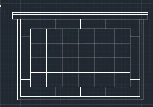
- To draw the window
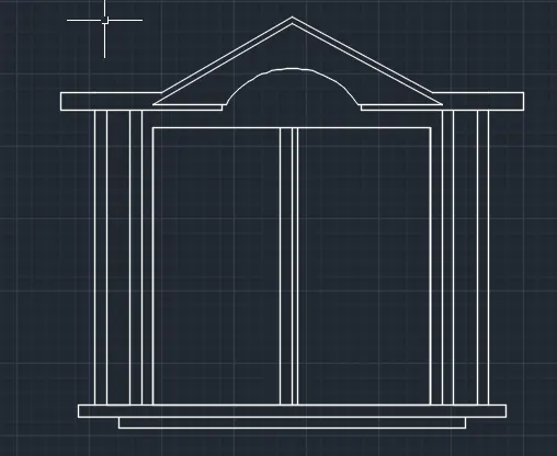
To creat an block named as window
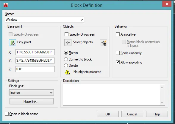
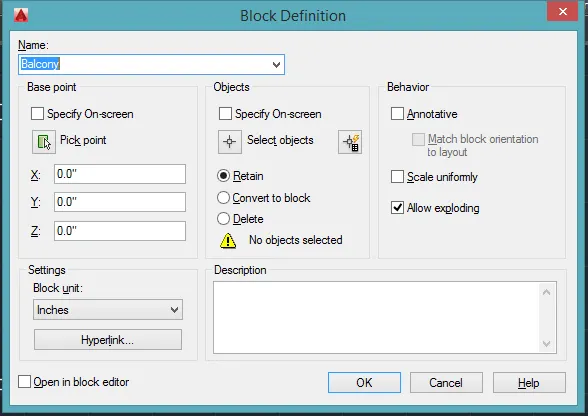
And we draw an balcony in the required dimension
To create an block and named as balcony
Next we draw an to the another window 1
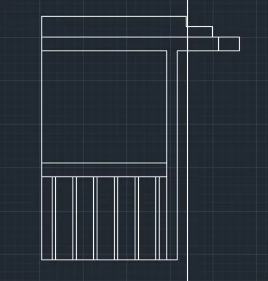
Create the block named as window 1
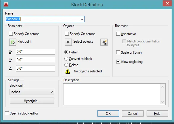
- To create the outer layout
- Next we do insert the block required specific place
- Draw an the upper of the head room
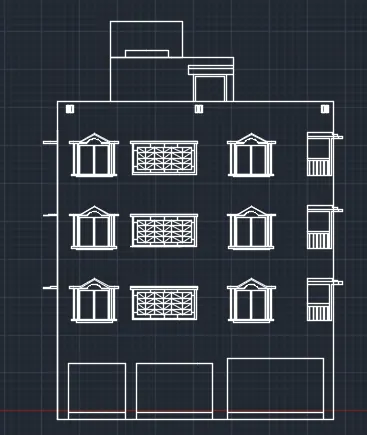
Text the elevation of the drawing
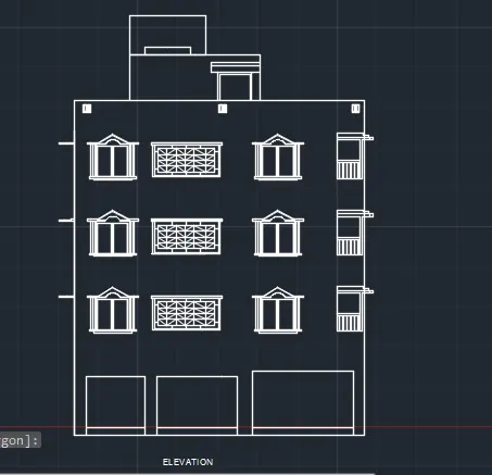
Create the block and named as elevation
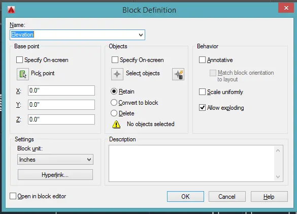
RESULT:
Finally we draw the elevation to refer the previou challenges
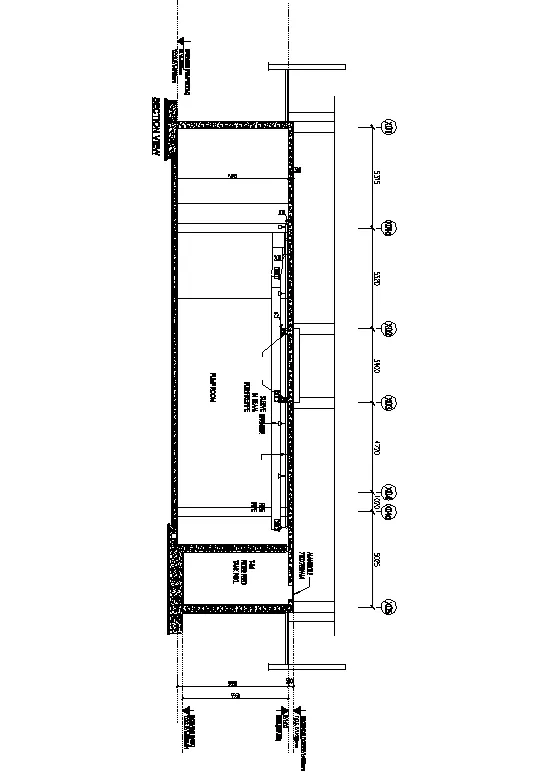
3. Create the section view of an industrial building as shown in Figure. Provide appropriate hatches and dimensions wherever required. Also, provide annotations to the drawing.
AIM:
To Create the section view of an industrial building
Command are used:
- Units
- Limmax
- Limits
- Line
- Offset
- Text
- Block
- Layer
- Dimension
- Dimension style
- Circle
- Arc
PROCEDURE:
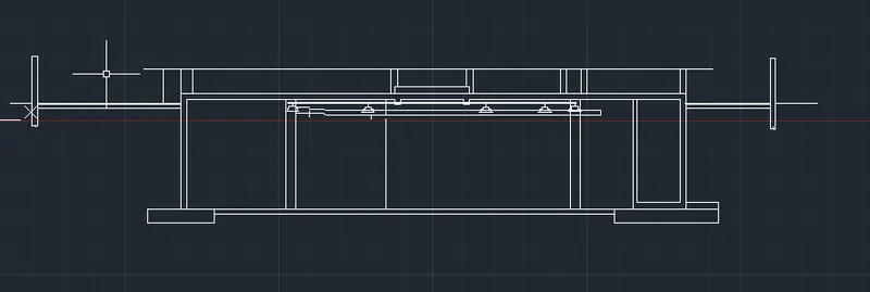
- First we draw the line so type l to draw the lines .
- We haunching at the Hatch AR.CONC.
- Draw an rec to draw the rectangle.
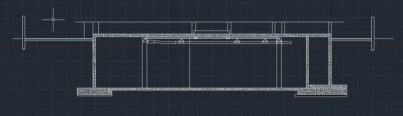
- Take the LT command for the dotted lines
- Drawn c to the circle
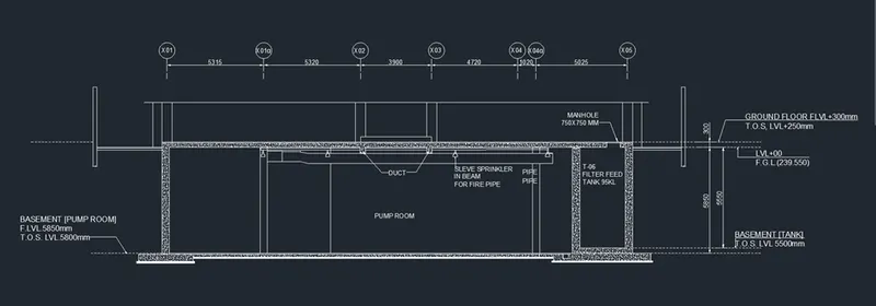
- Command Mt to draft the text
- Take an dim to draft the dimensions
RESULT:
Finally we get an section view of the plan