Creating Kitchen layout, Hatching of Architectural elements and sectional view of an Industrial Building in AutoCad
Create the layouts of the Kitchen and provide hatches pattern as shown. Also, use blocks wherever required. Provide appropriate dimensions in the plan. Assume the size of doors, appliances and others as per the standards.
Aim: To create the Kitchen Layout and provide dimensions as shown in the figure.
Introduction: The given kitchen layout consists of two plan given. The plan also consists of hatch and other kitchen utilities such as chimney etc., The given plan is recreated using the dimension given.Blocks and attributes options are also used to provide markings in the layout.
Steps:
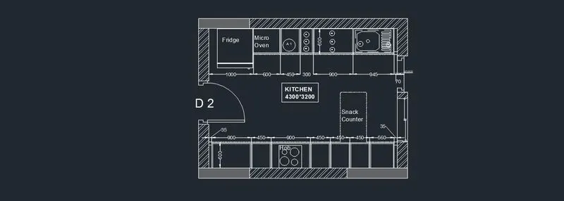
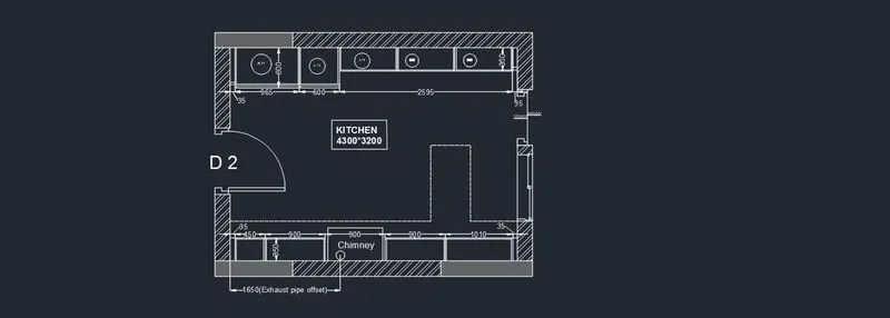
- Initially a rectangle of the given dimension is created
- Then a offset of 230mm is done to provide thickness of the wall.
- The openings for door and ventilation are given with the assumed door size.
- Then as per the dimension given the utilities of the kitchen are drawn using the offset option and the extra lines are trimmed off.
- The snack counter is drawn as per the dimension and the linetype is changed using the linetype command and scale is fixed as per requirement.
- The hatching of the wall are done using the hatch command
- Then the dimension are marked after setting the dimension style.
- In this plan the dimensions are marked continuously using the command dimcontinue
- The markings like A1,A2 are given by creating a circle and using Attdef command with the tag markings attributes are defined and placed inside the circle and are converted into blocks.
- Then the markings are inserted inside the layout using the insert command.
- The layout is copied and the 2nd layout is created and edited as per the given plot.
- Then using the mtext option the utilities, and title of the kitchen are written and the diagram is finished.
Results: The given kitchen layouts are drawn sucessfully.
2. Create the elevation of the plan created in the Challenges 7 and apply proper hatch in the walls, doors, windows, and other architectural elements. Refer to the dimensions in Plans and sections in Challenges 7.
Aim: To Create the elevation of the plan created in the Challenges 7 and apply proper hatch in the walls, doors, windows, and other architectural elements.
Introduction: The given elevation diagram is of the plan created in previous challenge 7. The dimension and other references are taken from that project and the given plan is drawn. The given elevation consists of windows, doors and other elements in the plan with respect to the given layout. The challenge 7 project file is used here as the elevation is drawn for that project.
Steps:
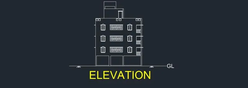
- Initially projection lines are drawn from the plan created using the xline command in vertical y direction.
- Then a line is drawn in horizontal direction for setting the GL of the elevation.
- Then using the offset command the GL line is offsetted in vertical y direction as per the dimesnions i.e 150,2450,2850,2850,2850,1000,2450 respectively as per the floor to floor height acquired in the project.
- Then the extra lines are trimmed off.
- The window of size 900x1200 is drawn and the projections for window is drawn by offset command.
- For projections 1st the rectangle is exloded using the explode option then a 50mm offset of 3lines is drawn on all sides of the rectangle
- At the top using arc command a arc is created the a traingle is drawn with respect to the dimensions of the arc. Then the lines are connected and the window is converted into a block.
- Then the opeing verandah window at the middle is drawn by drawing a rectangle of the acquired size.
- Then offset of 50mm is done and another rectangle is drawn inside of required size and zig zag lines are drawn to make it look like a grill. A sunshade is also drawn at the top. Then it is converted into a bock.
- For balcony portion a line of given balcony size is drawn and a offset of 100mm is done in downward direction.
- Then the grills are done by line command of approximate sizes,a sunshade is also drawn and are converted into blocks.
- Then at a lintel level of 7' the blocks are inserted at each floor levels using the insert command.
- Then a door is drawn using the rectangle command and placed at head room level.
- Then small rectangle is drawn of assumed size and offset is done and placed at top for aesthetic purpose and markings are provided using the same text style as the previous project.
Results: The given elevation drawing and windows,doors and other architectural elements are created sucessfully.
3. Create the section view of an industrial building as shown in Figure. Provide appropriate hatches and dimensions wherever required. Also, provide annotations to the drawing.
Aim: To Create the section view of an industrial building as shown in Figure and to provide appropriate hatches,annotations and dimensions wherever required in the drawing.
Introduction: The given diagram consists of a section view of drawing with hatch and dimesnions. The section view is drawn using the centreline markings given.
Steps:
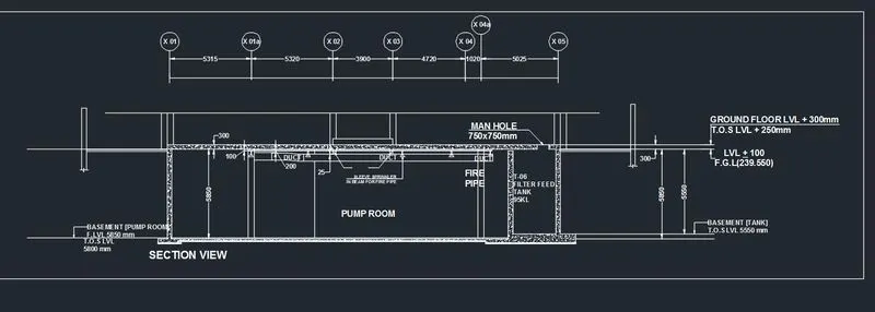
- Initially a line is drawn as per the dimensions of the centre line markings given.
- Then the section diagram line is drawn with respect to the centrline markings.
- A offset of 300mm is done to provide the thickness of the wall.
- Then a offset of 5850mm is done as per the given dimension to the set the width of the section diagram.
- A cover of 50mm is provided at the top and bottom of the section diagram.
- Then a manhole of given size is created at the left corner of the section diagram using the offset command.
- Then a duct pipe of assumed size is created at 300mm from the top. Then fire sprinklers are provided as per the plan.
- The fire sprinklers are created,converted into blocks and placed in the plan.
- Then the walls are hatched using the hatch command.
- Then a definite dimension and text style is fixed and the measurements are marked.
- Using mleader and after defining the leader style leader are inserted in the drawings to annotate the drawings.
- The centre line markings are given by drawing circles and assigning attributes inside it and converting into blocks and inserted in the drawings.
Results: The given section drawing is created sucessfully and proper dimensions and annotations are given as per the requirement.