Creating Kitchen layout, Hatching of Architectural elements and sectional view of an Industrial Building in AutoCad
KITCHEN PLAN
AIM: To create a kitchen with their components and their specifications with mention proper dimensions.
INTRODUCTION: Create the layouts of the Kitchen and provide hatches pattern as given and, use block. Provide appropriate dimensions in the plan. Assume the size of doors and others as per the standards.
PROCRDURE:
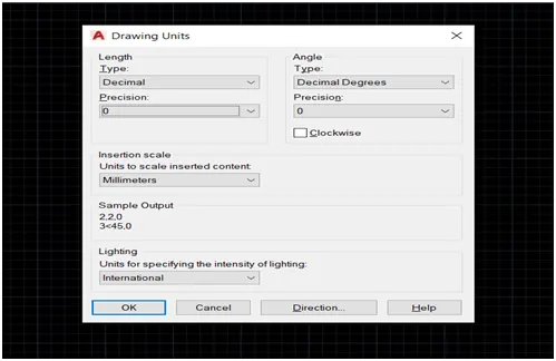
1.Open the auto cad and set the unit with unit command and choose the unit in mm
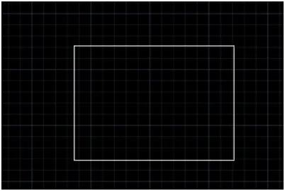
2.First create a box 4230,3200 mm
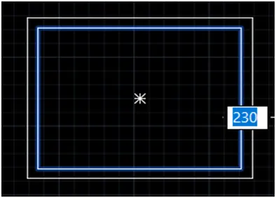
3.Then go for offset 230mm for exterior wall
4.Create a line midpoint as shown in figure
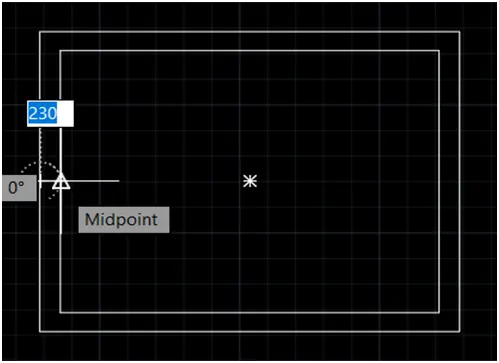
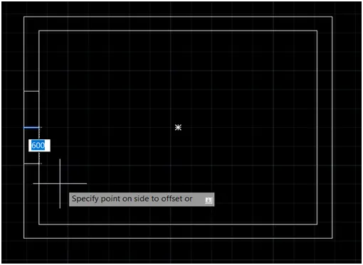
5.Go for offset 600mm both side
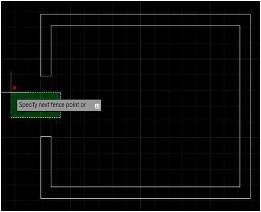
6.Then trim that portion as shown in figure
7.Create a window from midpoint 900mm
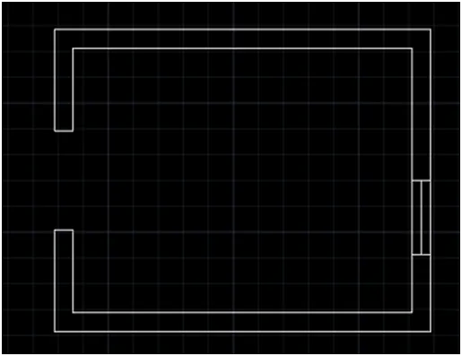
8.create a overlap line as shown in figure
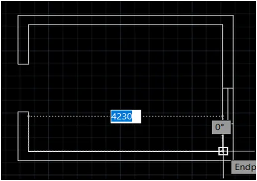
9.Then move the line 600mm up word
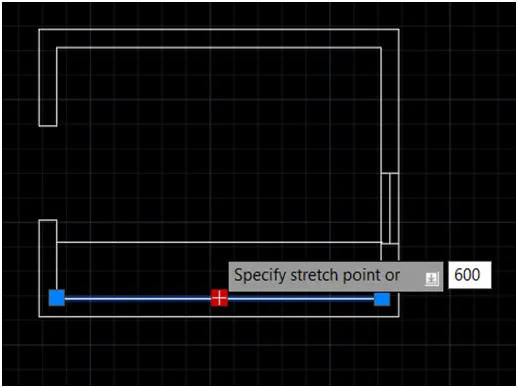
10.Again draw the overlap line 600mm as shown in figure
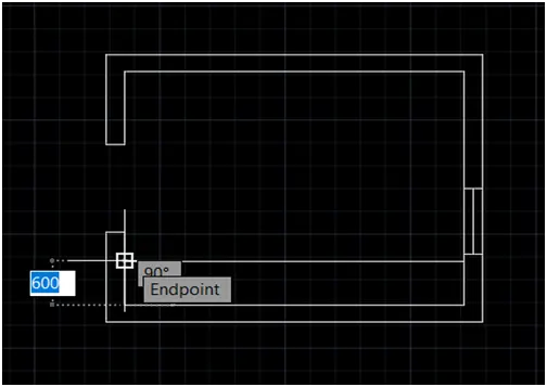
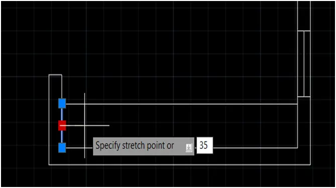
11.Then move the line 35 mm right sides
12.Then go for the offset 900mm
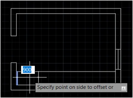
13.Offset 450mm
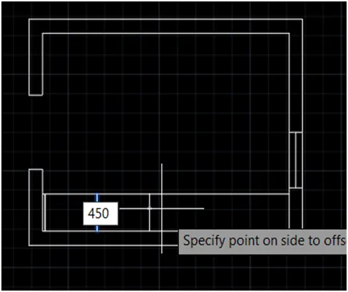
14.Offset 900mm
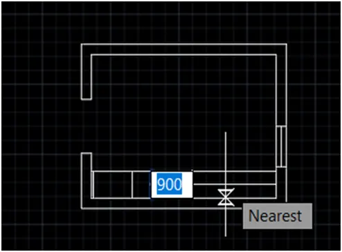
15.Again offset 450mm, 450mm, 450mm, 580mm, all the line go for the thickness of the drawers 20mm both side then trim the separate doors
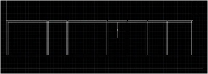
16.Then same create upper side of drawer the size is 1280mm, 900mm, 300mm, 450mm, 600mm, 685mm then create a components and place or insert the component Then create a surface for the hatch then hatch the surface then delete the surface then create a slider size is 800mm
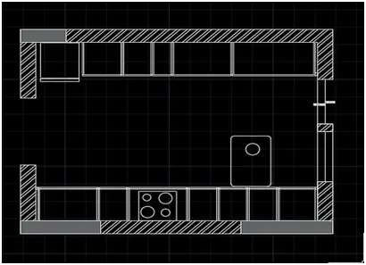
17.Then go for the dimension of the drawing and mention dimension in the drawing
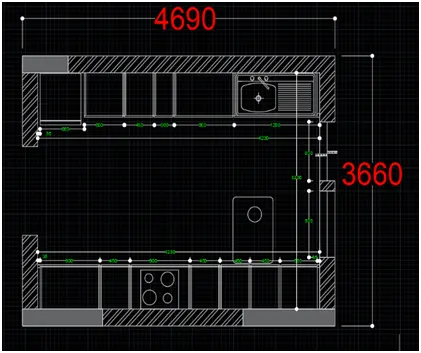
18.Then go for text command and give the detailing of the drawing
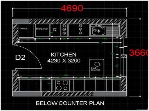
19.Copy the first drawing and delete the internal portion.
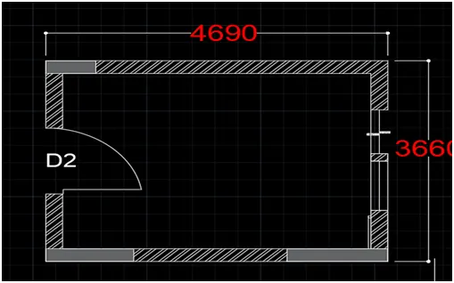
.20.Go for line and draw the overlap line and move the 350mm ang get offset 250mm
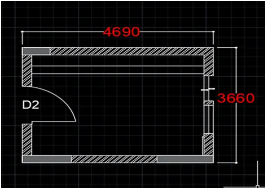
21.Go for the below 20mm offset on both line then create vertical line 350mm right side overlap and move the 35mm left side then 865mm, 865mm, 865mm, 600mm, 965mm then offset all line both side 20mm then join the above line Then trim the separation of the drawer
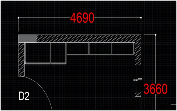
22.Then go for the below drawer Create a line 350mm overlap right side then move the 35mm left side then offset 1010mm, 900mm, 900mm, 900mm, 50mm then join the line and trim as shown in figure then create a box and draw diagonal line Then go for the text command and give the detail of the drawing then go for the dimension and mention the dimension of the drawing.
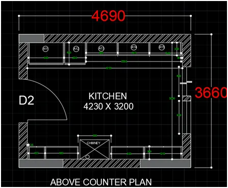
23.Go for the block command.
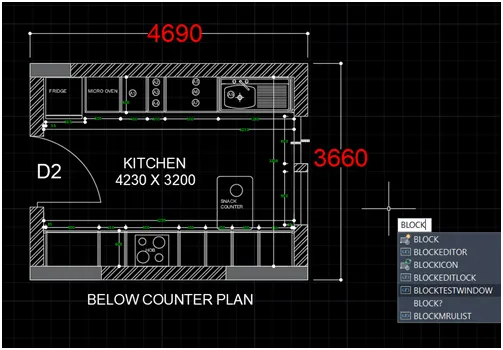
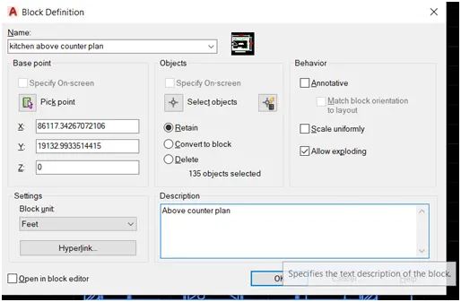
24.Give the name and choose the pick point and select the object and choose the scale and if required description Then ok
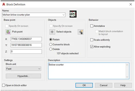
25.Go for the block command.
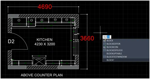
26.Give the name and choose the pick point and select the object and choose the scale and if required description Then ok.
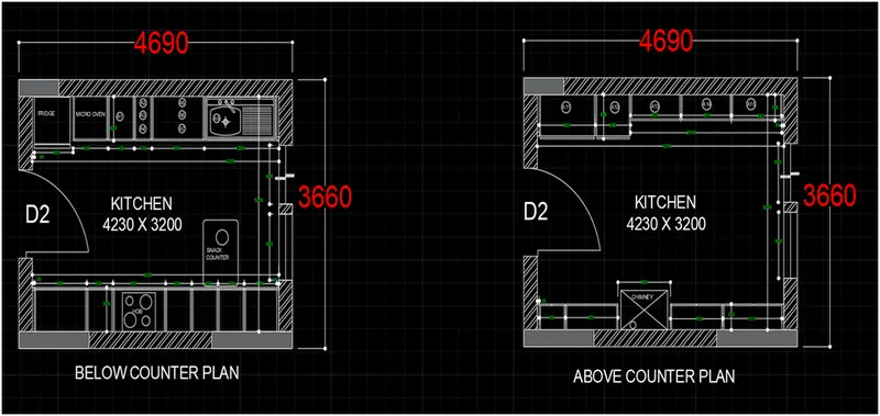
RESULT: The size of the kitchen is different as shown in figure the original size of the drawing is 4230 x 3200 mm.
ELEVATION
AIM: Create an elevation of previous create house building plane.
INTRODUCTION: Create the elevation of the plan created in the previous Challenges and apply proper hatch in the walls, doors, windows, and other architectural elements. Prefer to the dimensions in Plans and sections in previous Challenges. Prefer to the elevation that needed to be created.
PROCEDURE:
1.create a line 1195 as my previous plane
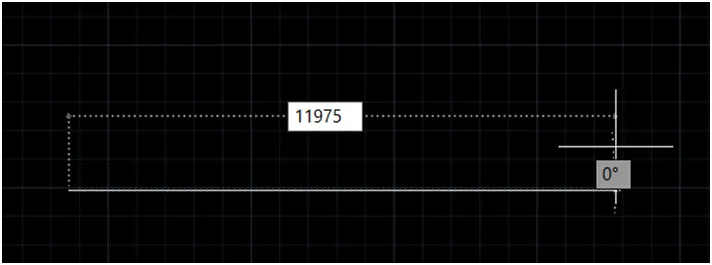
2.To continue 2450 vertically
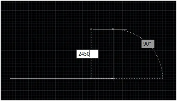
3.To continue 2450 vertically other side
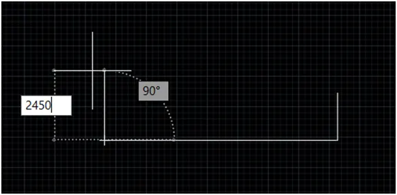
4.Offset 300mm as wall thickness
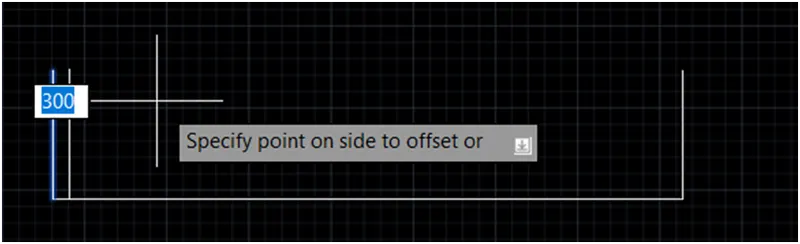
5.To continue 3184mm
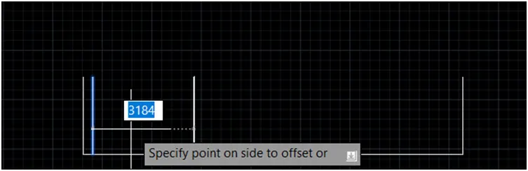
6.To continue 450mm, 3041mm, 300mm, 3325mm, 1075mm, 300mm.
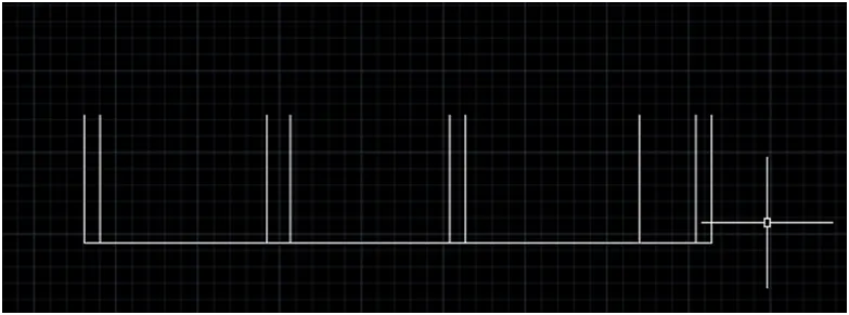
7.Join the line both side as shown in figure.
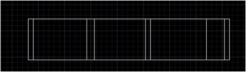
8.Go for offset 150mm down word side
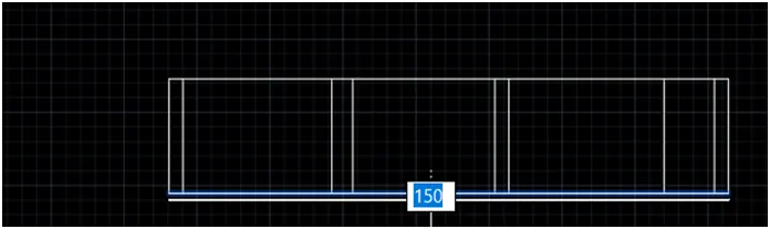
9.Extend the line
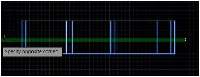
10.Then trim the middle portion as shown in figure
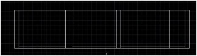
11.Offset 2850mm upper line upper side Three times
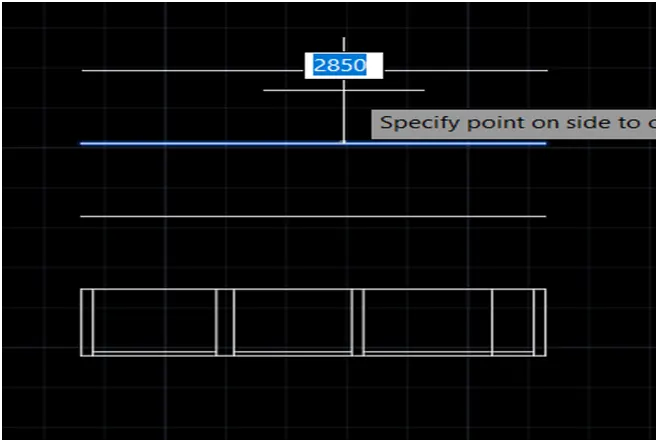
12.Again offset 1000mm and 2950mm same line
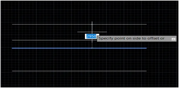
13.Join the line
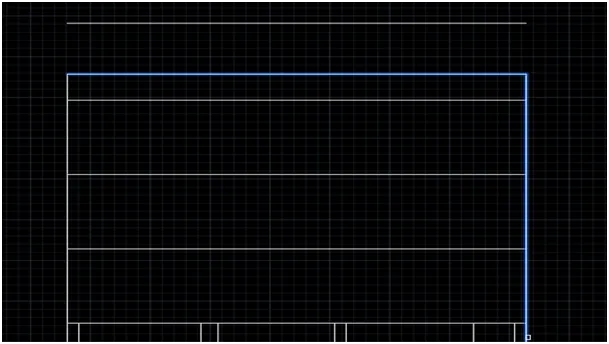
14.Again offset 2100 on every floor line To up side as shown in figure.
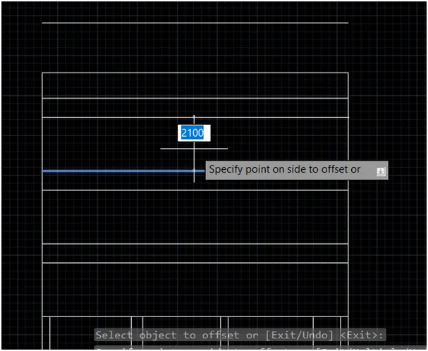
15.Then delete the floor line which is 2850mm offset or as shown in figure
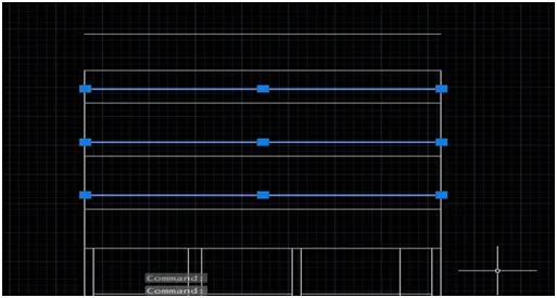
16.Stratch the line at top floor
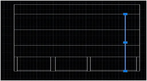
17.Then trim the bottom side This line
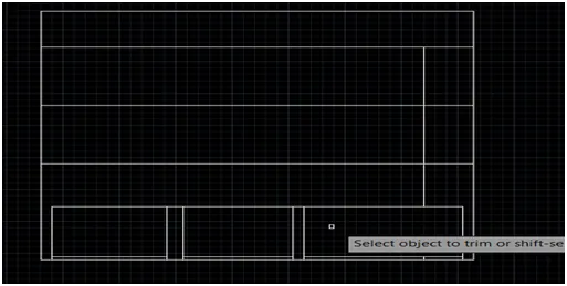
18.Then create a window Which is 1200mm x 1200mm
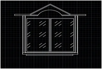
19.Go for a block command and give the name and select the pick point and select the object and select the unit as Then ok
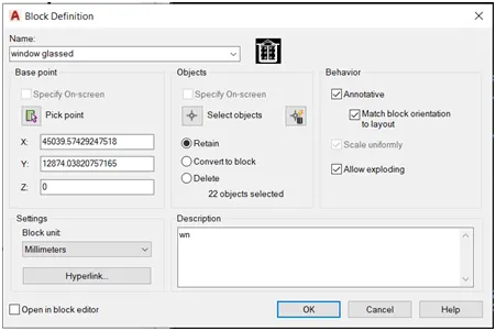
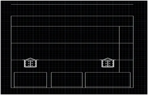
20.Insert the window and plane the first floor as given distance
21.Create another slider as shown in figure
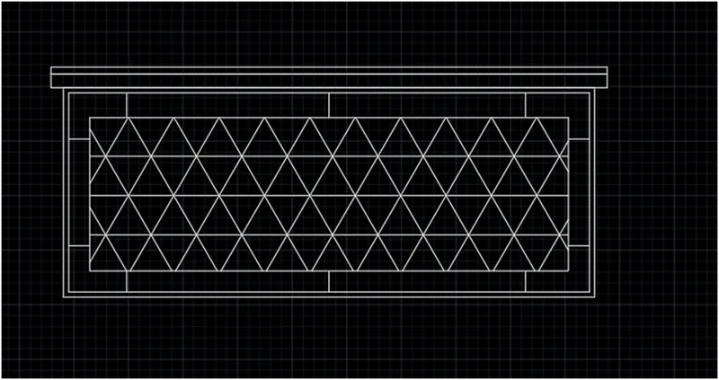
22.Go for a block command and give the name and select the pick point and select the object and select the unit as then ok.
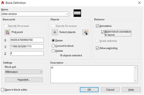
23.Then insert the drawing and place the mid portion
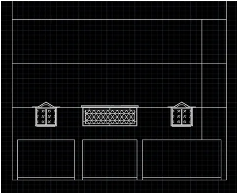
24.Then offset the 450mm as a side portion of the back wall
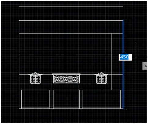
25.Then create a balcony as given figure
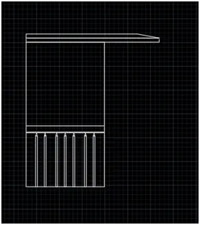
26.Go for a block command and give the name and select the pick point and select the object and select the unit as then ok.
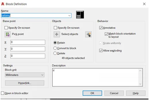
27.Then insert the balcony and place the cornet and delete the line
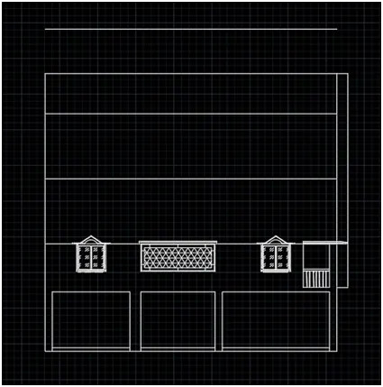
28.Copy pest the object or also use the mirror command and individually place one by one. Then delete the reference line
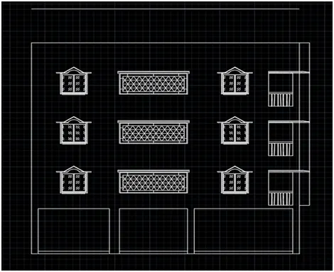
29.Then create a top door and top tower as shown in figure
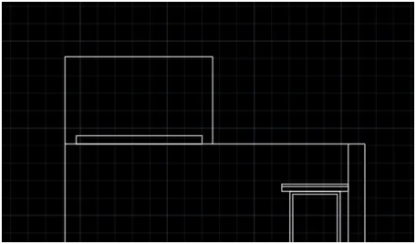
30.Then create a boxes and place the parapet wall as shown in figure and also create a cantilever and place the top of the window as shown in figure.
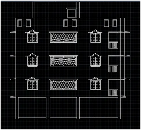
31.Then write the name of the drawing and shown in portion.
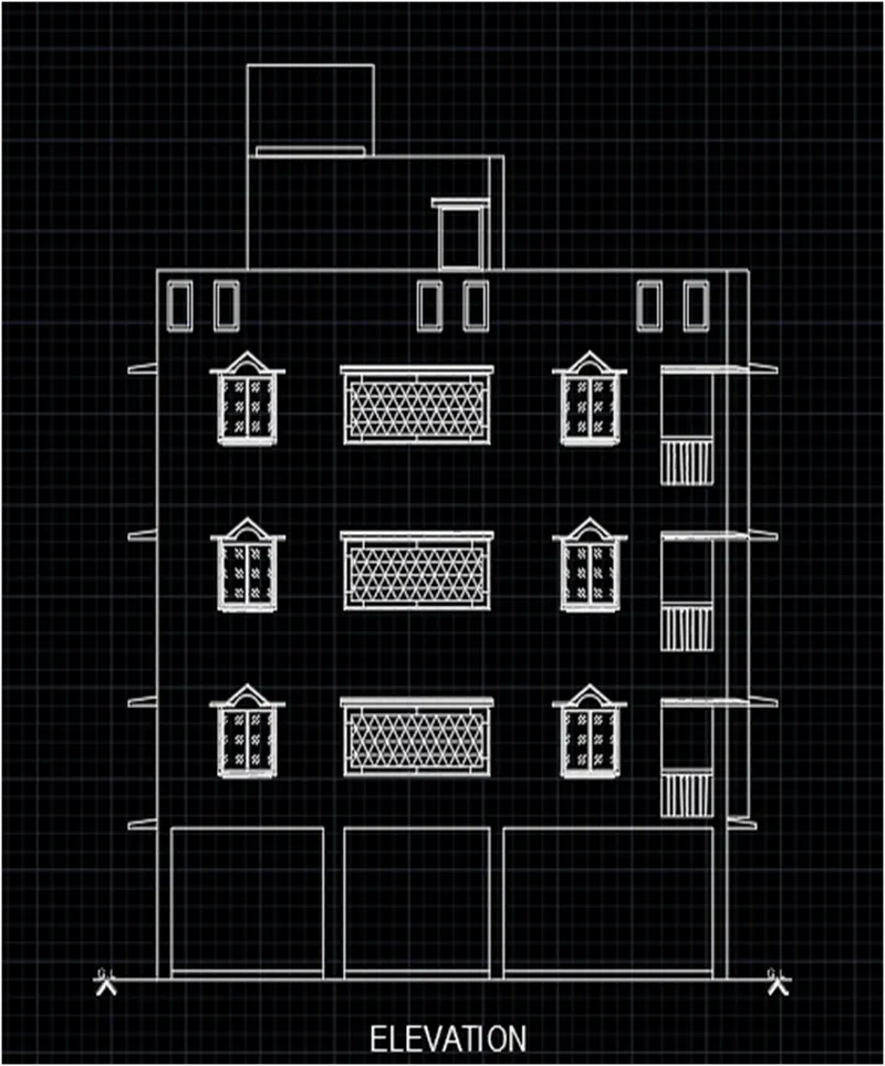
RESULT: I can create an elevation for a previous plane with their dimensions.
SECTION
AIM: To crate section of a industrial building and hatch the
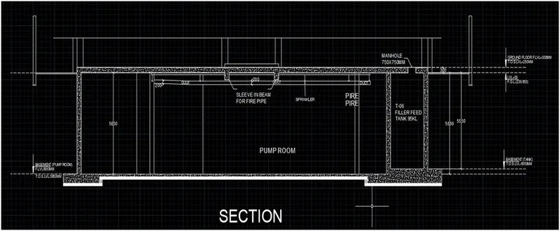
INTRODUCTION: Create the section view of an industrial building as given in Figure. Use hatches and dimensions wherever required. Also, provide annotations to the drawing.
PROCDURE:
1.Createa vertical line 5850mm
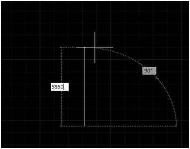
2.Offset 5313mm
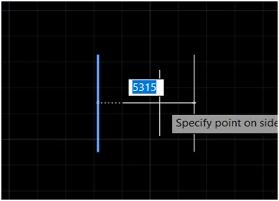
3.Again offset 5320mm
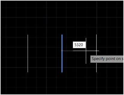
4.Again offset 3900mm, 4720mm, 1020mm, 5025mm, Then offset 150mm both side of the line as shown in figure .
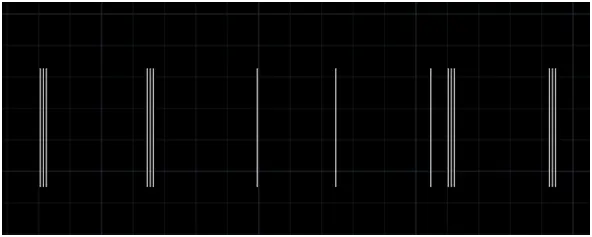
5.Again offset inner line inner side 3000mm, and 300mm as shown in figure
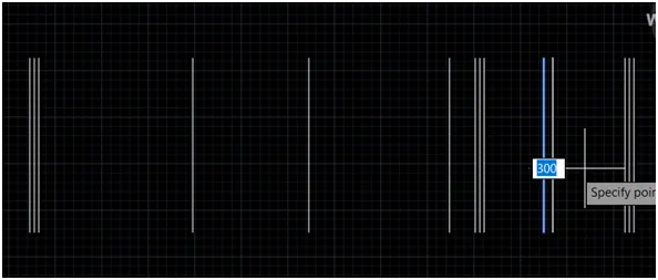
6.Then delete the mid selected line
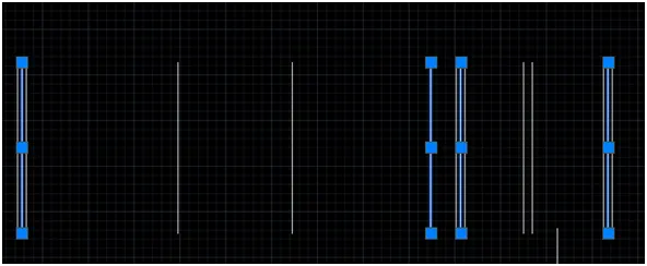
7.Join the bottom line
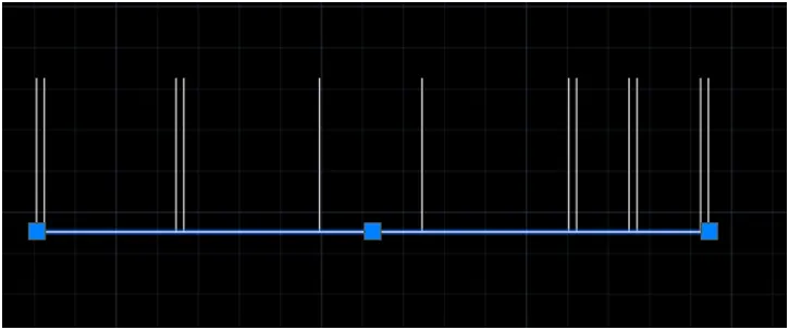
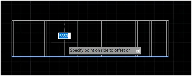
8.Offset 5850mm up side
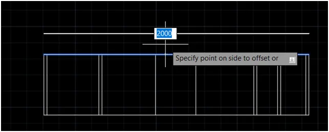
9.Offset 2000mm up side
10.Join a line of both side
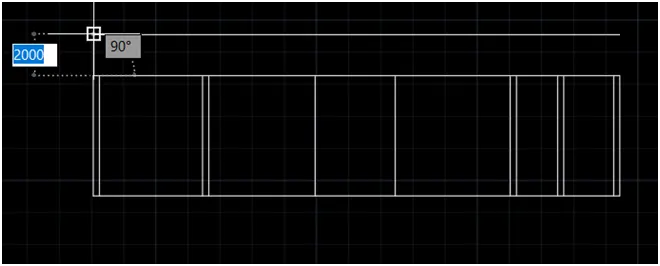
11.Offset the line 450mm at both side
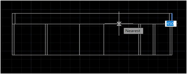
12.Then extend the line as shown in figure
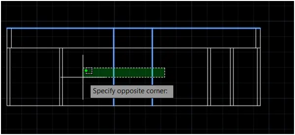
13.Then offset 225mm, both side
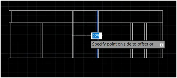
14.Then delete the mid line
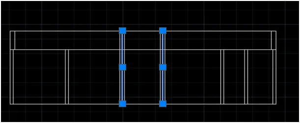
15.Then trim the bottom line
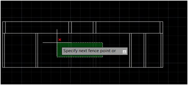
16.Then offset 300mm for slab thickness
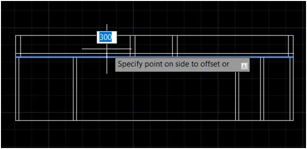
17.Then bottom side offset two times
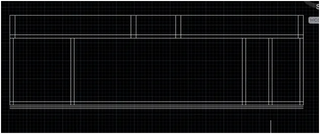
18.Then extend the line both outer line of bottom slab and join the line and short the mid line and join the bottom line
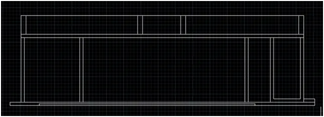
19.Then trim the bottom line as shown in figure
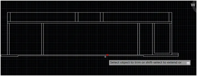
20.Then create a duct of the section as given figure
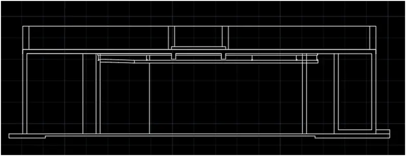
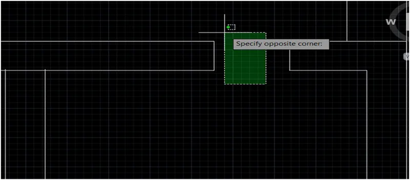
21.Then trim the man hole of this section
22.Then hatch the concreting portion
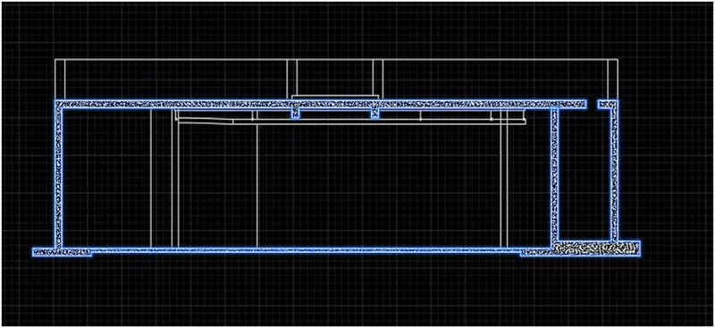
23.Then create a bottom surface and hatch as a solid surface
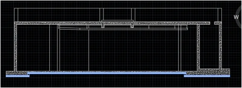
24.Then create side wall or side portion of the section as given figure
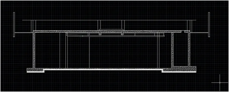
25.Then write the details of the drawing and dimension of the drawing and name of the drawing
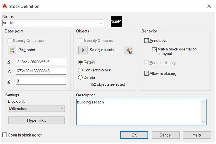
26.Then go for block command and give a name and select the pick point of the drawing and select the object and choose the unit of the drawing and annotative Then ok
RESULT: I am creating a section and their block as given in challanges.