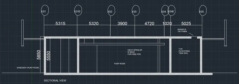
Creating Kitchen layout, Hatching of Architectural elements and sectional view of an Industrial Building in AutoCad
1)AIM:
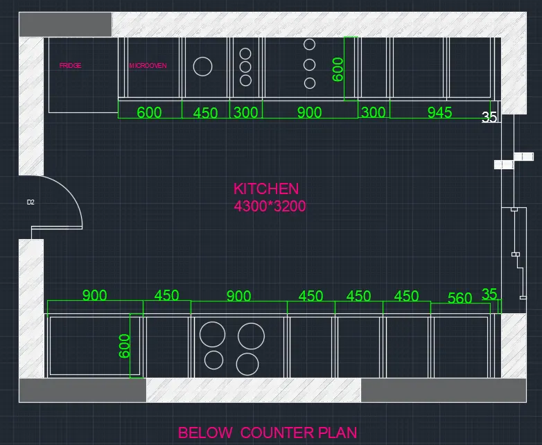
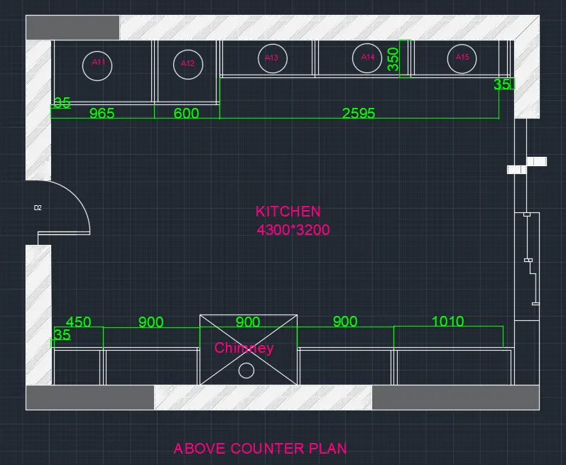
Create the layouts of the Kitchen and provide hatches pattern as shown. Also, use blocks wherever required. Provide appropriate dimensions in the plan. Assume the size of doors, appliances and others as per the standards.
PROCEDURE:
Create a rectangle of dimension 4300*3200
Using line,Trim,Arc,Circle the kitchen layout is created
Using Dimension style command the dimension of the kitchen layout created is mentioned.
The words are specified using Mtext command .
RESULT:
2)AIM:
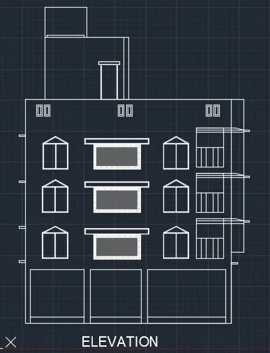
Create the elevation of the plan created in the Challenges 7 and apply proper hatch in the walls, doors, windows, and other architectural elements. Refer to the dimensions in Plans and sections in Challenges 7
PROCEDURE:
Elevation of walls ,doors ,windows & other structural elements is created using command XL(hor) & XL(ver)
Hatch are provided at required places
RESULT:
3)AIM:
Create the section view of an industrial building as shown in Figure. Provide appropriate hatches and dimensions wherever required. Also, provide annotations to the drawing.
PROCEDURE:
Using Line tool create wall of height 5550 & thickness 300
Create a industrial view using the given dimenison
Mention the dimension of each line usinng DIMSTYTLE command
Create a word using MTEXT command at required places
Using the HATCH command hatch the walls
RESULT: