Creating Kitchen layout, Hatching of Architectural elements and sectional view of an Industrial Building in AutoCad
CREATING KITCHEN LAYOUT, HATCHING OF ARCHITECTURAL ELEMENTS AND SECTIONAL VIEW OF AN INDUSTRIAL BUILDING
Introduction
The main tool used in this challenge is the hatch command.
Hatch: This command can be used to fill an enclosed area or selected objects with a hatch pattern. Follwing steps are involed in hatching an object:
- Click home tab--> Draw panel--> Hatch.
- On the properties panel--> Hatch type list, select the type of hatch needed.
- On the pattern panel, click a hatch pattern or fill.
- On the boundaries panel, specify how the pattern boundary is selected:
- Pick points: insertshatch or fill within a closed are that is bounded by one or more objects. Wth this method you click within the boundaries to specify the area.
- Select bounday objects: Insertsthe hatch or fill within a closed object, such as a circle, closed polyline or a set of objects with endpoints that touch and enclose an area.
- The selection methos is retained until you change it.
- Click an area or object to be hatched.
- On ribbon make any adjustments as needed:
- On the properties panel, you can change the hatch type and colours or modify the transperancy level, angle, or scale for the hatch.
- On the expanded options panel, you can change the draw order to specify whether the hatch and its boundaries are displayed in front of or behind other objects.
- Press enter to apply the hatch and then exit the command.
Various other commands used includes line, offset, copy, blocks etc.
1.
Aim:
To create the layout of the kitchen and provide appropriate hatch pattern. Also use proper dimension techniques to dimension the plan.
Procedure:
- Initially set the units as Decimal (mm).
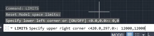
- Now, set the limits of the drawing:
- Specify the lower left corner: (0,0)
- Specify the upper right corner: (12000,12000)
- Below counter plan:
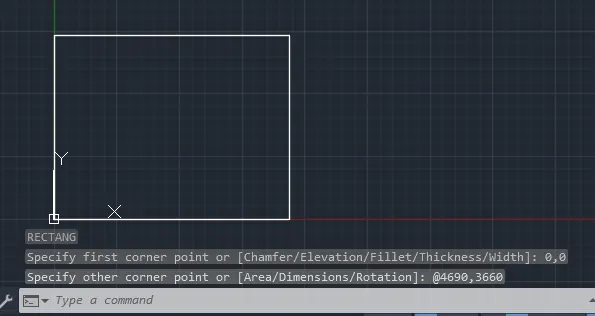
- First type rec in command prompt and create a rectangle of size 4690mmx3660mm.
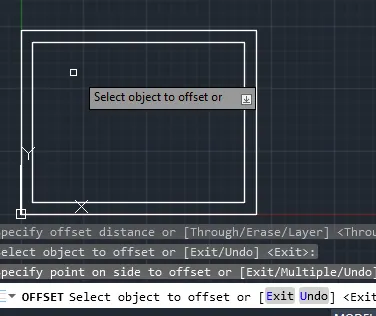
- Then create an offset of 230mm inwards to create the wall.
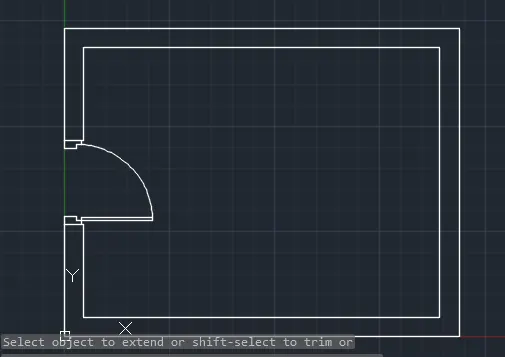
- Then, using the line command and circle command create the door for the kitchen.(Width is taken as 800mm)
- Then using line and offfset command create the cabinets for the kitchen.
- Type C to create circle
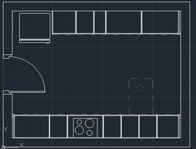
- Now, using the line, circle, offset trim commnd draw a sink.
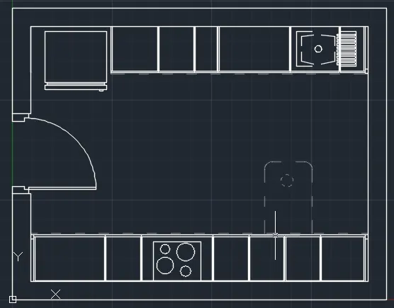
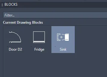
- Here, the sink, fridge and door are blocks.
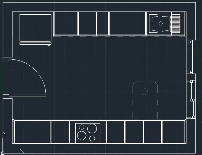
- Now, create the two windows on the right wall of the kitchen.
- Now, provide the necessary hatching to the walls.
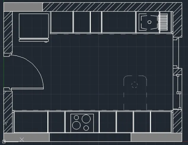
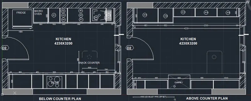
- Now, to complete the figure provide dimensions and necessary texts and annotations.
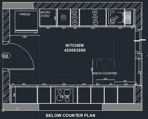
- This is the below counter plan.
- Now to create the above counter plan copy the above figure beside it and di necessary changes.
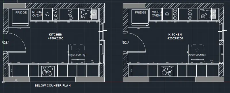
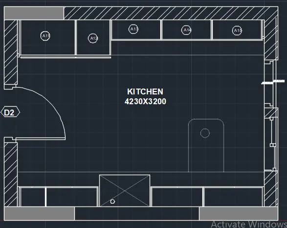
- Now, complete the figure by dimensioning it and providing necessary texts.
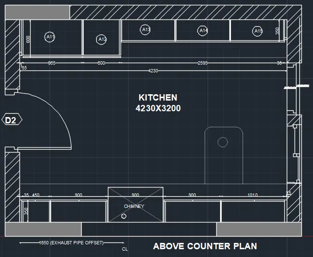
- Hence, the completed drawing is given below:
2.
Aim:
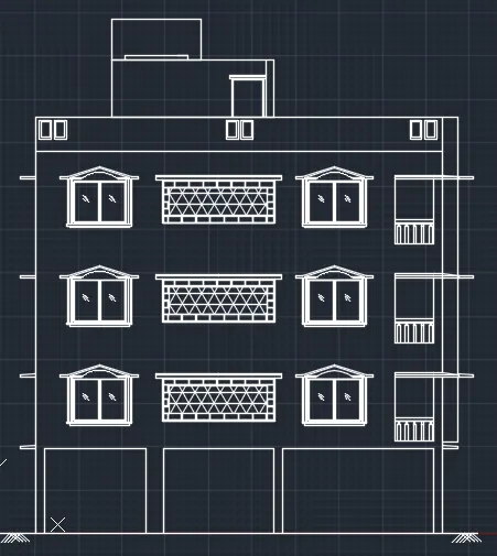
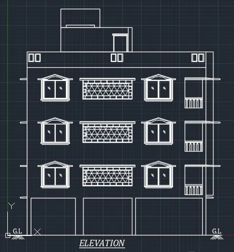
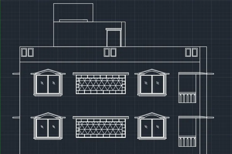
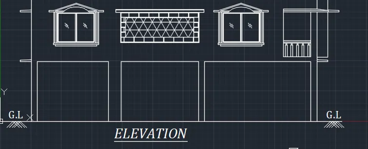
To create the elevation of the plan that was already created and to apply proper htch in the walls, doors,windows and other architectural elements.
Procedure:
- Initially set the units as Decimal (mm).
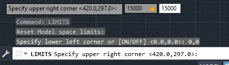
- Now, set the limits of the drawing:
- Specify the lower left corner: (0,0)
- Specify the upper right corner: (15000,15000)
- Using line command initially draw the outline of the structure refering to the challenge 7 plan.
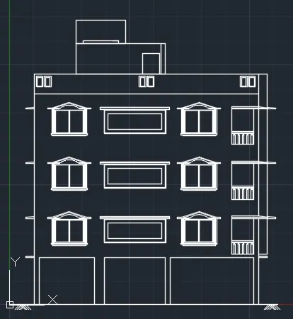
- Now, provide the necessary hatching as per the requirement.
- Provide the necessaay texts.
3.
Aim:
To create the section view of an industrial building and provide appropriate hatching and dimensions as required and also provide annotations to the drawing.
Procedure:
- Initially set the units as Decimal (mm).
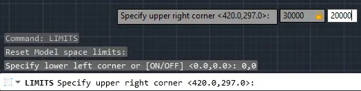
- Now, set the limits of the drawing:
- Specify the lower left corner: (0,0)
- Specify the upper right corner: (30000,20000)
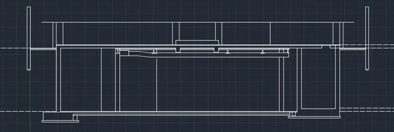
- Use line command to create the outline of industrial building.
- Offset command can be used to offset the lines wherever required.
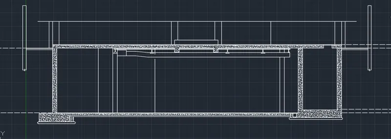
- Now, provide necessary hatching (AR.CONC)in the drawing.
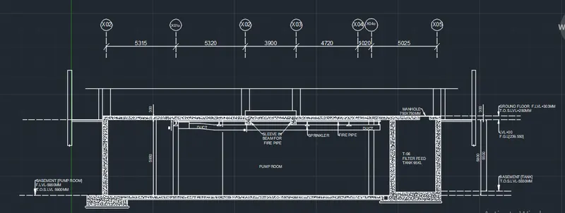
- Now, using the command MT provide necessary text and dimensions.
- Use command C to draw circle.
Result:
1. The layout of the kitchen drawing created is as follows: Both below and above counter plan
2.The elevation of the plan given in challenge 7 is created as given below:
3. The section view of an industrial building created is given below: