Creating Conceptual mass in REVIT and Creation of Sinusoidal curve and a Parametric stadium using Dynamo
1) CREATING SINUSOIDAL POINTS, CYRAVE AND SURFACE
Creating the sinusoidal points
- Open a new architectural file in Revit.
- Go to the manage tab and open dynamo.
- Open a new file in dynamo.
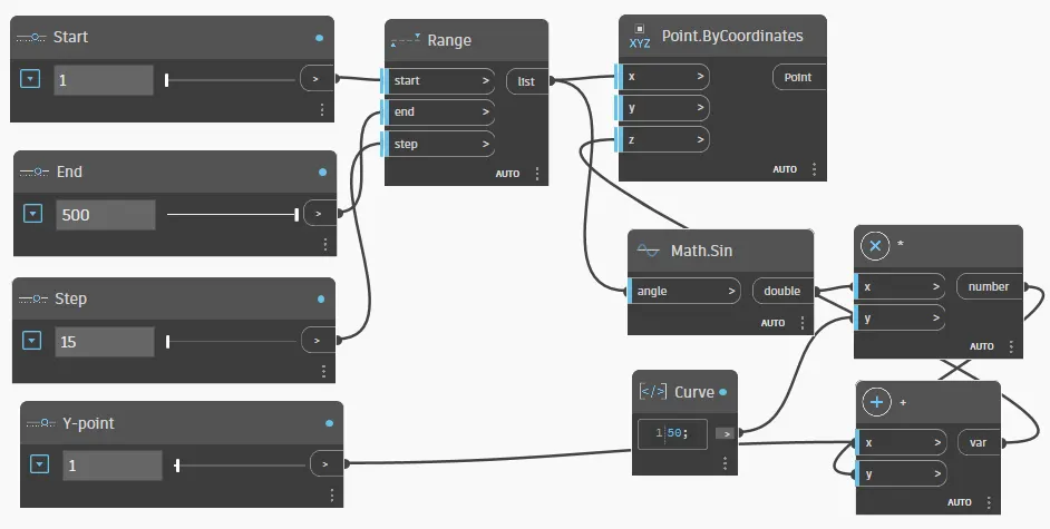
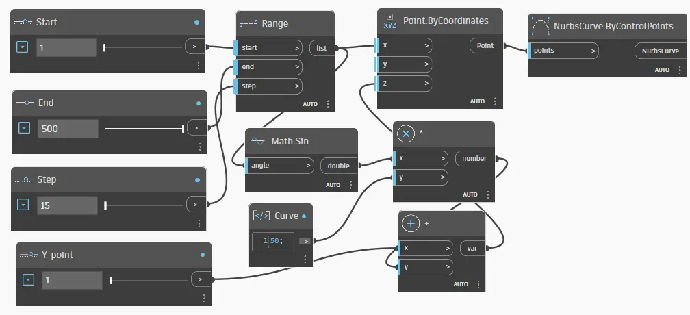
- From library, insert three integer sliders and rename as start, end and step.
- Then insert range block and connect the integer sliders as input.
- Insert a block of Point.ByCoordinate. Then connect the output of range block to the 'x' of the Point.ByCoordinate block.
- Add a code block and rename it as curve. Enter a value of 50.
- Then insert Math.Sin block. To this, connect the range as input.
- Then insert the mathematical operation of multiplication, '*'.
- Now, connect the Math.Sin block as input for 'x' and code block named as curve, ass input for 'y' in the product block.
- Now insert another integer slider and rename it as Y-Point.
- Add a block of the mathematical operation addition, '+'.
- In this block, connect the output from product block to 'y' and the integer slider named as Y-Point to 'x'.
- Connect the output of addition block to the 'y' in the Point.Bycoordinate block.
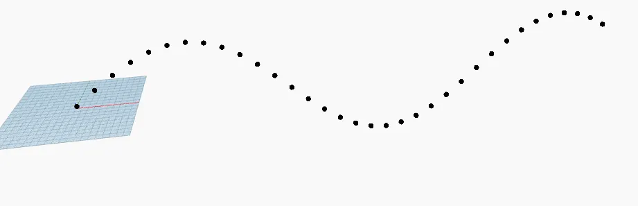
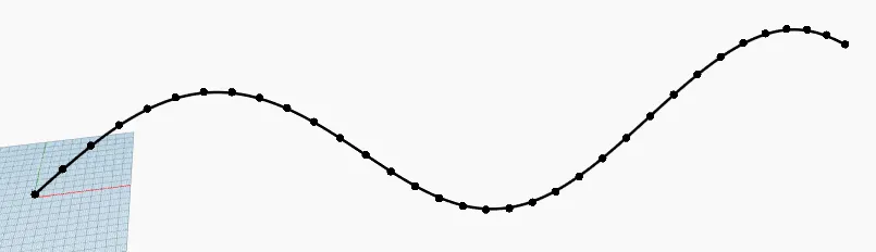
- We can see the sinusoidal points created.
Creating sinusoidal curve
- Insert a block of NurbsCurve.ByControlPoints.
- Connect output from the Point.ByCoordinate block to the block of NurbsCurve.ByControlPoints.
- Upon connecting the blocks, we can see the sinusoidal curve getting created.
Creating surface from curve
- Select all output nodes.
- Then go to edit and click on create custom node.
- Give the name as SinWave, description as Sin wave curve and category as Analyze and click save.
- Now copy all the entities and paste it for two times, so as to create two more curves.
- Change the value of Y-points to see three sinsusoidal curves.
- Now insert a block of list items and connect the blocks of sinwaves to it.
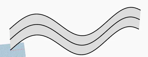
- Then insert a block of Surface.Byloft and connect the list block to it, so as to create surface from the curve.
- We can see that the surface is generated from the curves.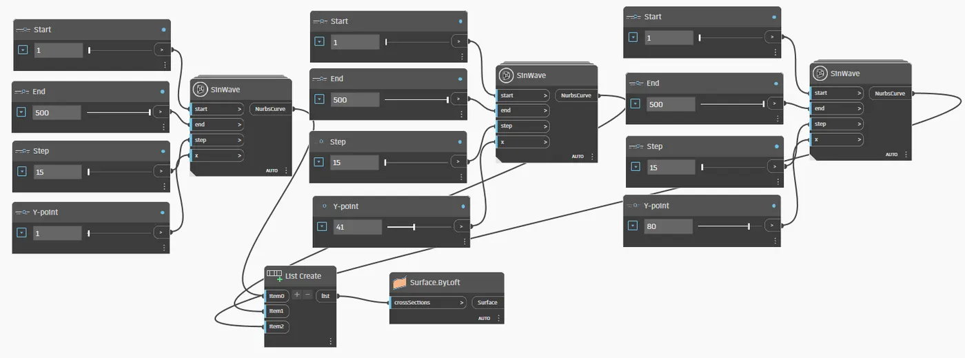
2) CONCEPTUAL FLOOR PLAN LAYOUT IN DYNAMO
- Open a new architectural template.
- Go to the manage tab and open Dynamo.
- In dynamo, open a new file and save it.
- From library, add two integer sliders and rename it as x and y.
- Then add four blocks of Point.ByCoordinates and rename it as Origin(0,0,0), Control Point 1(x,0,0), Control Point 2(0,y,0) and Control Point 3(x,y,0).
- Connect the sliders to the x and y in respective blocks where x and y values are not zero.
- We can see that four points are created.
- Now insert four line blocks by start end points.
- For these line blocks, provide inputs from the Point.ByCoordinate blocks.
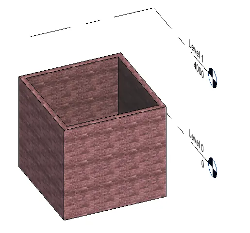
- After connecting these, we can see a rectangle shape created. This is a conceptual floor layout.
- Now add a block of Wall.ByCurveAndHeight.
- This block has four parameters; curve, height, level, wall type.
- We have to provide input for all these parameters.
- For that, add a block of list and connect four line blocks to it.
- Insert a number slider for giving the height of the wall.
- Add a block of level and from the drop down in the block, select the level 0, where the wall is to be placed.
- Now add the block for wall type and select the type of wall from the drop down.
- Then connect all the parameters to the block of Wall.ByCurveAndHeight.
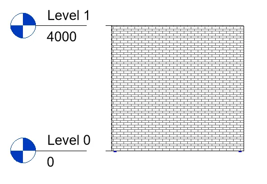
- Go to the Revit screen, we can see that the wall is created.
3) TO CREATE AN ARRAY OF COLUMNS
- Open a new architectural template in Revit.
- Go to the architectural tab.
- From the ribbon, select architectural columns.
- From the property palatte, select the type of column.
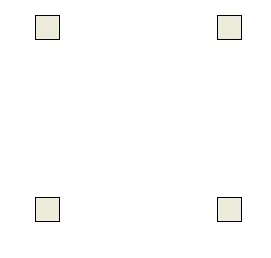
- Draw four columns.
- Then go to the manage tab.
- Click on dynamo.
- When dynamo opens, click on new to open a new file in dynamo.
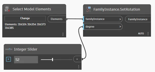
- Then add a block of select model elements.
- Click on select in the box, and then go to the Revit screen.
- Select all the four columns.
- Then go to he dynamo, we can see this items in the block added.
- Now add a block of set rotation.
- We have to assign value for degree in this block. For that, add an number slider.
- Now, connect the first block to family instance and the number slider to degree.
- Go to the Revit screen. We can see that the columns are rotated.
- We can adjust the degree of rotation using the number slider.
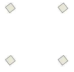
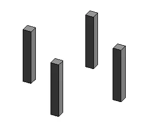
4) TO CREATE CONCEPTUAL MASS IN REVIT
- Open Revit software.
- Open a new Revit family.
- Click on conceptual mass and then on metric mass.
- Open the North elevation.
- Go to create, click on levels. Create another level at an offset of 3000mm and name it as 'Height of roof'.
- Then open the floor plan for roof. Then go to set option in the modify tab and set the workplane.
- Now, from the draw option, select spline to create a curve for the parametric structure.
- Go to the 3D view and see the curve created.
- Click on the control point in the left end of the spline.
- Then click on set and then click on show in the workplane in the ribbon.
- Select circumscribed polygon from draw. Set the number of sides as 4 and radius 3000mm.
- Repeat the same steps for all the control points in the spline.
- Select the spline and the polygons, then click on create form in the ribbon.
- Select all the planes and the curve. Uncheck all planes and click OK.
- Click on divide surface. Then in the property palattee, select triangle bent from the drop down.
- Enter the U grid fixed number as 70 and the V grid fixed number as 10.
- Now go to the file tab, click on new and family, open metric curtain panel pattern based. Then when the pattern appears, go to the property palattee and select the type as triangle bent.
- Now, in the left end of the ribbon, click on reference, select points from draw, and click on draw on face. Then click on the midpoint of control points 1 and 2. Then click on set option. Select circle from the draw and draw circle of radius 75mm at the midpoint.
- Now select the circle and triangles and click on create form. Then click on load into family.
- Open the 3D view, select all the entites, uncheck all other than form.
- From the property palattee, assign the pattern as family 2.
- It will take sometime for the run. Afterwards which, we can see that the pattern is assigned.
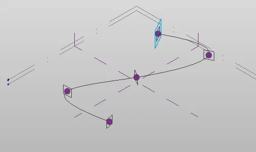
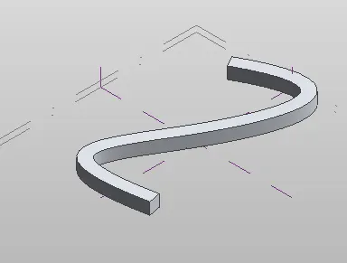
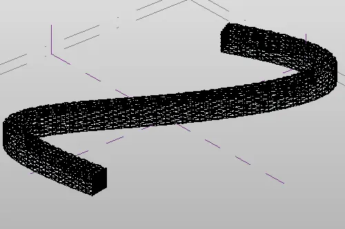
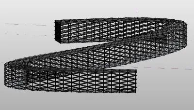
5) TO CREATE A PARAMETRIC STADIUM USING DYNAMO
- Open a new architectural template and save it.
- Go to manage tab, open dynamo and open a new file in dynamo.
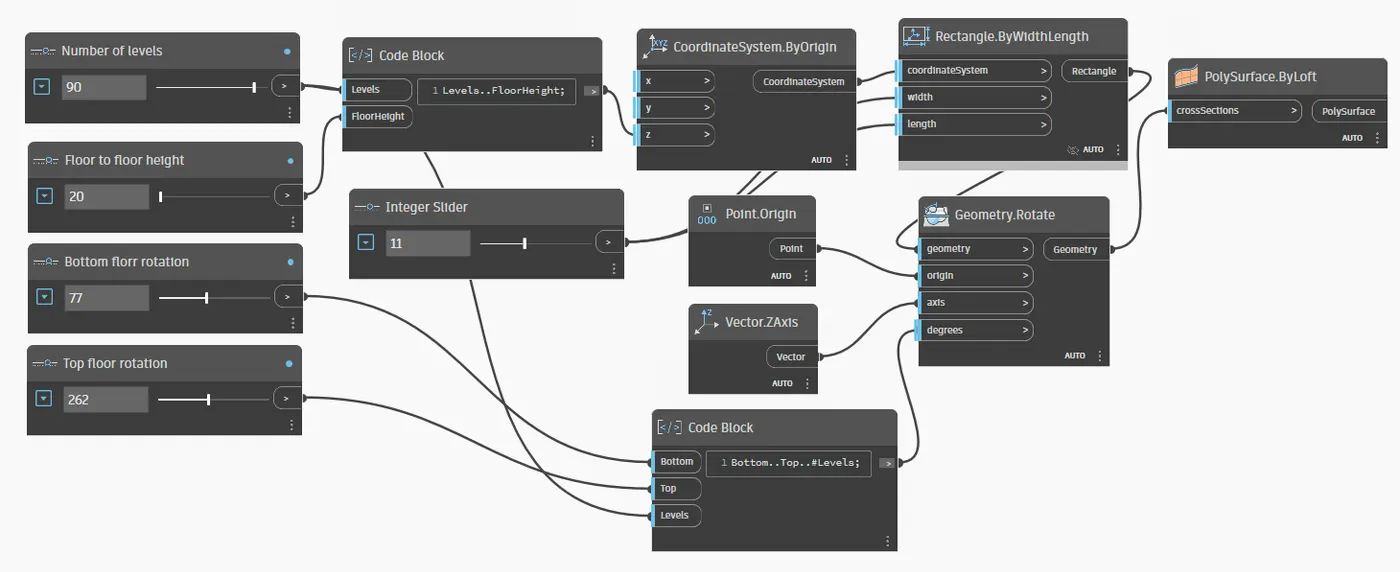
- Add four integer slider blocks and rename it as ; Number of levels, Floor to floor height, Bottom floor rotation, Top floor rotation.
- Add a code block and enter parameters as levels and floor height.
- Connect the integer sliders of level and floor height to the newly added block.
- Add a block of coordinate system by origin and connect the code block we added to the z of the coordinate system block.
- Add blocks of rectangle by width and length with coordinate system.
- Add two integer slider blocks for width and length. Connect the coordinate system blocks and the integer sliders added now to the rectangle block.
- Now add a block of polysurface by loft. Connect the rectangle block to this block.
- Add a block of geometry rotate, for which, the input for geometry is the rectangle block.
- To input origin value, add an integer slider.
- Then add z axis vector block. Then add a code block and enter parameters for rotation. Connect the integer sliders we created at the first step to this block.
- Connect parameters to the geometry rotate block.
- Connect the output from the geometry block to polysurface crosssection block.
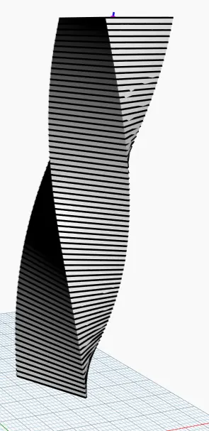
- Now check the parametric structure created.