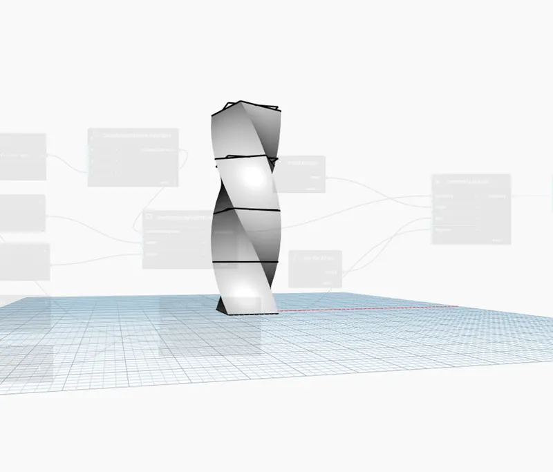
Creating Conceptual mass in REVIT and Creation of Sinusoidal curve and a Parametric stadium using Dynamo
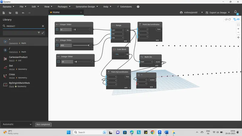
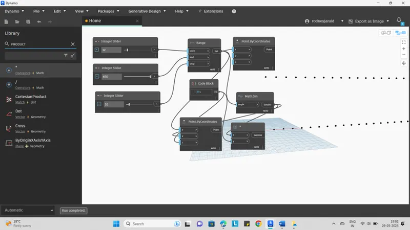
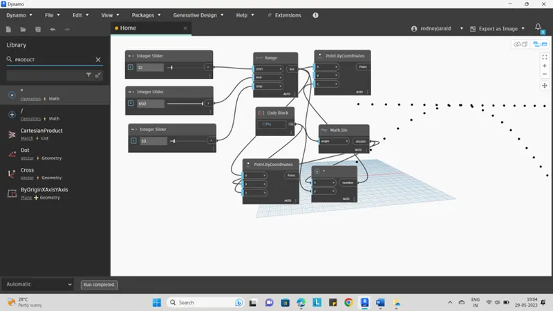
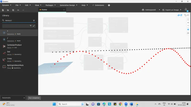
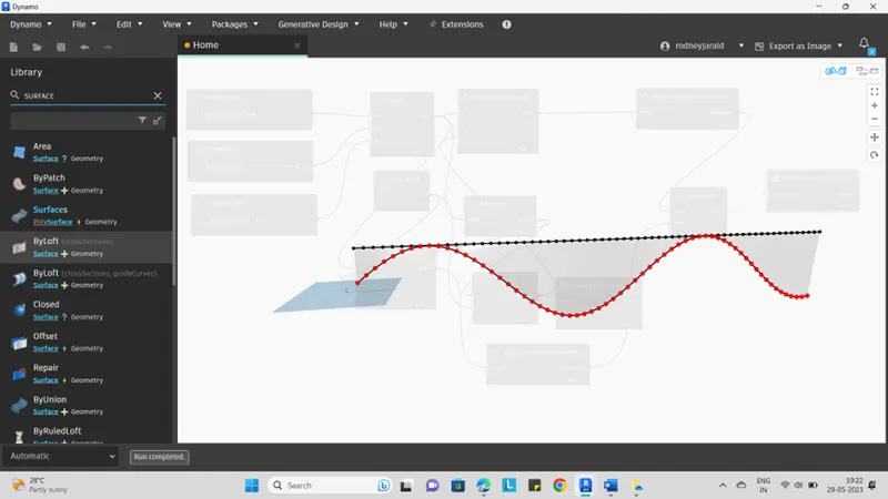
1 .Using Dynamo create a set of sinusoidal points and create a curve and create a surface out of the curve.
AIM :
To create a set of sinusoidal points and create a curve and create a surface out of the curve.
PROCEDURE :
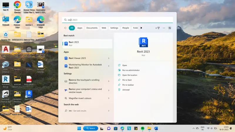
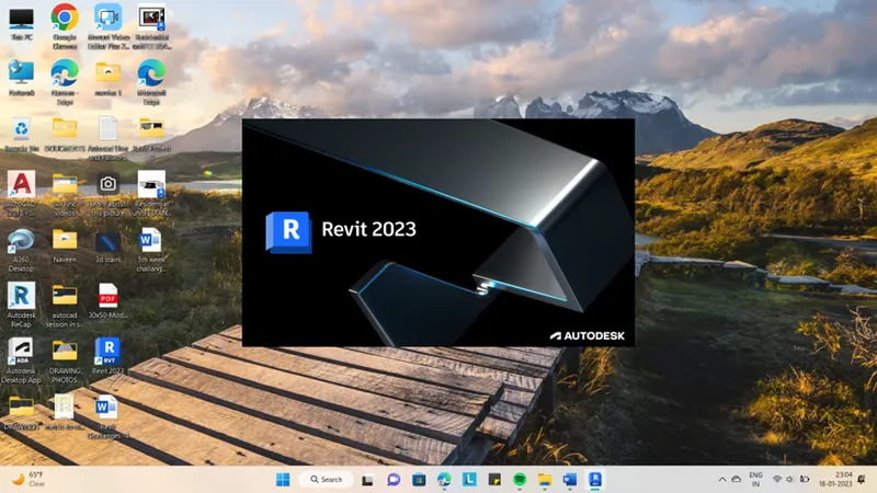
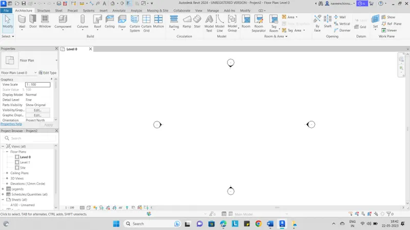
- Open “REVIT 2024” software
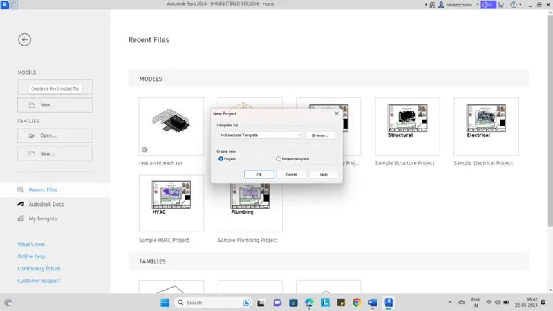
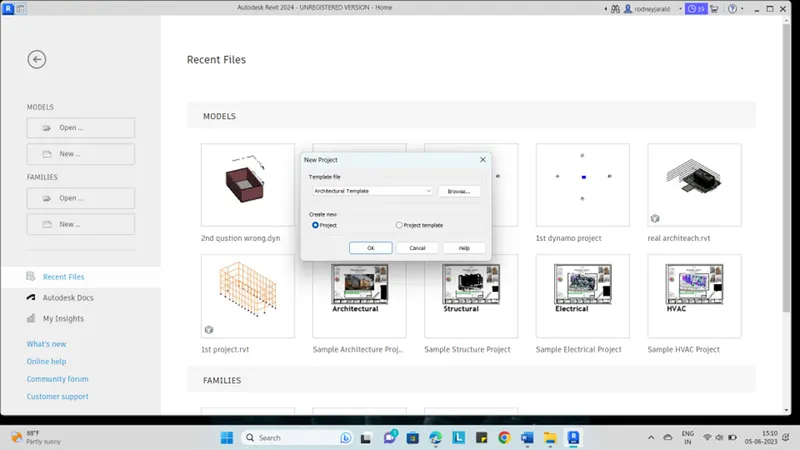
- Go to the “NEW PROJECT “
- Select the “ARCHITECUTE TEMPLATE”
- U will get one “NEW PAGE”
- Than Go to the ”MANAGE TAP”
- There is option called “DYNAMO”
- Click the “DYNAMO” option
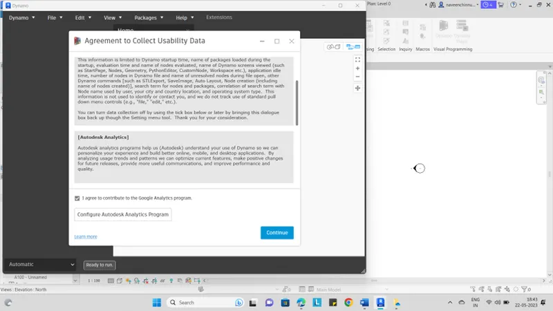
- Once you clicked u will get dialog box called “AGGREMENT TO COLLECT USABILITY DATA”
- Click “CONTINUE”
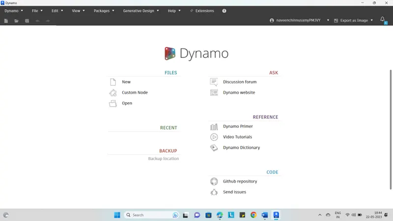
- Then u will get dynamo dashboard
- Select “NEW” option
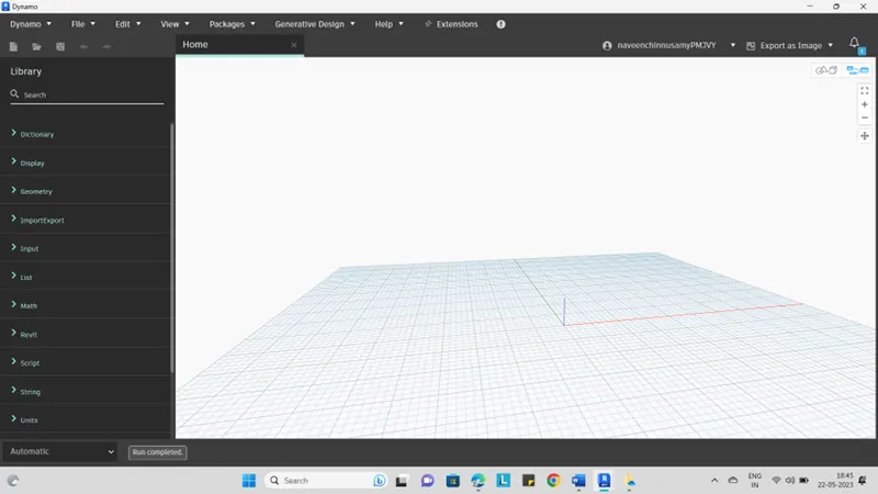
- Than u will get “NEW WINDOW “
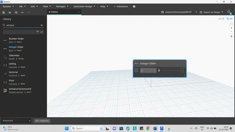
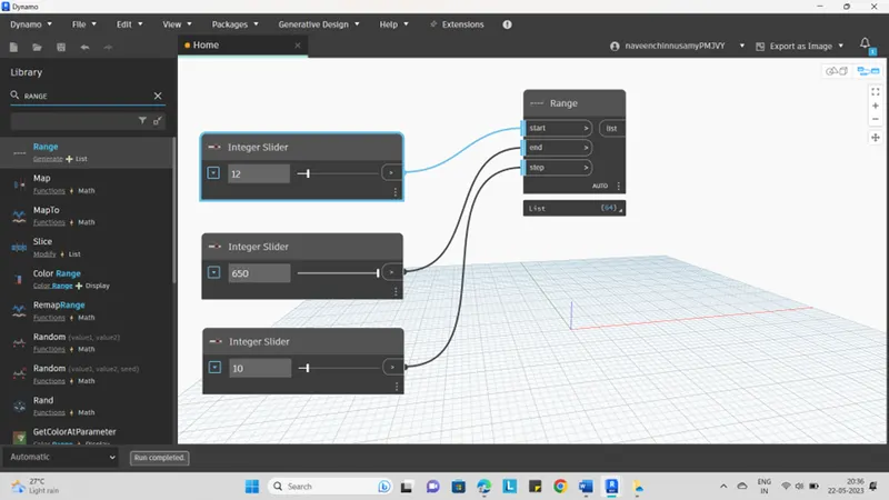
- Than go to the “search” Option and
- Type “INTEGEAR SLIDER”
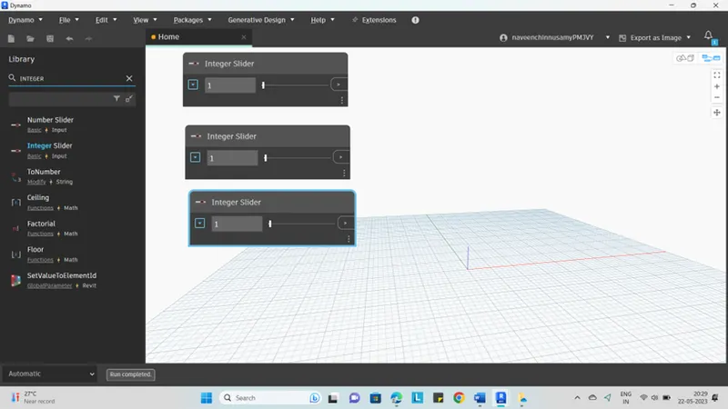
- Than “copy” and past it two time
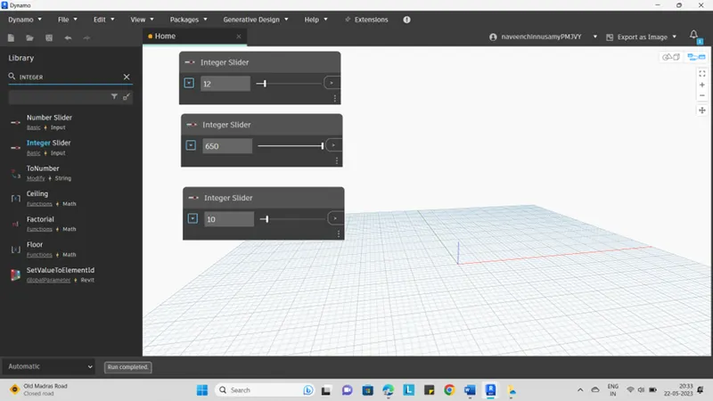
- Than increase the number each “INTEGER SLIDER” as per the answer
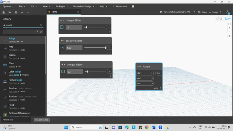
- Than type “RANGE “ option from the search box .
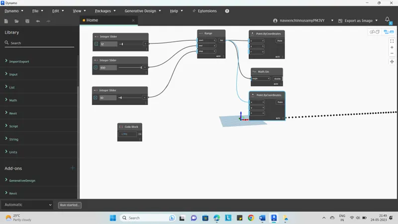
- Than connect the “INTEGEAR SLIDER” to “RANGE “
- Like first as “START” , second one as ”END” , third one as “STEP”
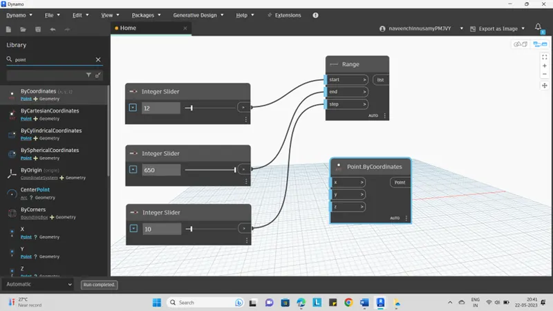
- Go to the “SEARCH” box
- Type “POINT BY COORDINATES”
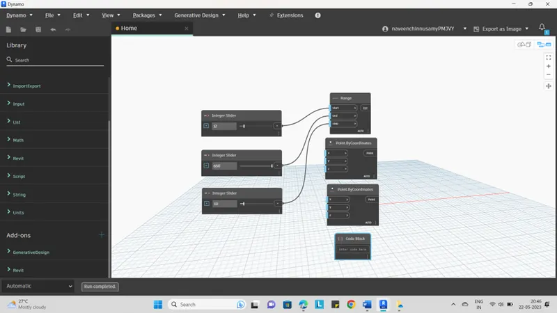
- Then we need to one more “POINT BY COORDINATES” click “CTRL+C” and “CTRL+V” option
- Than Go to the “SEARCH” box
- Type “CODE BLOCK”
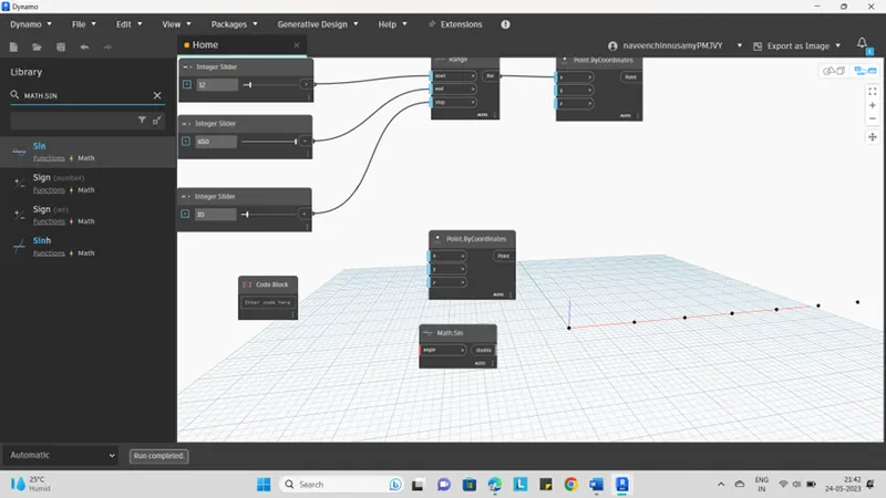
- Than Go to the “SEARCH” box
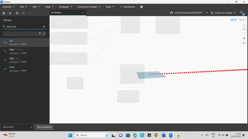
- Type “MATH.SIN”
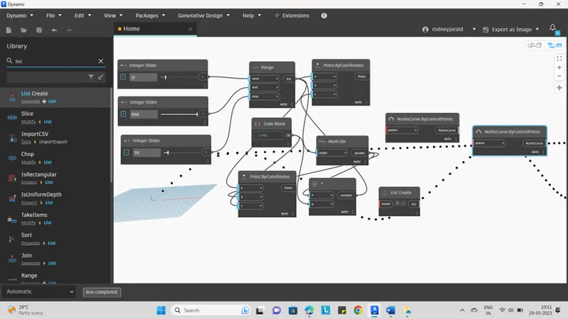
- Than connect the “RANGE “ to “PIONT.BY COORDINATES “
- than u will get the “POINTS” first
- provide the “CODE BLOCK” as “50”
- than connect “RANGE” with “MATH.SIN”
- we need to connect “RANGE “ with second “POINT.BY COORDINATES”
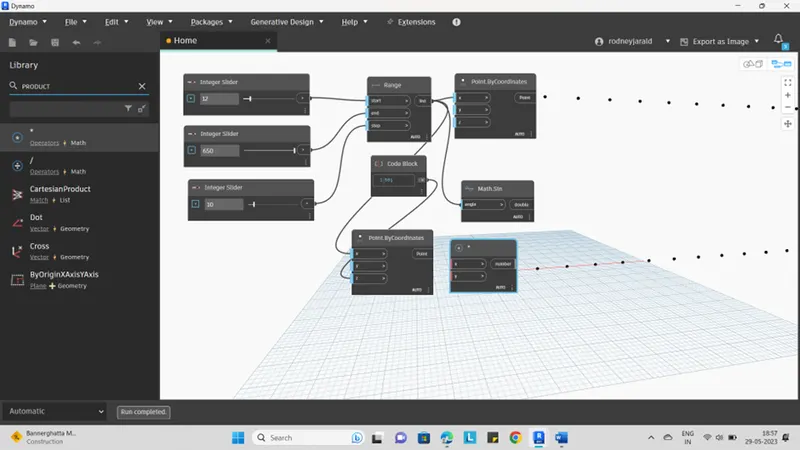
- Go to “SEARCH BOX” type “PRODUCT”
- Next step is connect “CODE BLOCK” with “Z” which is second “POINT.BY COORDINATES”
- Than connect the “MATH.SIN” to “POINT.BY COORDINATES” in “Y”
- Than connect “MATH.SIN” to “PRODUCT X”
- Than CONNECT “CODE BLOCK” to “PRODUCT Y”
- Than “PRODUCT VARIOUND “ to “POINT BY COODRINATE “ in “Z”
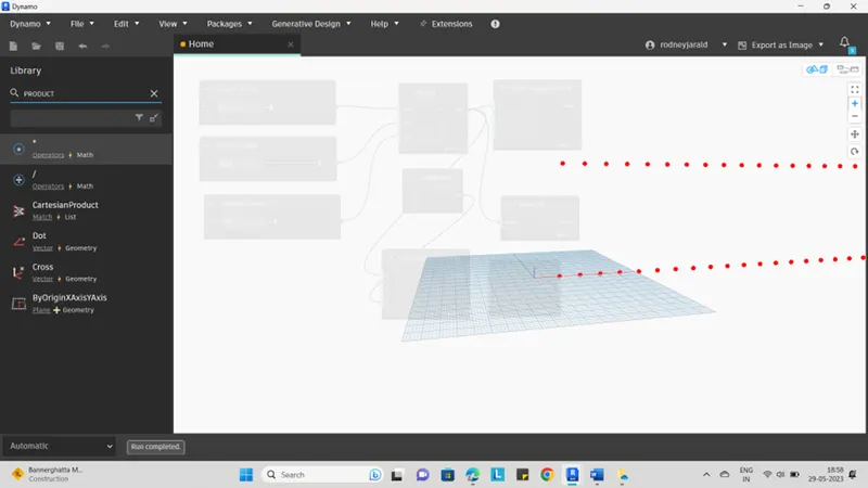
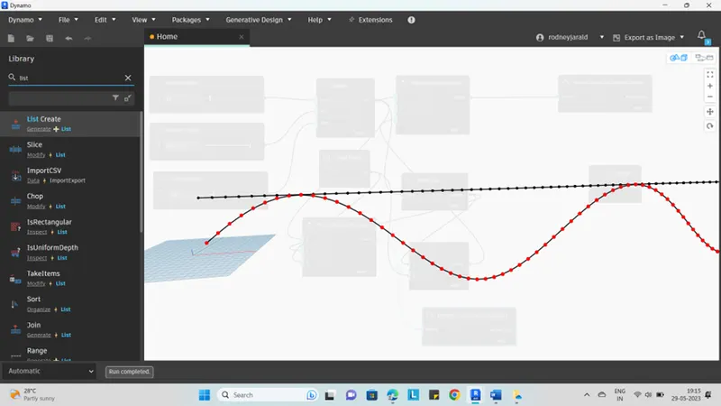
- u will get “CURVE”
- Go to “SEARCH” option
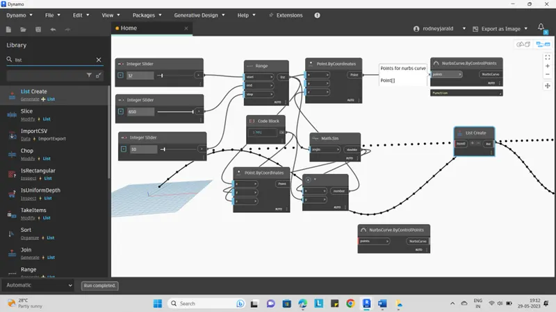
- Type “NURBS BY CONTROL POINT “
- Go to “SEARCH “ option
- Type “LIST” option
- Than select “ NURBS BY CONTROL POINT”
- Just “COPY” and “PAST”
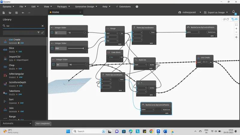
- connect “POINT BY COORDINATE” to “ NURBS BY CONTROL POINT”
- u will get line in the curve
- similarly connect another “POINT BY COORDINATE” to “ NURBS BY CONTROL POINT”
- u will get line in the curve
- Go to the “LIST” option
- Click “+” u will get one more “ITEM”
- Just connect both “ NURBS BY CONTROL POINT” to “ITEM” one and two
- Go to “SEARCH “ option
- Type “SURFACE BY LOFT CROSS SECTION”
- And connect the “LIST “ to “SURFACE BY LOFT CROSS SECTION”
- Finally show the result
RESULT :
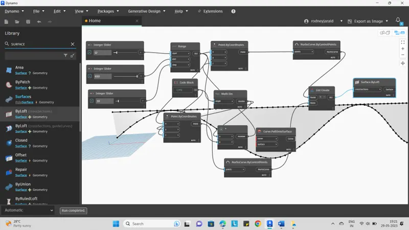
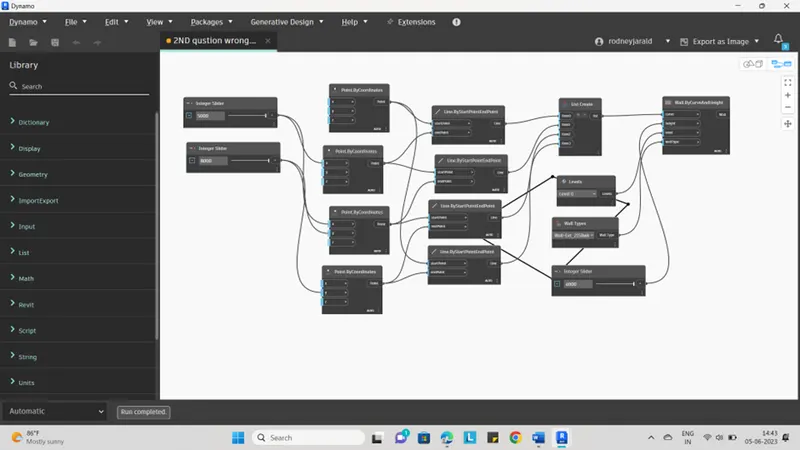
2.Create a conceptual layout of floor plan in dynamo . Using the tools available in dynamo link the lines to appropriate model elements in Revit by choosing the wall types and wall parameters. Make use of the sliders to slide through the height of the wall and length of the wall.
AIM :
To Create a conceptual layout of floor plan in dynamo
PROCEDURE :
- Open “REVIT 2024” software
- Go to the “NEW PROJECT “
- Select the “ARCHITECUTE TEMPLATE”
- U will get one “NEW PAGE”
- Than Go to the ”MANAGE TAP”
- There is option called “DYNAMO”
- Click the “DYNAMO” option
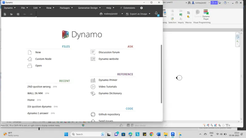
- Then u will get dynamo dashboard
- Select “NEW” option
- Than u will get “NEW WINDOW “
- Than go to the “search” Option and
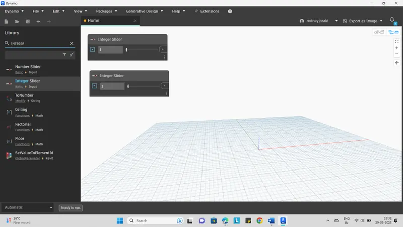
- Type “INTEGEAR SLIDER”
- Than “copy” and past it one time
- Than increase the number as “100”each “INTEGER SLIDER” as per the answer
- Go to “SEARCH” box
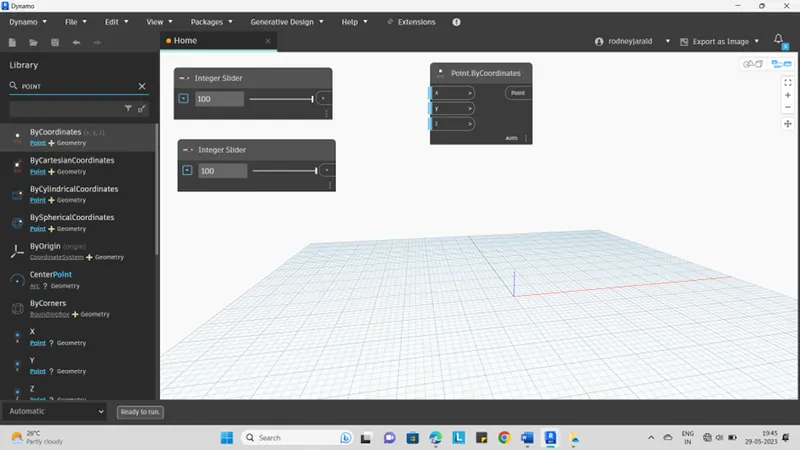
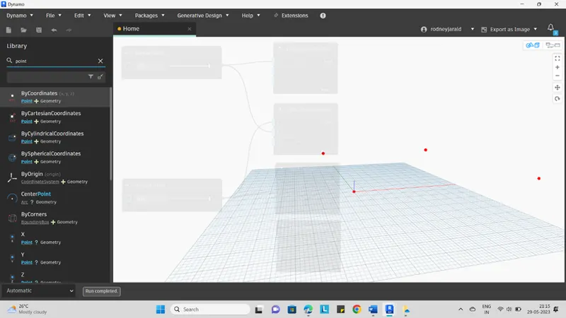
- Type “POINT.BY COORDINATES”
- Select “POINT.BY COORDINATES”
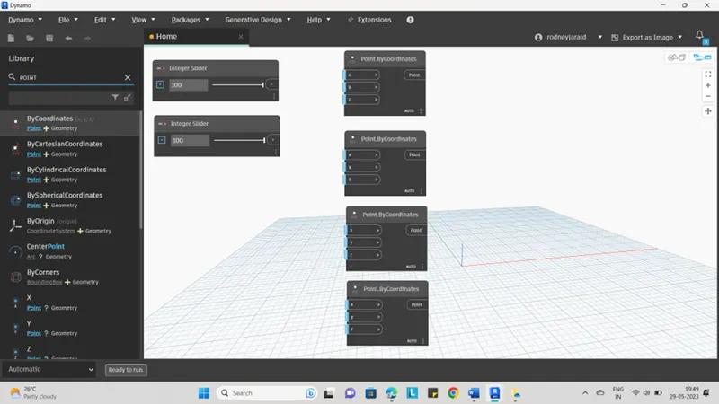
- Copy and past it three time .
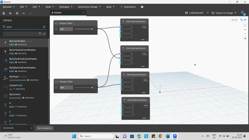
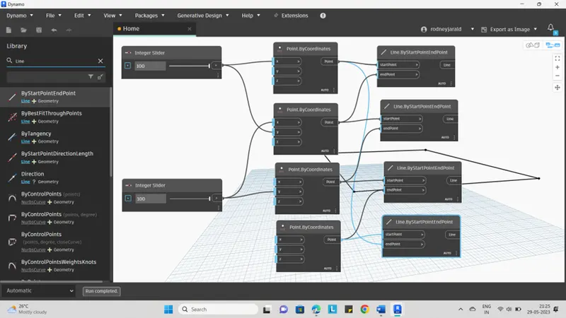
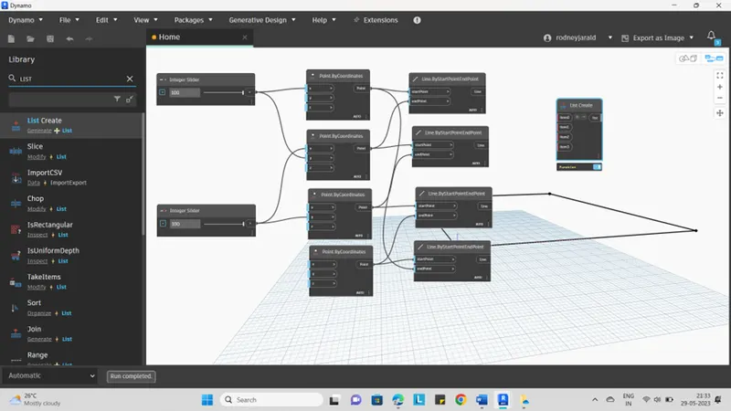
- Than connect with 1st “INTEGER SILDER “ to “1STBY COORDINATE “ in “X”
- Than connect with 1st “INTEGER SILDER “ to “1STBY COORDINATE “ in “Y”
- Same as connect with 2nd “INTEGER SILDER “ to “2ndBY COORDINATE “ in “X”
- connect with 2nd “INTEGER SILDER “ to “3RDBY COORDINATE “ in “Y”
- Go to the “SEARCH” option
- Type “LINE” option
- Select the “LINE.BY START POINT END POINT “
- Copy and past it in three time
- Connect “1ST POINT .BY COORDINATES” to “1st LINE START POINT “
- Connect “2nd POINT .BY COORDINATES” to “1st LINE END POINT “
- Connect “1ST POINT .BY COORDINATES” to “4th LINE END POINT “
- Connect “2ND POINT .BY COORDINATES” to “2ND LINE START POINT “
- Connect “3RD POINT .BY COORDINATES” to “2ND LINE END POINT “
- Connect “3RD POINT .BY COORDINATES” to “3RD LINE START POINT “
- Connect “4TH POINT .BY COORDINATES” to “3RD LINE END POINT “
- Connect “4TH POINT .BY COORDINATES” to “4TH LINE START POINT “
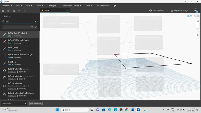
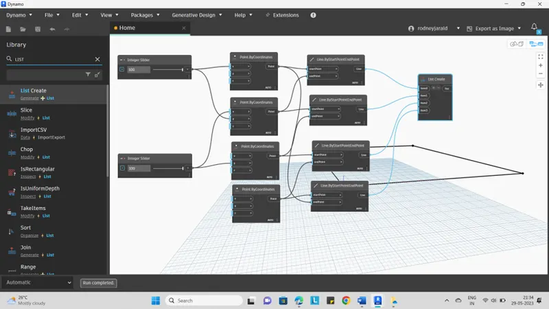
- Till now we created the wall
- Go to “SEARCH” option
- Type “ LIST”
- In the “LIST” add “3 MORE ITEM”
- Than connect the “LINE.BY START POINT END POINT “ to “LIST ITEM 0,1,2,3”
- Go to “SEARCH” box
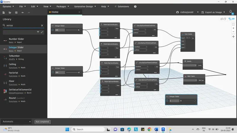
- Type “LEVELS” and “WALL TYPE” and “INTEGER SLIDER”
- Select “LEVEL 1”
- Wall type as “WALL -EXT_215WK”
- “INTEGER SLIDER AS 10”
- Go to “SEARCH” option
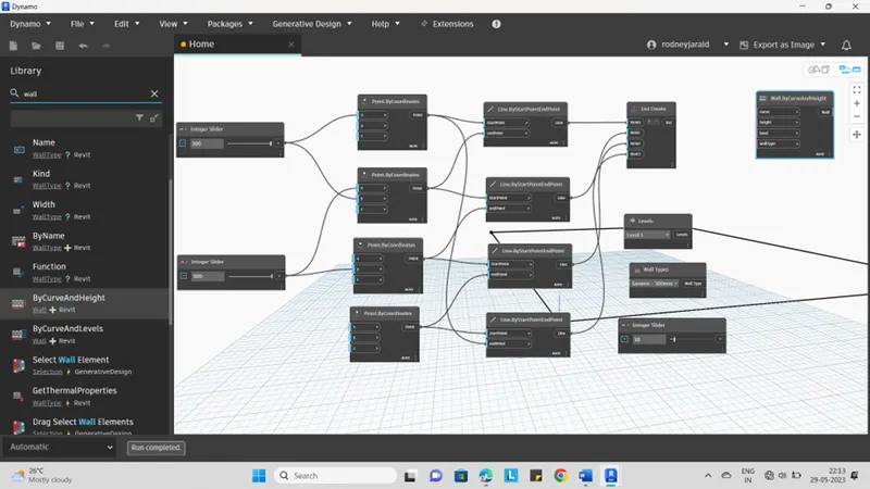
- Type “WALL BY CURVE AND HEGHT “ option
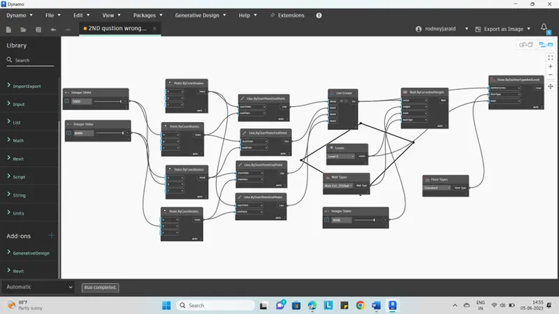
- Connect with “LIST” to “CURVE”
- Connect with “LEVELS” to “LEVELS”
- Connect with “WALL TYPES” to “WALL TYPE”
- Connect with “INTEGER SLIDER” to “HEIGHT”
- Till now we created the wall
- Go to dynamo
- Search ‘FLOOR TYPE “ option
- and Type “FLOOR BY LEVEL OUTLINE CUVRUE”
- than connect with “LIST” to “OUTLINE CURVES”
- connect with “FLOOR TYPES to “FLOOR TYPE”
- Connect with “LEVELS to LEVEL “ option
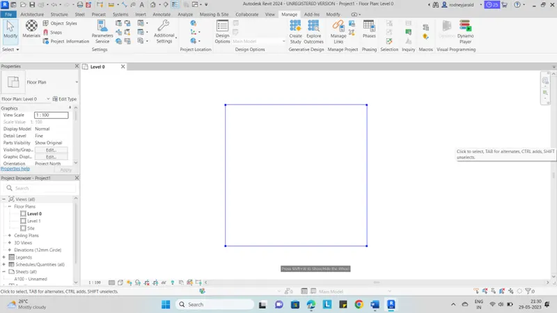
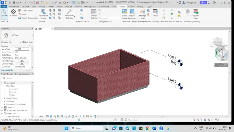
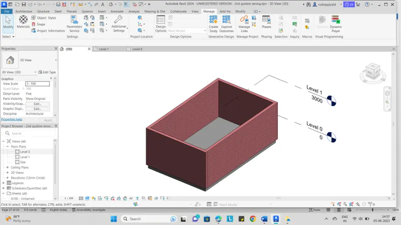
- Than go to the “REVIT “ Check the Drawing
- Finally show the “RESULT”
RESULT :
3.Create an array of model elements in Revit. Use dynamo to vary the properties of model elements by using the slider or code block
AIM :
TO Create an array of model elements in Revit
PROCEDURE :
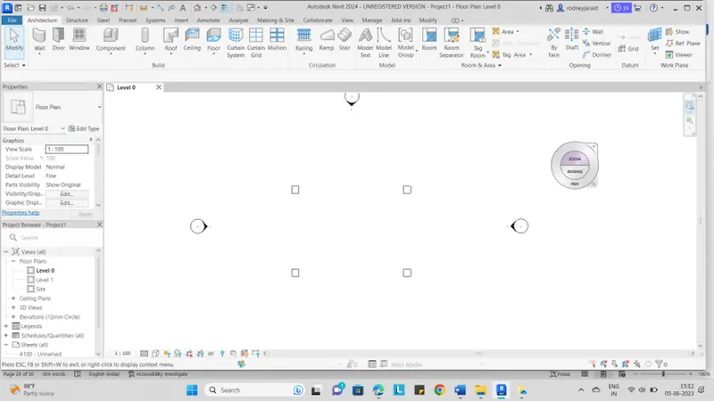
- Open “REVIT 2024” software
- Go to the “NEW PROJECT “
- Select the “ARCHITECUTRE TEMPLATE”
- Once open the page
- Go to “ARCHITECUTRE TEMPLATE”
- Go to the “Columns”
- Create “ARCHITECUTRE COLUMNS”
- Than Go to the ”MANAGE TAP”
- There is option called “DYNAMO”
- Click the “DYNAMO” option
- Then u will get dynamo dashboard
- Select “NEW” option
- Than u will get “NEW WINDOW “
- Than go to the “search” Option and
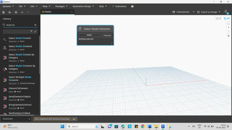
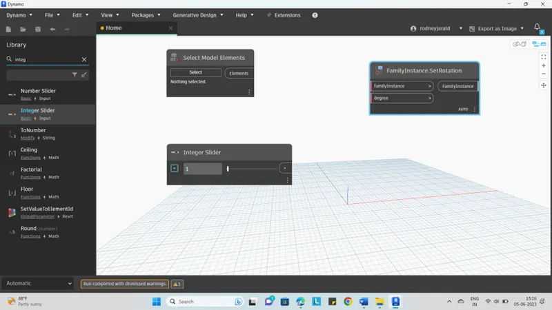
- Type “SELECT MODEL ELEMENT “ choose “MULTIBLE ELEMENT “
- Than go to the “search” Option and
- Type “SET BY ROATATION “ option
- Than go to the “search” Option and
- Type “INTEGER SLIDER “
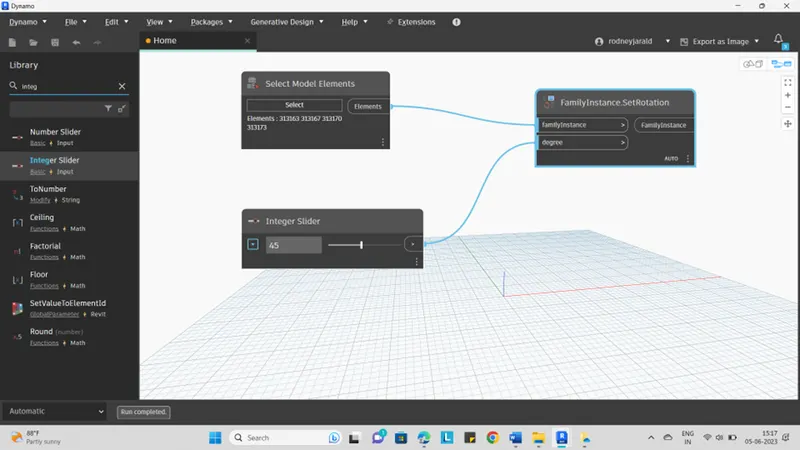
- Click the “SELECT” option and Select all the columns
- Choose the rotation angle is “45”
- Than connect “SELECT MODEL ELEMENT TO FAMILY INSTACE”
- Same like connect “INTEGER SLIDER TO DEGREE”
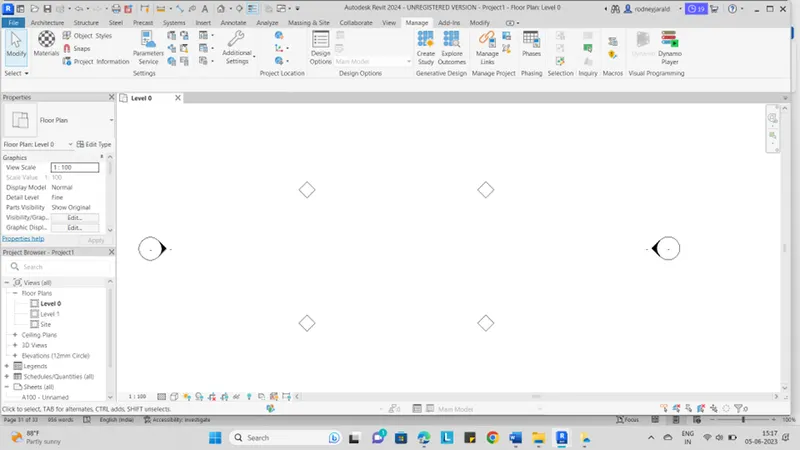
- Than cross check in Revit and finally show the Result
RESULT :
4. Create a conceptual mass in Revit and develop a parametric column by dividing the surfaces and apply the concepts similar to used in parametric walkway modelling. Use triangular bent or square shaped panels to add finish to the parametric column
AIM :
To create a conceptual mass in Revit and develop a parametric column by dividing the surfaces and apply the concepts similar to used in parametric walkway modelling.
PROCEDURE :
- Open “REVIT 2024” software
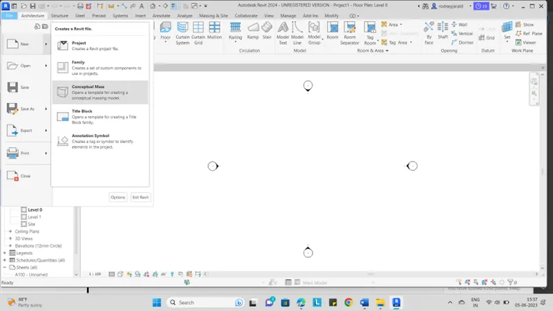
- Click “NEW”
- Choose “Conceptual Mass”
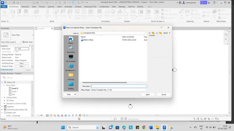
- U will get dialog box called “NEW CONCEPTUAL MASS -SELECT TEMPLATE FILE”
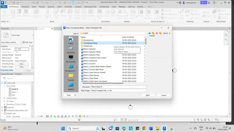
- Than go to “Conceptual Mass” folder
- Than u have option “Metric Mass”
- Select and click “OPEN”
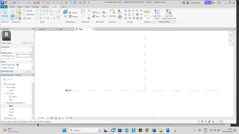
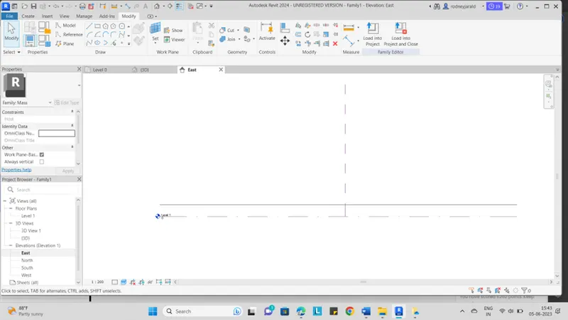
- Go to “ELEVATION “
- Click “LEVEL”
- Than choose the “PICK LINE “option
- Give a offset as 12’
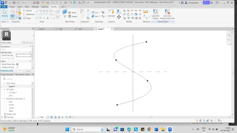
- Go to “FLOOR PLAN”
- Than go to “CREATE “ option
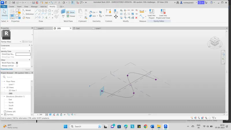
- There is option called “MODEL LINE “
- Than choose the “SPLINE THROUGH POINTS” option
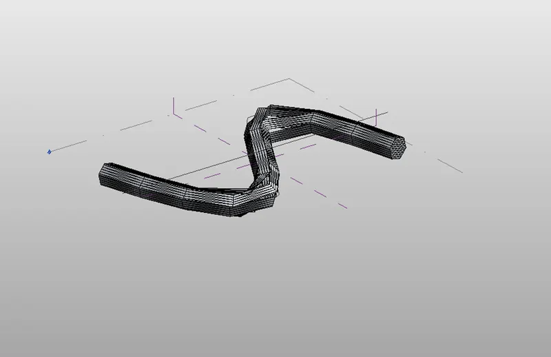
- Than place spline like “S” type
- Go to “3D View” option
- Go to “SET” option
- Click “show”
- set it only in the point
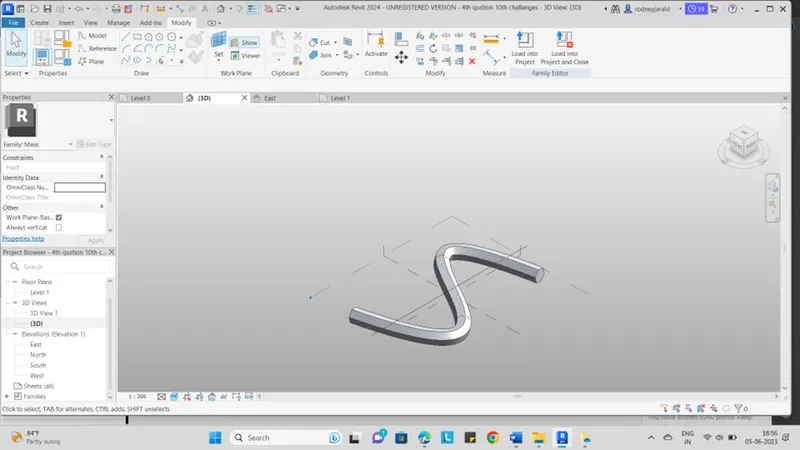
- Than choose “CIRCUMSCRIBED POLYGON”
- Place it I the point give distance of 12’
- Similarly for all the point
- Go to “CREATE” option
- Select the “CURVE “ and first “CIRCUMSCRIBED POLYGON”
- Than drop down create form option
- Click “SOLID FORM”
- Than u will get solid option
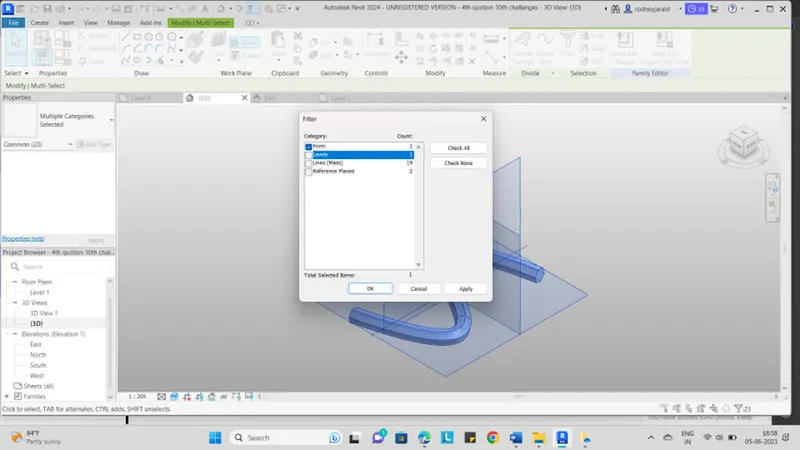
- Select all the solid one
- Click “FILTER” option
- Than choose only “FORM “
- Untick “LINE” option and untick “REFERNCE PLANES”
- Click “OK”
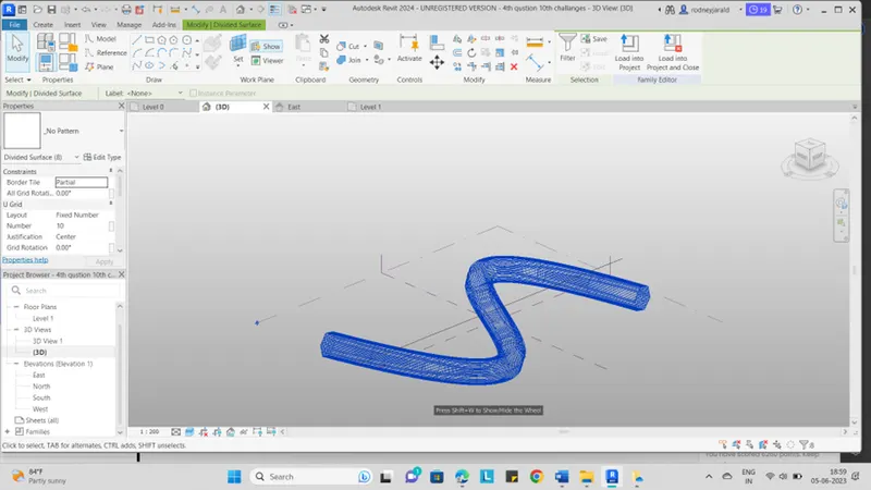
- Select all solid option
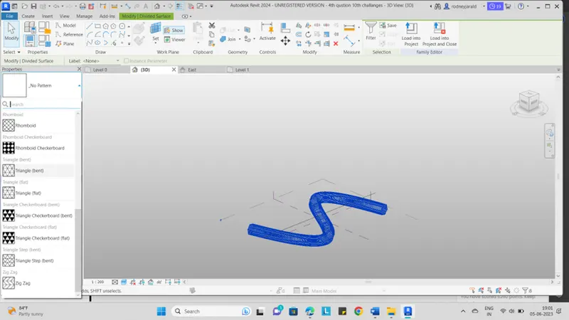
- Than Click “DIVIDE SURFACE”
- Go to “PROPERTIES “
- Choose the “PROPERTIES”
- Than click “TRIANGLE (BENT) “
- Once applied “TRIANGLE (BENT)”
- Finally show the “RESULT “
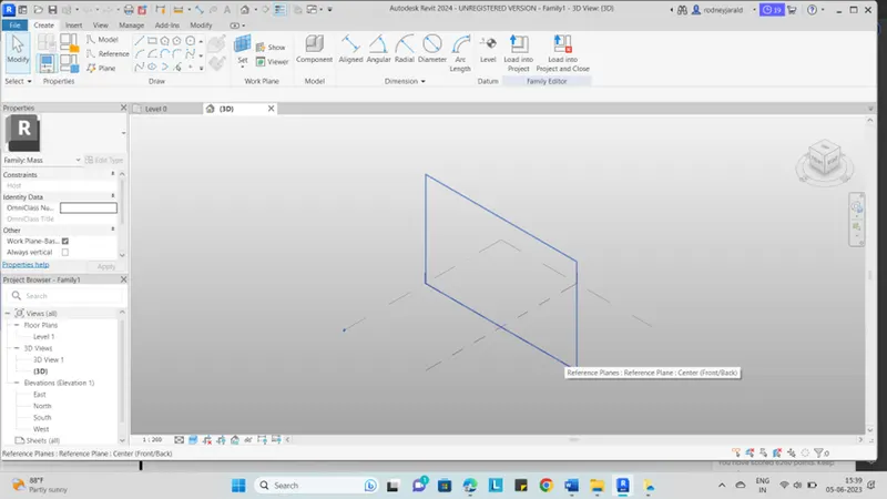
RESULT :
5. Use Dynamo to work on developing a Parametric Stadium. List your parameters and use the visual programming approach to complete the modelling, You can use the concepts discussed in parametric high rise tower in class for reference.
AIM:
To create Dynamo to work on developing a Parametric Stadium
PROCEDURE :
- Open “REVIT 2024” software
- Go to the “NEW PROJECT “
- Select the “ARCHITECUTE TEMPLATE”
- U will get one “NEW PAGE”
- Than Go to the ”MANAGE TAP”
- There is option called “DYNAMO”
- Click the “DYNAMO” option
- Then u will get dynamo dashboard
- Select “NEW” option
- Than u will get “NEW WINDOW “
- Than go to the “search” Option and
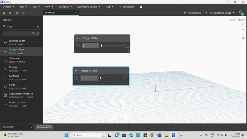
- Type “INTEGEAR SLIDER”
- Than “copy” and past it one time
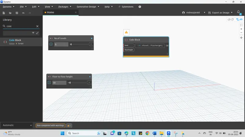
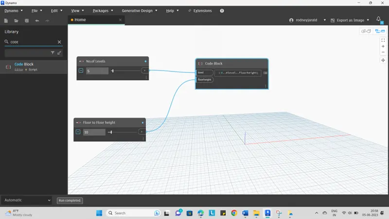
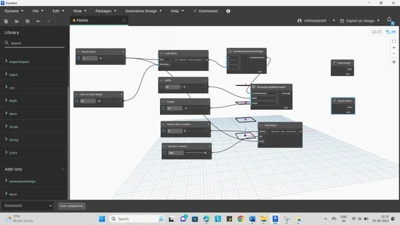
- Change name as “No.of levels” and “Floor to Floor height”
- Set the level as “5” and height as “10”
- Go to “SEARCH” option
- Type “Code block”
- Than manually type code block as “0..#levels..floorheight;
- Than connect “No.of levels “ to “LEVELS”
- Than connect “FLOOR TO FLOOR HEIGHT “ to “FLOOR HEIGHT”
- Go to “SEARCH” option
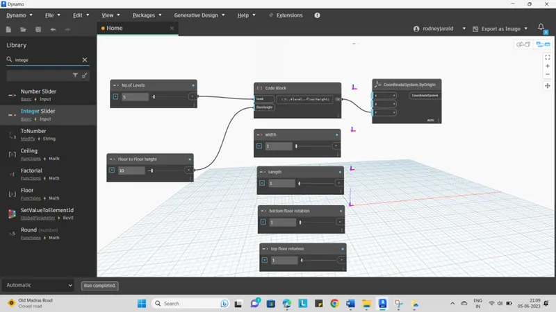
- Type “ORIGIN”
- Than select “BY ORIGIN X, Y, Z”
- Connect “CODE BLOCK” to “COORDINATE SYSTEM.BY ORIGIN “
- Go to “SEARCH” option
- Type “INTEGEAR SLIDER”
- Copy the “INTEGER SLIDER” than past it 3 times
- Change the “INTEGER SLIDER” name as “WIDTH, LENGTH, BOTTOM FLOOR ROTATION, TOP FLOOR ROTATION”
- Go to “SEARCH” option
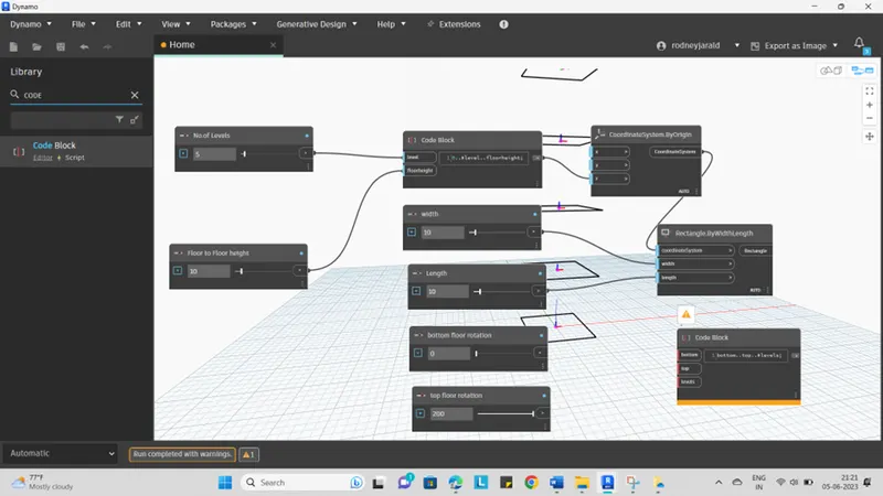
- Type “RECTANGLE .BYWIDTHLENGTH”
- Than connect “coordinatesystem.byorigin” to “Rectangle.bywidthlength”
- Give a width value as “10”
- Length value as “10”
- Connect to “WIDTH” to “WIDTH”
- Connect “LENGTH “ to “LENGTH”
- Go to “SEARCH” option
- Type “Code block”
- Go to “CODE BLOCK”
- Type manually “bottom..top..#levels;
- Connect “BOTTOM FLOOR ROTATION” to “BOTTOM”
- Connect “TOP FLOOR ROTATION” to “TOP”
- Connect “NO.of Levels “ to “Levels” in the “CODE BLOCK”
- Go to “SEARCH” option
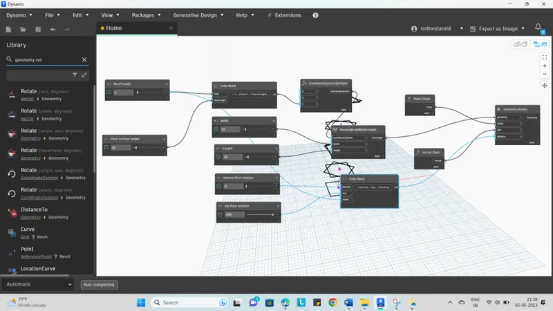
- Type “POINT.ORIGIN” and
- Type “VECTOR.Z AXIS”
- Again Go to “SEARCH” option
- Type “GEOMETRY ROATE “ as “Origin, axis , degrees”
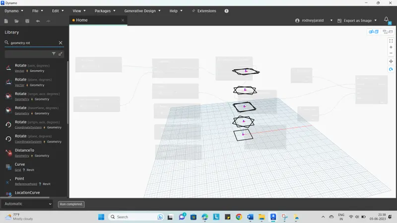
- Connect “RECTANGLE .BYWIDTHLENGTH” to “GEOMETRY.ROTATE”
- Connect “POINT.ORIGIN” to “ORIGIN”
- Connect “VECTOR.ZAXIS” to “AXIS”
- Connect “CODE BLOCK” to “DEGREES”
- Than Go to “search “ Option
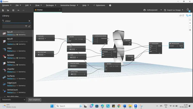
- Type “POLYSURFACE”
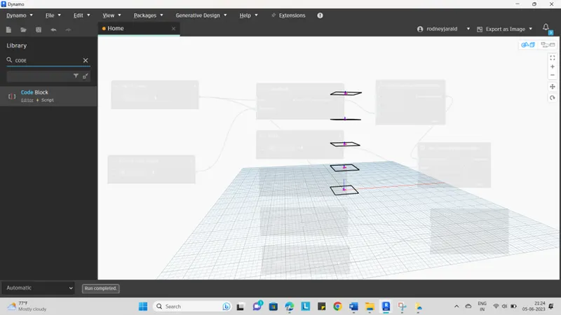
- Connect “GEOMETRY.ROTATE “ to “POLYSURFACE.BY LOFT”
- Once you connected u will get “Parametric Stadium”
- Finally show the result
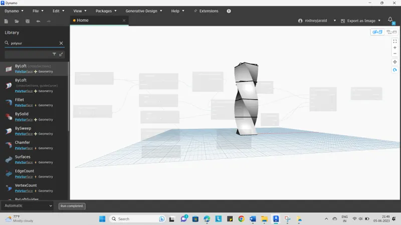
RESULT :