Creating Conceptual mass in REVIT and Creation of Sinusoidal curve and a Parametric stadium using Dynamo
Creating Conceptual mass in REVIT and Creation of Sinusoidal curve and a Parametric stadium using Dynamo
1) Using Dynamo create a set of sinusoidal points and create a curve and create a surface out of the curve.
AIM:To create a set of sinusoidal points and create a curve and create a surface out of the curve by using Dynamo.
Tools and commands:
- Code block
- Range
- Math sin
- Product(*)
- Addition(+)
- List
- Slider integer
- Point by co-ordinates
- NurbsCurve.ByControlPoints
- Surface.ByLoft
PROCEDURE:
STEP-1: Open Revit Software:
- Open the revit software 2023 and click on NEW option
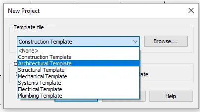
- Select Architectural template in template dialoge box - press ok then open Architectural template
STEP-2: Open Dynamo:
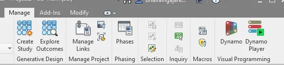
- Open Dynamo tool under the Manage tab in the Ribbon tool bar
STEP-3: Open new Dynamo file:
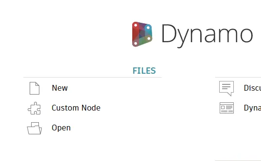
- Click on new in dynamo window
- Dynamo Sheet is open
STEP-4: create a curve surface :
a) Create a set of sinusoidal points:
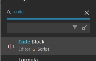
- Go to on search bar enter "Code block"
- Insert 3 code block
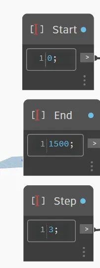
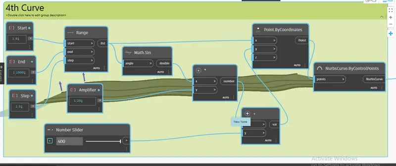
- Give the names to the code box individually as start, end and step and Enter the Values 0,1500,3
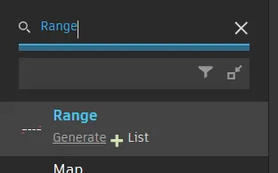
- Then for Insert range again search "Range"
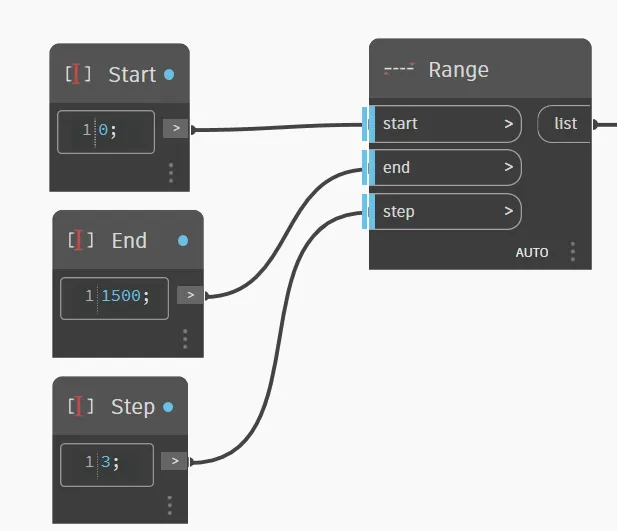
-Select range connect start to start, end to end and step to step as shown in the below figure.
- Next we type the point.bycoordinates and connect list to the x coordinate
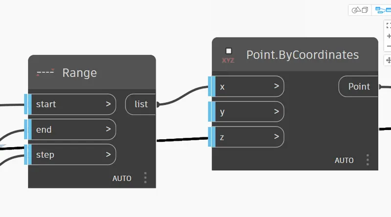
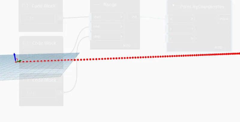
- Insert Math.sin- connect the range to angle
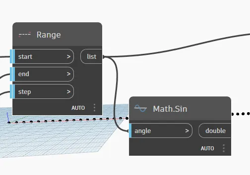
- Insert Product - Math.sin (double) connect to product of x number
- Next type Code block and give name it to amplifier and value is 20- Connect to product of y number
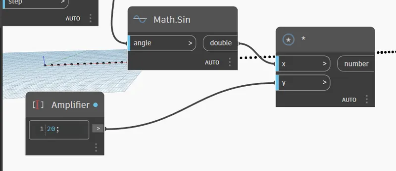
- Add addition. Number is connect to addition of X
- Next type Number slider put value 20 - connect to addition of y
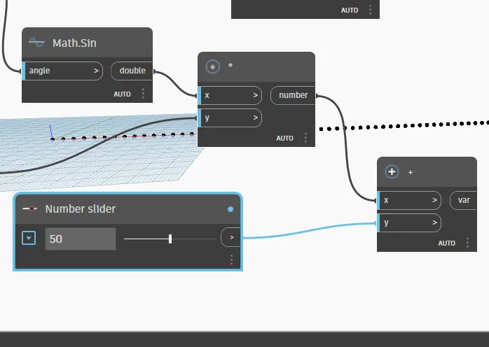
- Addition Var connect to y of point.ByCordinate
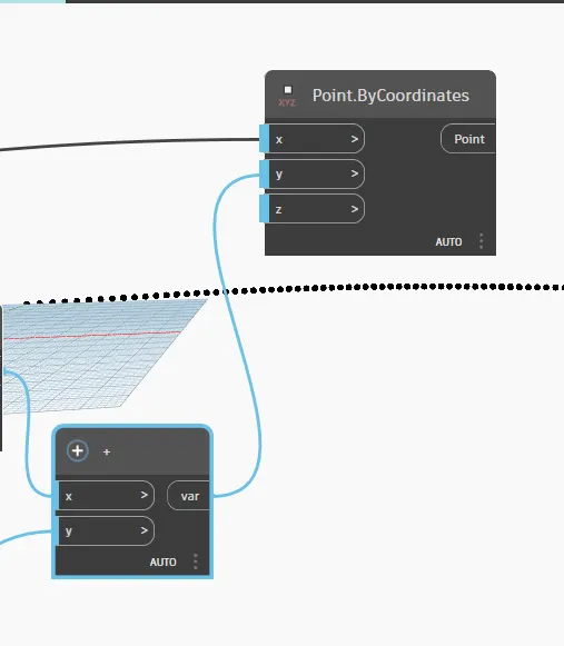
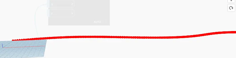
-A set of sinusoidal points are created.
b) Create a curve:
- Next Type and insert NurbsCurve.ByControlPoints
- Point connect to NurbsCurve.ByControlPoints
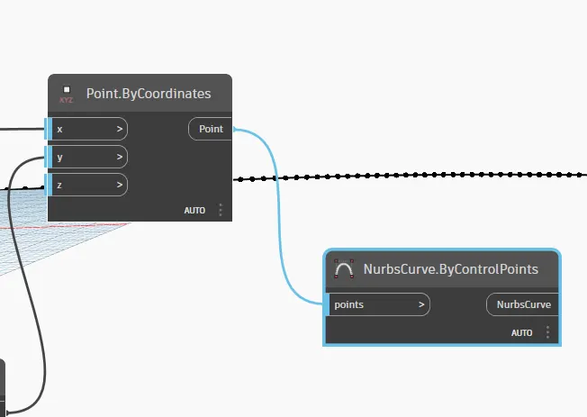
- Curve is created to connecting the set of sinusoidal points
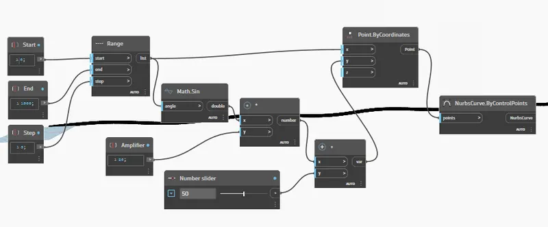
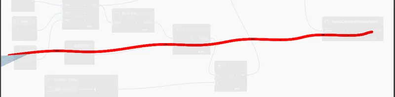
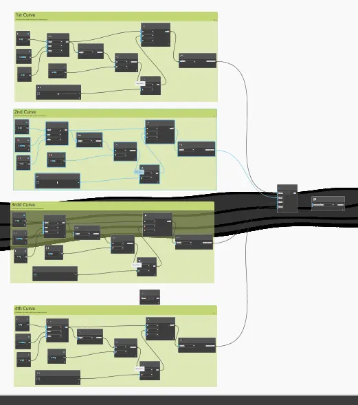
In dynamo
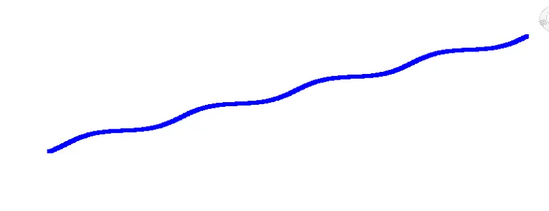
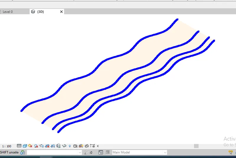
In Revit
c) Create a surface out of the curve:
*Create a group:
- Select all nodes
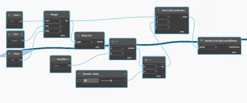
- Click on edit - select create group
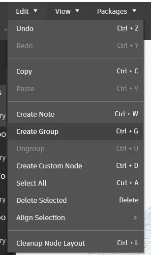
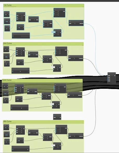
- Give a title name to group as a"1st curve"
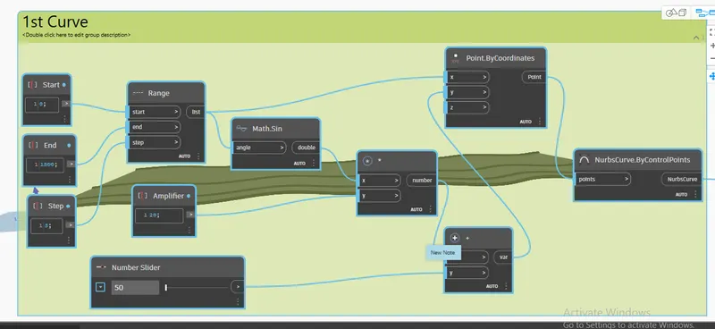
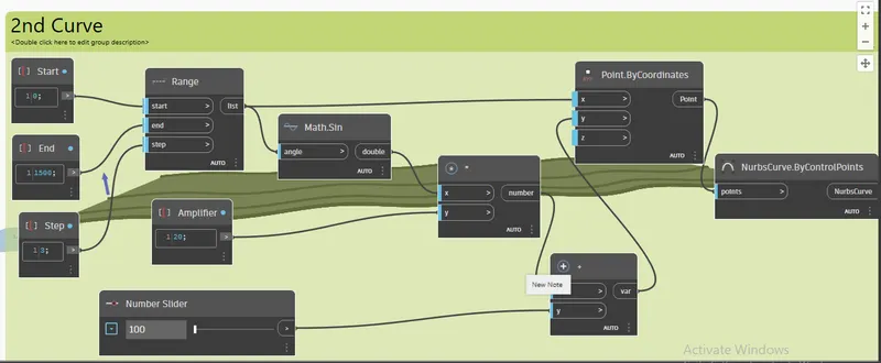
- Select the group copy it and paste 3times
- Give name them as a "2nd curve", "3rd curve", "4th curve"
- Change there amplitude by using number silder- 2nd:100, 3rd:200, 4th:400
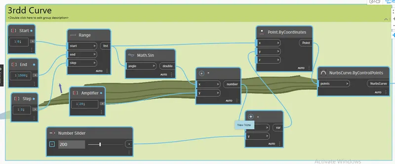
* Create a Surface:
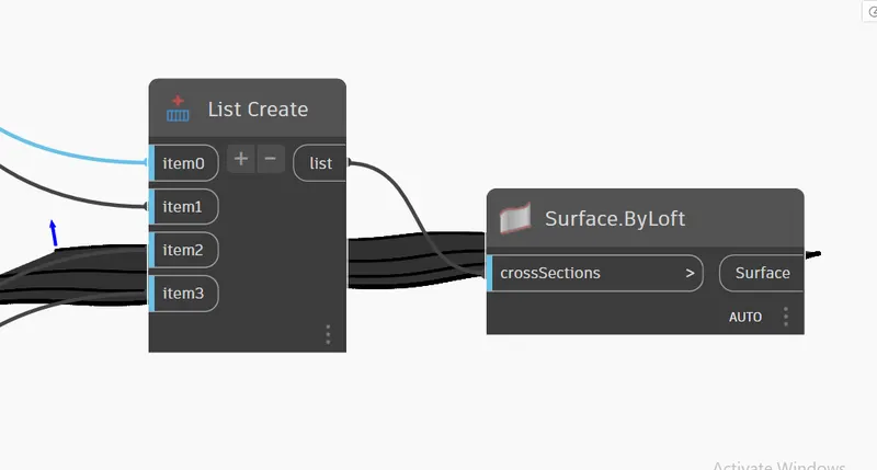
- Insert the list - add list numbers i.e. list0, list1, list2, list3 by click on + this sign
- Connect nurbscurve of all 4 groups to the 4 items in the list.create. i.e.1st group nurbscurve connect to list0 , 2nd group nurbscurve connect to list1 ,3rd group nurbscurve connect to list2 and 4th group nurbscurve connect to list3 ,
- Add Surface.ByLoft - List is connected to Surface.ByLoft
- The surface is created
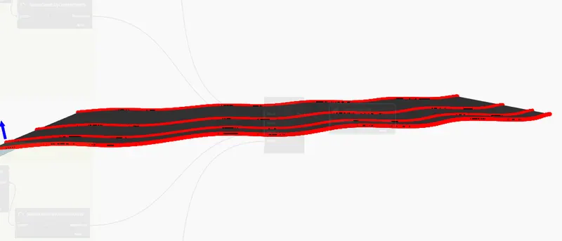
Result: The curve surface is created by using sinusoidal points and curve.
2) Create a conceptual layout of floor plan in dynamo . Using the tools available in dynamo link the lines to appropriate model elements in Revit by choosing the wall types and wall parameters. Make use of the sliders to slide through the height of the wall and length of the wall.
AIM:To create a layout of floor plan by using Dynamo.
Tools and commands:
- Code block
- Sequence
- Geometry.Translate
- String
- Level.ByElevationAndName
- List Create
- Wall Types
- Floor Types
- Floor.ByOutlineTypeAndLevel
- PolyCurve.Curves
- Wall.ByCurveAndHeight
PROCEDURE:
STEP-1: Open Revit Software:
- Open the revit software 2023 and click on NEW option
- Select Architectural template in template dialoge box - press ok then open Architectural template
STEP-2: Open Dynamo:
- Open Dynamo tool under the Manage tab in the Ribbon tool bar
STEP-3: Open new Dynamo file:
- Click on new in dynamo window
- Dynamo Sheet is open
STEP-4: Create a floor plan:
a) Create levels:
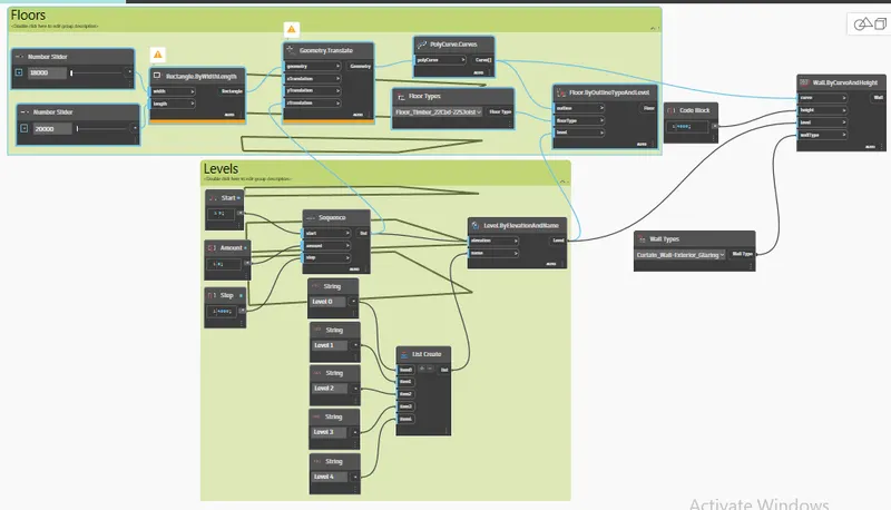
- Go to on search bar enter "Code block"
- Insert 3 code block
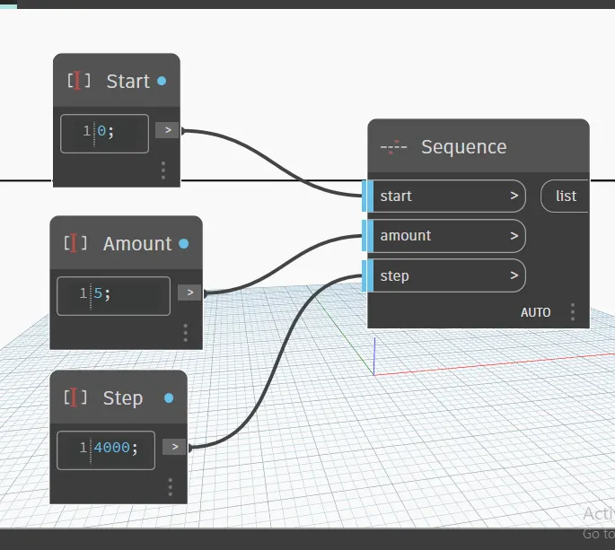
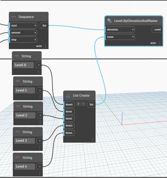
- Give the names to the code box individually as start, end and step and Enter the Values 0,5,4000
- Next type and insert Sequence
- Connect start to start, end to end and step to step to a sequence as shown in the below figure.
- Insert String- Select it press ctrl+c for copy and ctrl+v for paste (4times for getting new 4 string)
- insert name Level 0,.......Level 4
- Provide list create - Add item number by click on +
- Connect Level 0 to item0, Level 0 to item0, Level 1 to item1, Level 2 to item2, Level 3 to item4, and Level 4 to item4,n to a list create
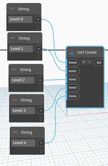
- Add Level.ByElevationAndName - sequence list connect to elevation and liste created list is connect to name
-
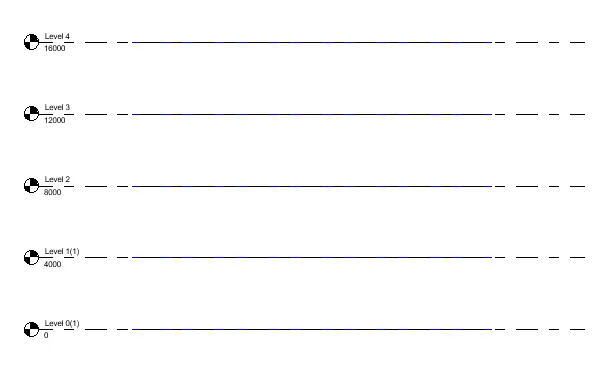
-Levels are created then Select all node and create group - Give name as a levels

b) Create Floor:
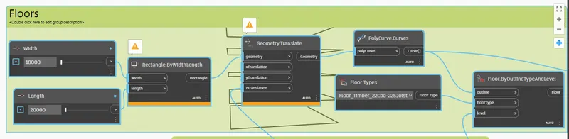
- Next Type and insert Integer slider (2times) - Put min and max value
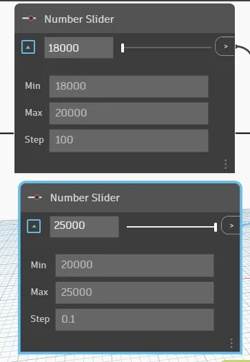
- Give a name as a width and length.
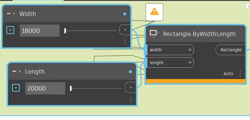
- Next type and insert Rectangle.BywidthLength
- Then connect to width to width and length to length
- Insert Geometry.Translate
- Connect Rectangle to gemeometry and list of sequence to zTranslation
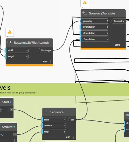
- Next type and insert PolyCurve.Curves - Geomerty connect to polycurve
- Insert Floor.ByOutlineTypeAndLevel - Then connect curve[] to outline
- Add Floor type select floor type as a floor_Timber_22Cdb - connect to floor type to floor type
- Lastly Level of Level.ByElevationAndName connect to Wall.ByCurveAndHeight of level
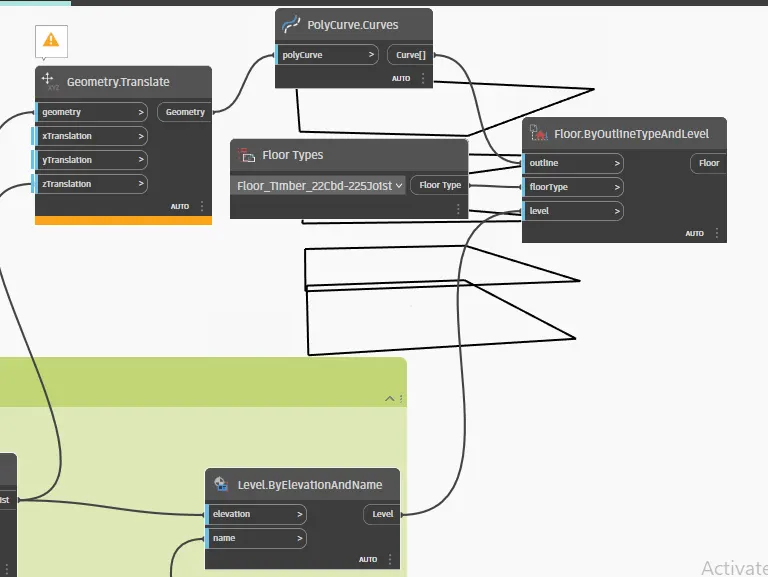
- Floors are create then select a all nodes and create a group - give name to group as a "Floors"
c) Create Wall:
-Next type and inser Wall.ByCurveAndHeight - Then connect curve[] to curve of Wall.ByCurveAndHeight
- Insert code block and give value as 4000. This code block is connect to height of Wall.ByCurveAndHeight
- Level.ByElevationAndName of level connect to level of Wall.ByCurveAndHeight
- Again add wall type - select wall as a curtain_wall_exterior_glazing - And connect to wall type
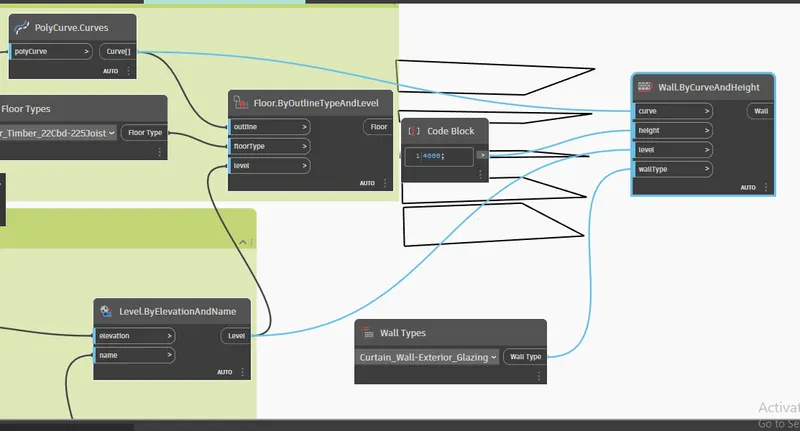
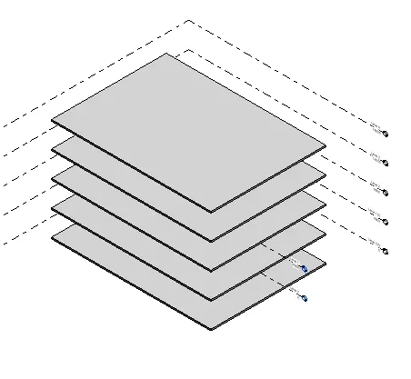
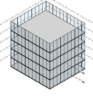
Result: The conceptual layout of floor plan is create in dynamo
3) Create an array of model elements in Revit. Use dynamo to vary the properties of model elements by using the slider or code block
AIM: CREATE AN ARRAY OF MODEL ELEMENT IN REVIT USING DYNAMO
Tools and commands:
PROCEDURE :
STEP-1: Open Revit Software:
- Open the revit software 2023 and click on NEW option
- Select Architectural template in template dialoge box - press ok then open Architectural template
STEP-2: create a array in revit :
- Draw rectangle -select it - and click on array in modify tab - provide distance and number as 2000 and 3 horizontal array is drawn
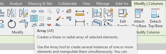
- For vertical array select all horizontal colcoumn then give distance 2000 and number as 3
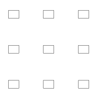
- Select all and make a ungroup
STEP-3: Open Dynamo:
- Open Dynamo tool under the Manage tab in the Ribbon tool bar
STEP-4: Open new Dynamo file:
- Click on new in dynamo window
- Dynamo workspace is open
STEP-5: Rotate the element:
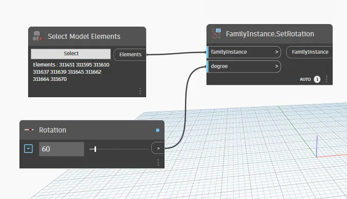
- Next we type the select model elements, integer slider name as a rotation provide value 0-360
- Add select model element
- After that click on select - Goes on revit workspace select all model elemet
- Next connect integer slider to the degree of familyinstance.SetRotation (multiple), as shown in the below figure.
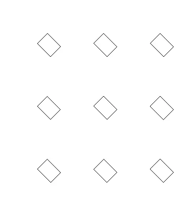
-Next the columns are rotated to the 60 degrees, as shown in the below figure.
Result: Create an array of model elements in Revit and roatate them by using of dynamo
4) Create a conceptual mass in Revit and develop a parametric column by dividing the surfaces and apply the concepts similar to used in parametric walkway modelling. Use triangular bent or square shaped panels to add finish to the parametric column
AIM:To create a coceptual mass.
Tools and commands:
- Families.
- Conceptual mass.
- Level.
- Set.
- Referance.
- Filter.
- Pattern.
- Divide surface.
- Create form.
PROCEDURE:
STEP-1: Open Revit Software and cocneptual mass:
- Open the revit software 2023 and click on NEW option in Families
- Select Coceptual mass folder - choose metric mass - click on open
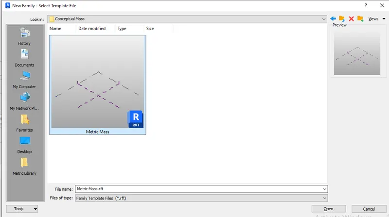
STEP-2: Create Parametric Coloumn:
- Go to project browser select east in elevation
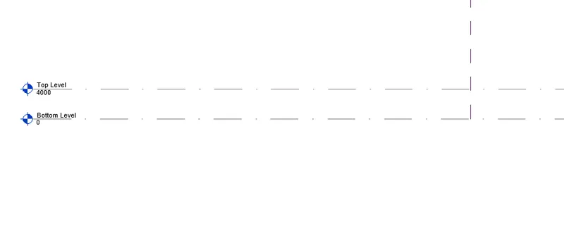
- For adding level click on level

- Draw the level at 4000mm
- Give name both as top level and bottom level
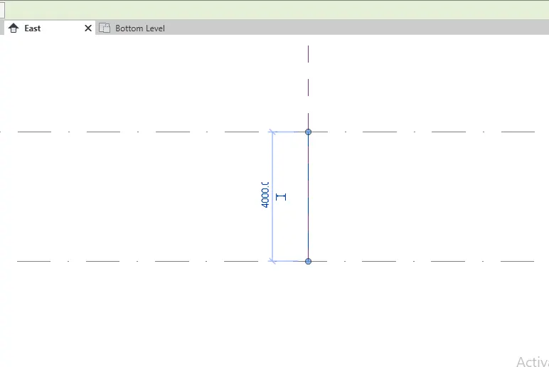
- For draw the path line select model line
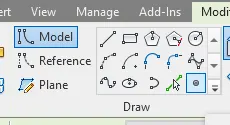
- `Draw it on doted center line
- Select point element in draw section
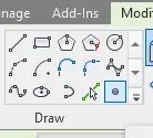
- Place the dot at top and then one by one as 5 times
- Having distance from top is 0,500,1000,1500,4000
- Then go to on 3D view
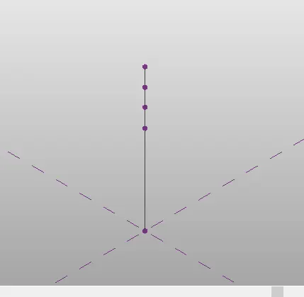
- Select bottom point
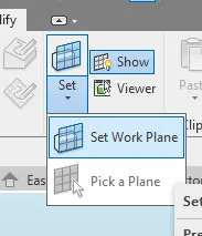
- Click on set work plane and then show
- Draw rectangle by using of circumscribe polygon - Give the side:4
- Draw 1st rectangle at bottom as size 400 then,2nd:400, 3rd:500, 4th:650 5th:850
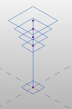
- Select 1st vertical line then press ctrl and select rectangles one by one in same direction
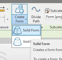
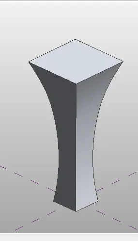
- Click on create form-select solid form
STEP-3: Divide surface:
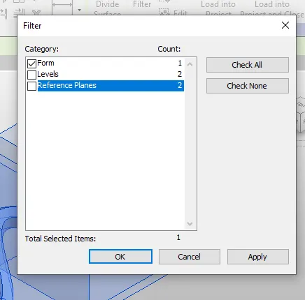
- Select whole object - Go on filter - click on check none - check box form - click on ok
- Select on divide surfce
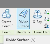
- Surface is divide in 6 part
STEP-4: Apply Grid pattern:
- Again select whole object goes on filter -select form press enter
- Choose grid pattern from properties browser as a rectangle
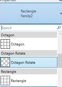
-select object then Provide number of u grid is 10 and v grid is 5
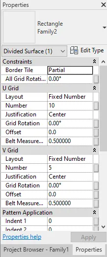
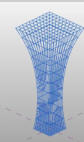
STEP-5: Create Metric curtain pattern:
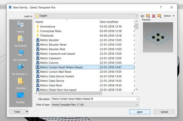
- Go on flie tab -select new
- choose family
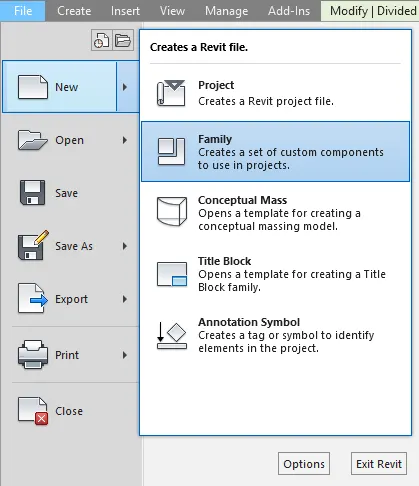
- Select curtain panel pattern based - open
- Place point element on mid of grid line
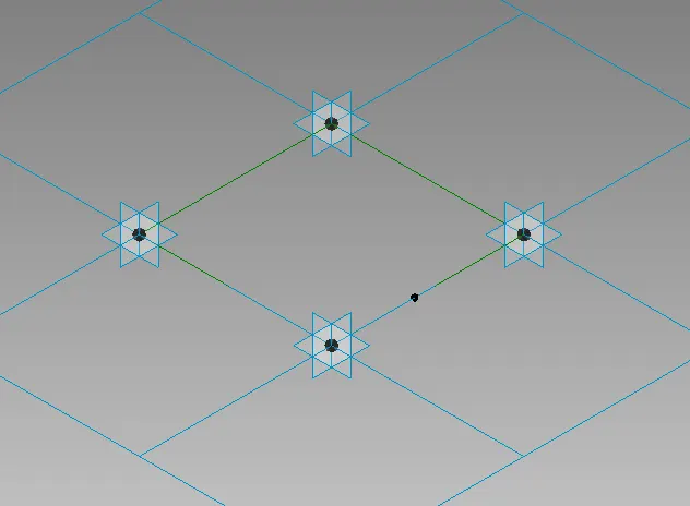
- Then set a work plane on click this option - After that click on rotate
- Rotate 3d cube for see this plane
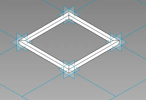
- Draw rectangle by using of circumscribe polygon - Give the side:4 having size is 10
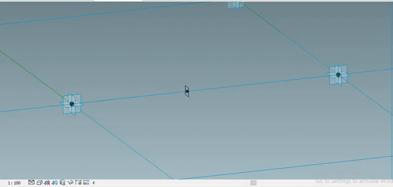
- Then select path as a grid line press ctrl and clcik on rectangle
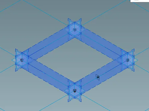
- Select create form as solid form
- Click on load into project
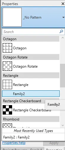
- Again select object click on filter-choose only form- ok
- Select pattern as a family 2 from properties browser
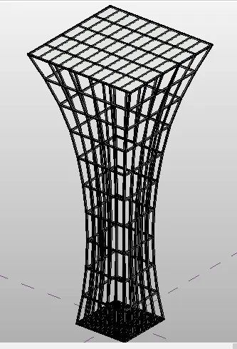
Result: Create a conceptual mass of a parametric column in Revit and develop by dividing the surfaces and apply the square shaped panels
5) Use Dynamo to work on developing a Parametric Stadium. List your parameters and use the visual programming approach to complete the modelling, You can use the concepts discussed in parametric high rise tower in class for reference.
AIM:To create a parametric stadium.
Tools and commands:
- Number slider
- Point.ByCoordinates
- Code block
- Curve.PointAtParameter
- PolyCurve.ByPoints
- Plane.XZ and Plane.YZ
- Geometry.Translate
- EllipseArc.ByPlaneRadiiAngles
- Ellipse.ByOriginRadii
- Geometry.DistanceTo
- CoordinateSystem.Rotate
- Surface.ByLoft
PROCEDURE:Surface.ByLoft
STEP-1: Open Revit Software:
- Open the revit software 2023 and click on NEW option
- Select Architectural template in template dialoge box - press ok then open Architectural template
STEP-2: Open Dynamo:
- Open Dynamo tool under the Manage tab in the Ribbon tool bar
STEP-3: Open new Dynamo file:
- Click on new in dynamo window
- Dynamo Sheet is open
STEP-4: Create vertical line:
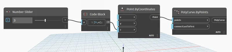
- Type and insert number slider - add min and max value are 1 and 6 - add 3 on box
- Add code block - put value [0,a] - connect number slider to code block
- Insert Point.ByCoordinates - connect code block to Point.ByCoordinates
- Next type and insert PolyCurve.ByPoints point of Point.ByCoordinates to point of PolyCurve.ByPoints
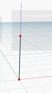
- Create vertical line with two points
STEP-5: Create vertical point on line:
- Next type and insert code block - put value 0..1..#4
- Add Curve.PointAtParameter
- Then connect polycurve to curve and code block to param
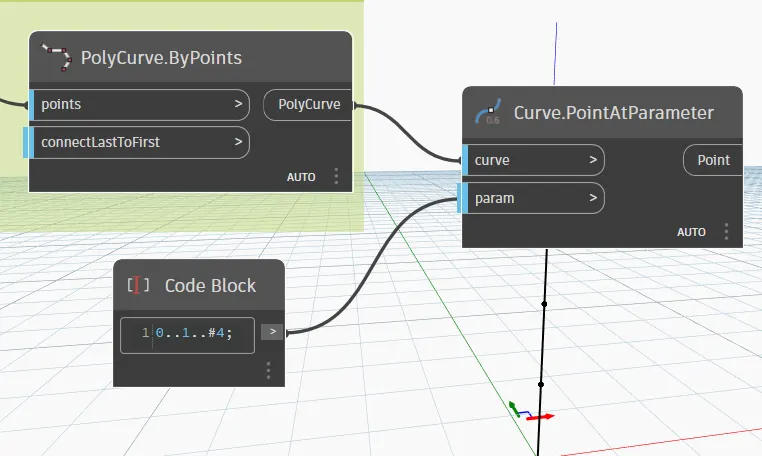
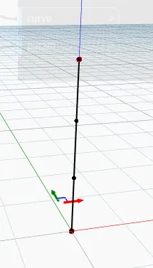
- Points are creates on line
STEP-6: Create ellips arc :
- Insert plane.YZ and code block give value (a/2) - Number slider (which is insert at starting) connect with code block
- Add Geometry.Translate
- Plane.YZ connect to geometry and code block connect with zTranslation
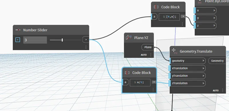
- After that add Plane.XZ and Geometry.Translate
- Plane.XZ connect to geometry and code block connect with zTranslation
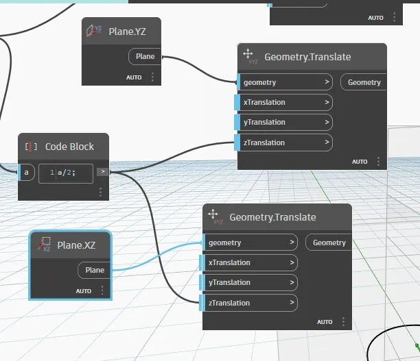
- Insert EllipseArc.ByPlaneRadiiAngles - connect geometry to plane
- Add 2 number slider give their min and value as a 1 and 10 and their actual value are
- Provide their value 2.5 and 3.5- connect to 2.5 to xRadius of 1st EllipseArc.ByPlaneRadiiAngles and 3.5 to yradius of 2nd EllipseArc.ByPlaneRadiiAngles
- Add code block and provide value 90 and 0 which is connect to both start angle of EllipseArc.ByPlaneRadiiAngles
- Then code block having value is a/2 connect to yRadius of 1st EllipseArc.ByPlaneRadiiAngles xradius of 2nd EllipseArc.ByPlaneRadiiAngles
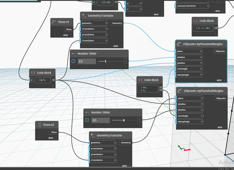
- The ellips arc are created
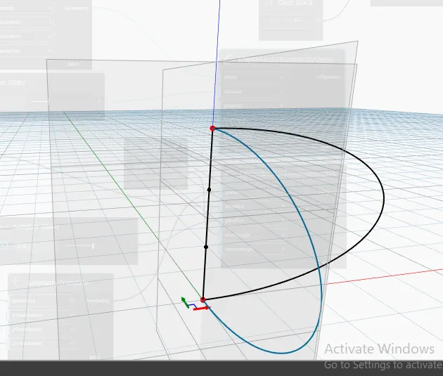
STEP-7: Create points on ellips arc :
-Insert code block - put value 0..1..#6
- Add 2 Curve.PointAtParameter - Connect ellipsearc to curve and coe block to param both
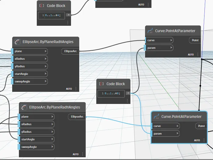
- The points are created on ellips arc
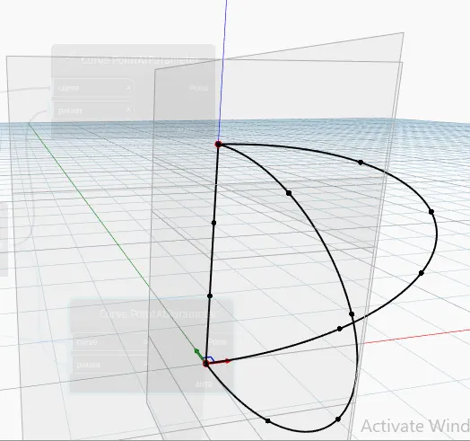
STEP-8: Create ellips:
- Add 2 Geometry.DistanceTo -Connect Polycurve to both geometry and both point connect to both other
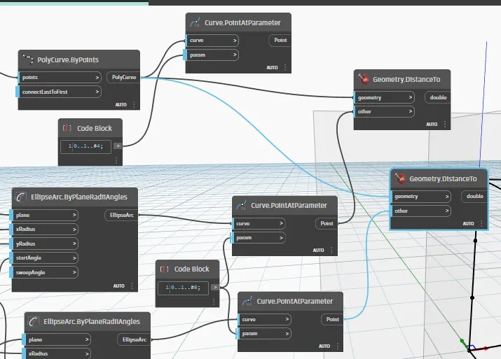
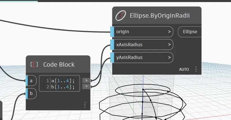
- Insert code block -Give value a[1..4] and b[1..4]
- Both double connect to code block a & b
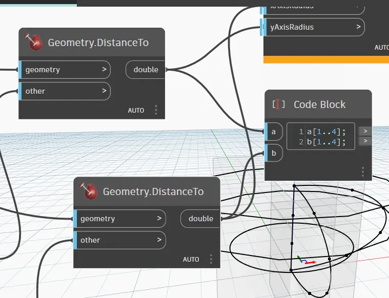
- Type and insert Ellipse.ByOriginRadii - Connect Curve.PointAtParameter of point to origin
- Code block "a" value to yAxisRadius and "b" value to xAxisRadius
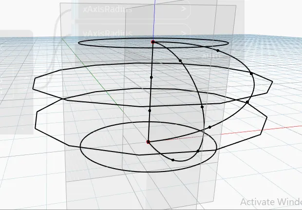
- Create elliptical shape
STEP-9: Create points on ellips :
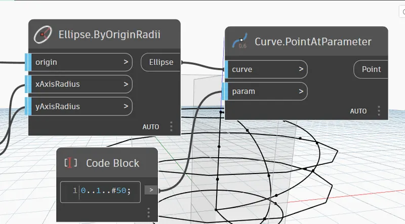
- Type and insert code block - provide valuve as 0..1..#50
- Again add Curve.PointAtParameter
- Connect ellipse to curve and code block to param
- Select the arrow( >) of curve and choose the use level - then click on downward arrow to get a @L1
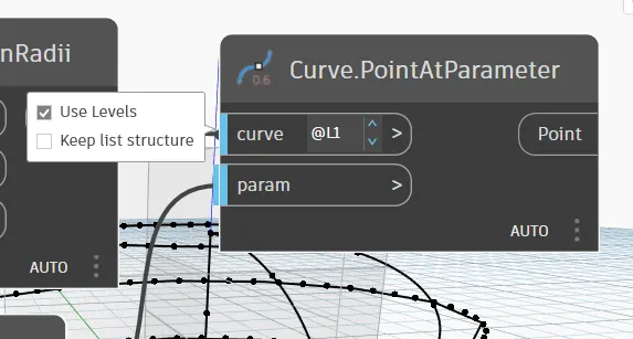
- Points are created
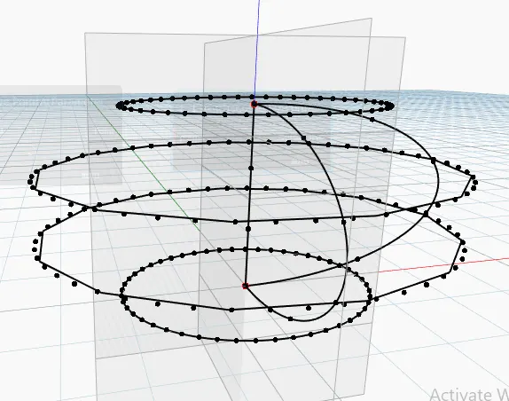
STEP-10: Create surface:
-
- Next insert NurbsCurve.ByPoints - Point connect to point
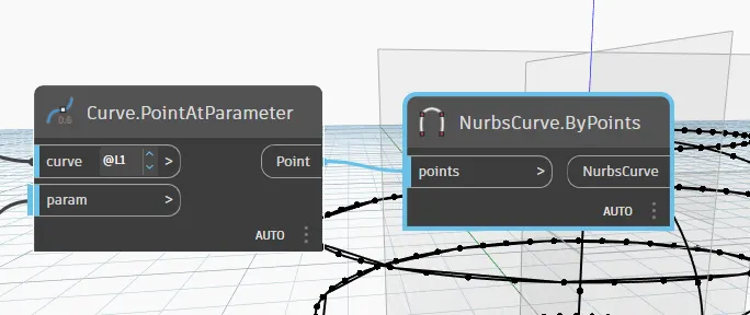
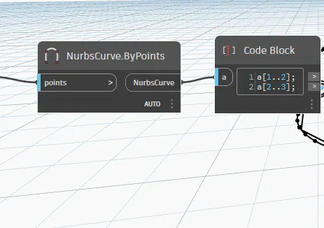
- Add Code block - insert value as a a[1..2] and a[2..3]
- NurbsCurve connect to a
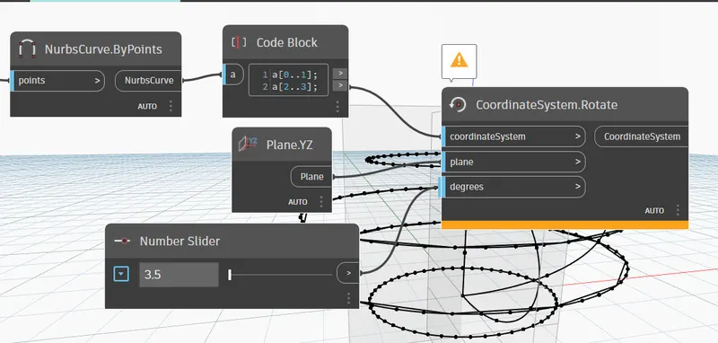
- Insert Plane.YZ and number slider put the value of number slider is 3-6
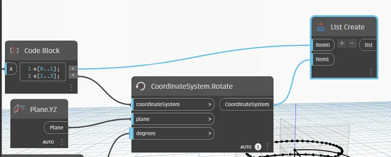
- Next type and add CoordinateSystem.Rotate - Connect code block 2nd value to CoordinateSystem, plane to plane and number slider to degree
- Insert List Create - add item1 by click on + then Connect code block 1st value to item0 and CoordinateSystem to item1
- Choose Surface.ByLoft - List is connect with cross section
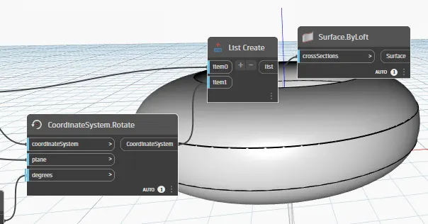
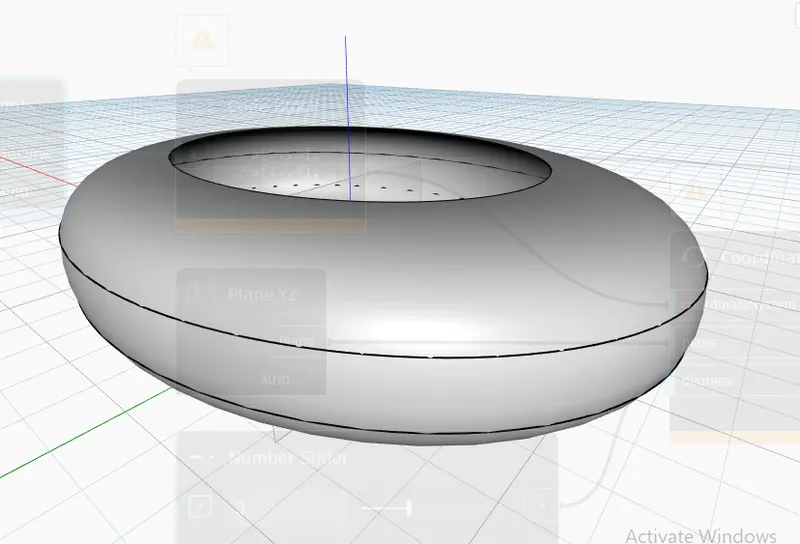
- Parametric stadium is created
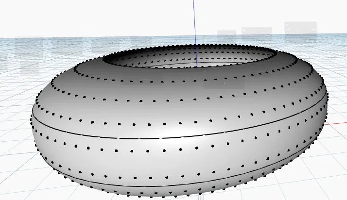
Result: Creating a Parametric Stadium by uisng dynamo
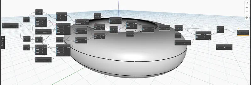
- Select all nodes and right click on free space anywere - select hide geometry getting reuslt.