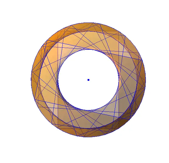
Creating Conceptual mass in REVIT and Creation of Sinusoidal curve and a Parametric stadium using Dynamo
1.
AIM
To create sinusoidal point then curve from the point and then create surface
INTRODUCTION
By using dynamo created a sinusoidal point then created a curve from the point and converted into the surface
PROCEDURE
OPEN DYNAMO
- Open Revit software
- In new architectural template
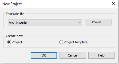
- Go to manage tab, click on dynamo under visual programming

- Dynamo window will open
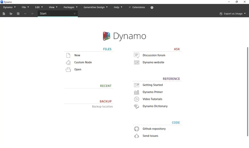
CREATE NEW FILE IN DYNAMO
- Then dynamo window opens and then go to new option
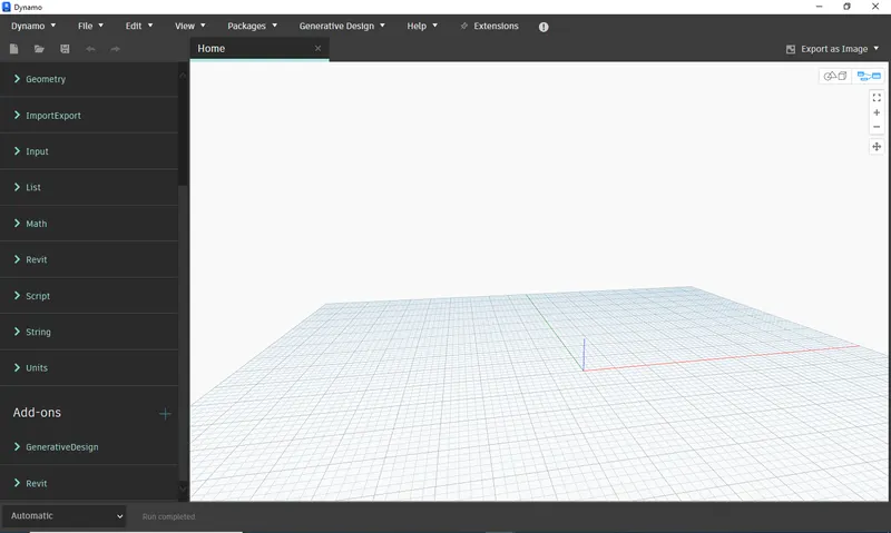
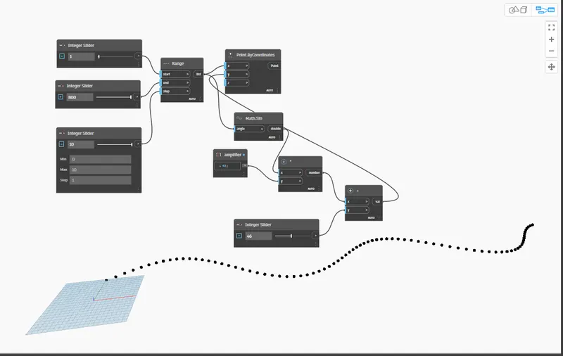
CREATE SINUSOIDAL POINT
- Insert 3 Integer Slider from Library and rename accordingly for Start, End and Step
- Insert Range and connected all inputs from Sliders
- Insert Point.ByCoordinate and connect “X” with seq (output of Range)
- Insert Math.sin and provided input from seq (output of Range)
- Insert Multiplication and CodeBlock (renamed with Curve)
- Provided inputs for multiplication from Math.sin and Curve
- Insert one more Integer Slider (renamed with Y-Point) and one Addition
- Provided inputs for addition from Y-Point and Multiplication
- Given output of addition to “z” point of Point.ByCoordinate
CREATE CURVE
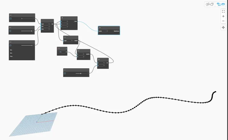
- Insert NurbsCurve.ByControlPoints
- Provided input to NurbsCurve.ByControlPoints from output of Point.ByCoordinate
- This will create Curve on the Sinusoidal points
CREATE SURFACE
- Copy all the input nodes and output nodes and past it 2 times
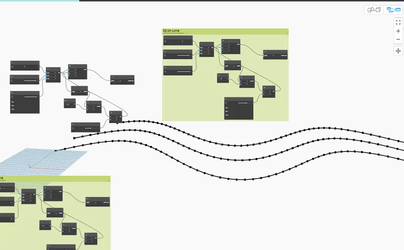
- Change the value of Y-Points
- Insert one List and provide the output of SinWave as an input to List
- Insert one Surface.ByLoft and provide the output of List as Input of Surface.ByLoft
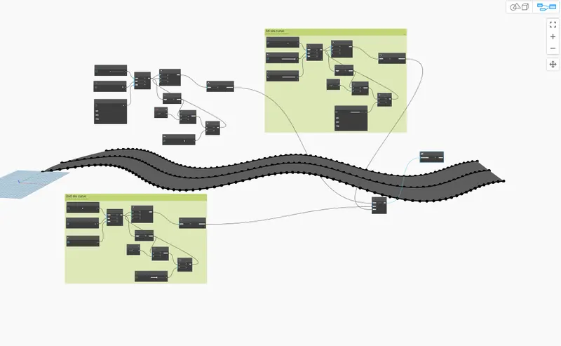
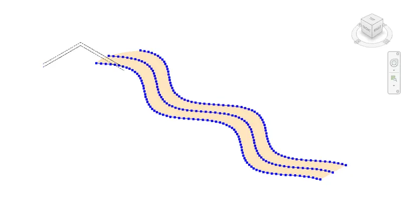
- In 3D view
RESULT
Succesully completed a set of sinusodial points.
- Successfully completed a sinusodial curve.
- Succesfully completed a surface out of the curve.
2.
AIM:
By using dynamo created conceptual wall layout of floor plan
INTRODUCTION:
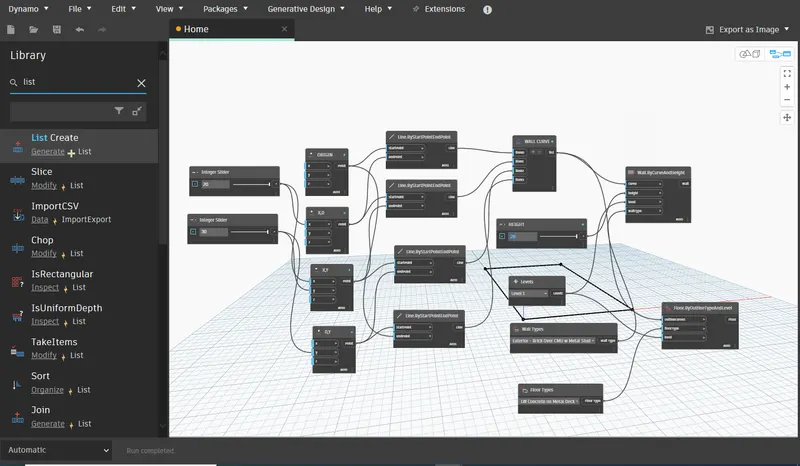
To create the conceptual layout of a floor plan in dynamo, used available tool for joining the line, wall type and floor type and used sliders for height and length of wall
PROCEDURE:
OPEN DYNAMO
- Open Revit software
- In new architectural template
- Go to manage tab, click on dynamo under visual programming
- Dynamo window will open
- Create a new dynamo model
CREATE POINT
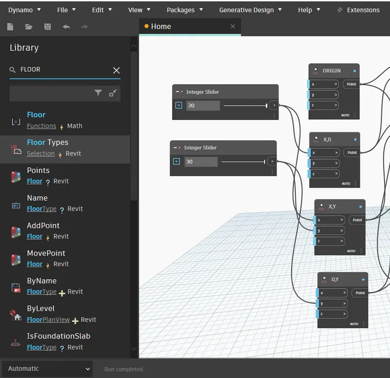
- Insert 2 integer sliders and rename with x range and y range
- Insert 4 Point.ByCoordinates and rename them accordingly i.e. origin,( x,0), (x, y,),( 0,y)
- Connect the output of integer sliders as an input of Point.ByCoordinates accordingly
- 4 points created, based on the length and width
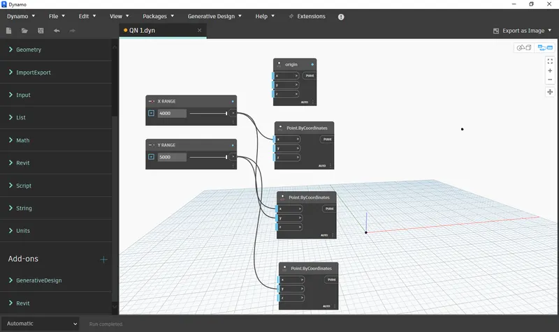
- The points are created
CREATE LINE
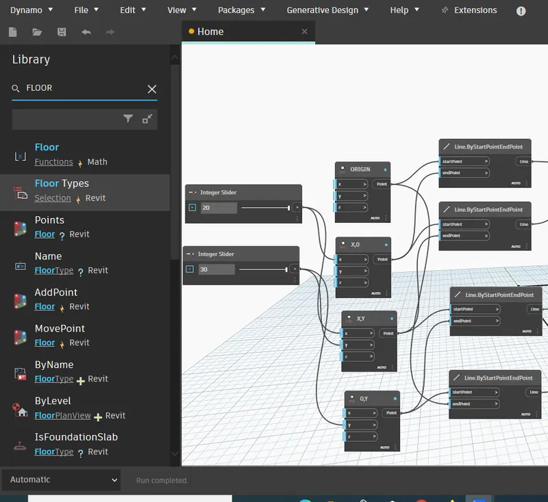
- Insert 4 Line.ByStartPointEndPoint
- Provide output Point.ByCoordinates as an input of Line.ByStartPointEndPoint to connect the line between point accordingly
PROVIDE LEVEL, WALL TYPE AND HIGHT OF THE WALL
- Insert a List Create, add the 4 items in list and rename as wall curve
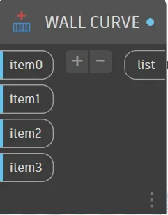
- Connect the outputs of each Line.ByStartPointEndPoint to one-by-one list items
- Insert Levels and select the level1
- Insert Integer slider and rename as Hight and change the Hight as required
- Insert Wall.ByCurveAndHight and provide the inputs from List, Level, Wall Type and Hight
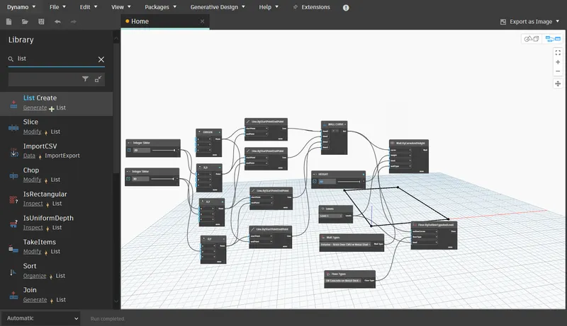
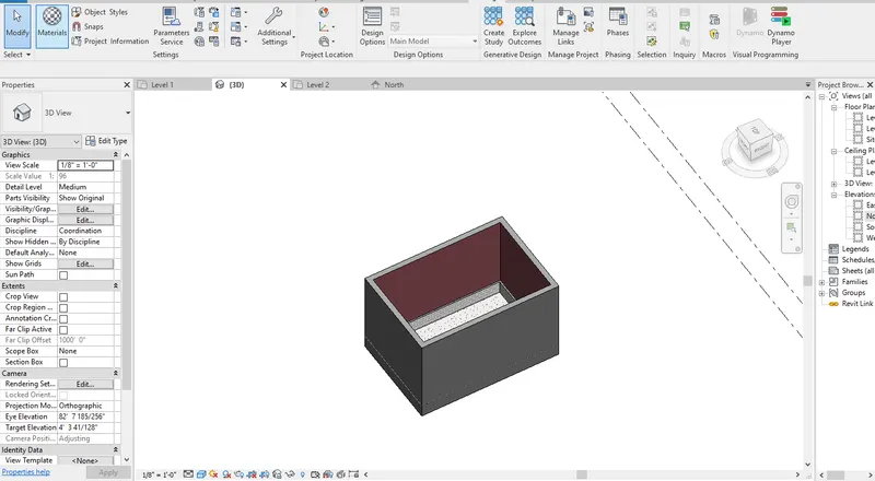
- The 3d view of wall
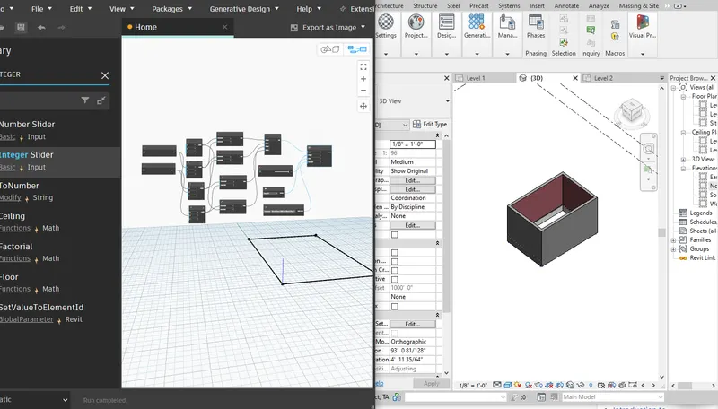
PROVIDE FLOOR TYPE
- Insert Floor Type
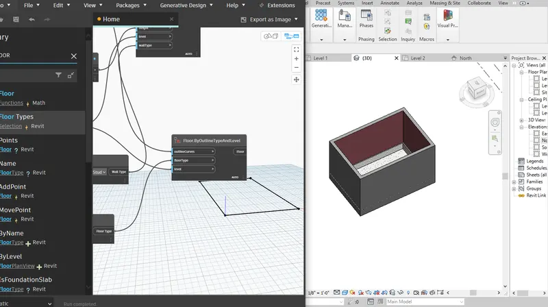
- Insert Floor .By Outline Type And Level
- Provide the input for Floor.ByOutlineTypeAndLevel from List, Floor Type and Level
- Add floor to the model
RESULT:-
- Successfully completed the conceptual layout of floor plan in dynamo using the tools available in dynamo link.
- The height of the wall and length of the wall has been changed using the sliders.
3.
AIM:
To create an array of elements in Revit and vary the properties by using slider or code block in dynamo
INTRODUCTION:
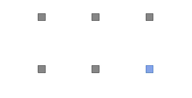
Created the array of columns in Revit and by using the integer slider from dynamo, rotate the column in Revit
PROCEDURE:
OPEN REVIT AND CREATE ARRAY OF COLUMN
- Open Revit software
- In new architectural template
- Go to architecture and select architectural column
- Insert 4 columns as shown
OPEN DYNAMO
- Go to manage tab, click on dynamo under visual programming
- Dynamo window will open
- Create a new dynamo model
STEP 3) CREATE ROTATION IN DYNAMO
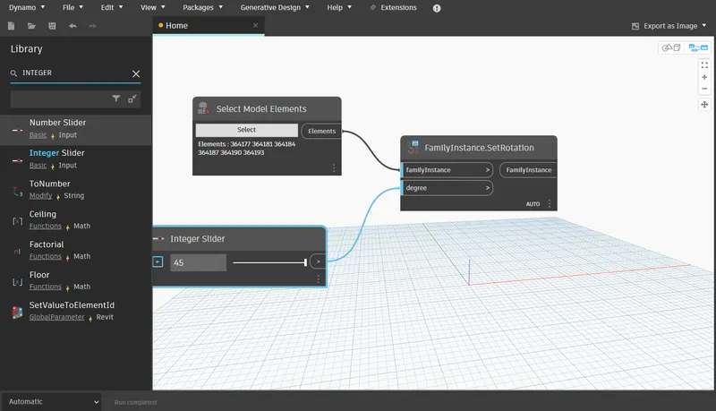
- Insert Select Model Elements
- Click on Select and select the all the column from Revit
- Insert Integer Slider and provide the angle to the slider
- Insert FamilyInstance.SetRotation and provide inputs from Select Model Element and Integer Slider
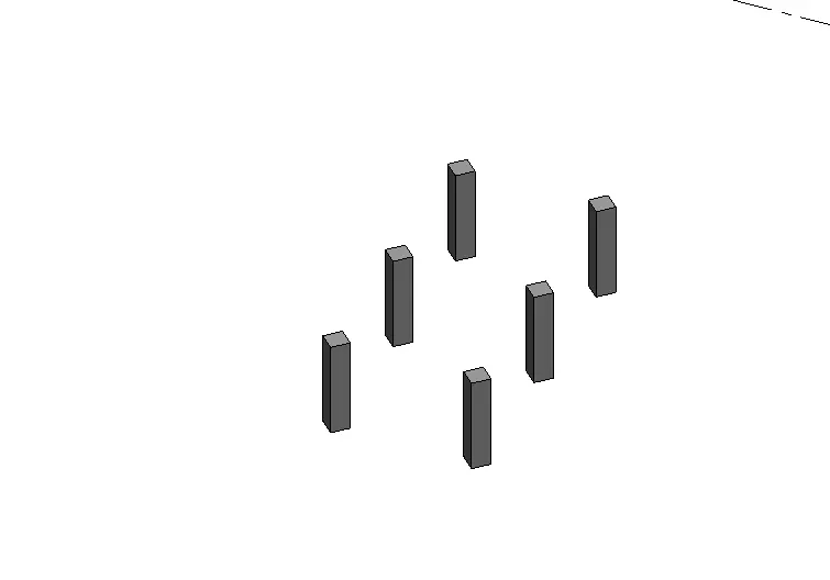
RESULT:-
Successfully completed an array of model elements in revit using dynamo to vary the properties of model elements by using the slider or code block.
4.
AIM:
To Create the Conceptual Mass in Revit, create a form and use property of triangular bent icon in the parametric column
INTRODUCTION:
Created a Conceptual Mass and developed a parametric column by dividing the surface and finish the model by using triangular bent shape
PROCEDURE:
OPEN CONCEPTUAL MASS
- Open Revit software
- Go to File tab > from new select Conceptual Mass
- Select Metric Mass from Conceptual Mass folder > click Open
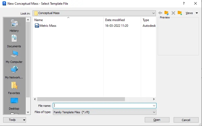
- After selecting the mass from the conceptual mass folder the new screen will be visible, as shown below.
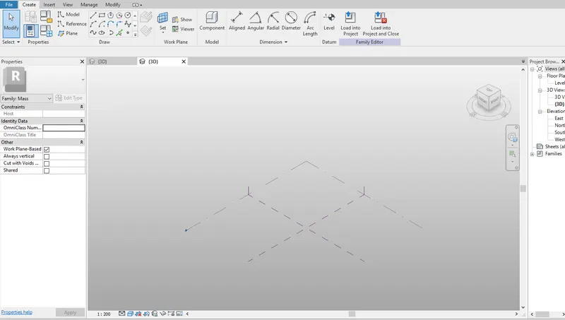
CREATE SPLINE COLUMN LINE
- Go to east elevation
- Click on model from modify tab then select pick line from draw tool
- Provide offset of 12’ from Level 1
- Go to level 1 floor plan
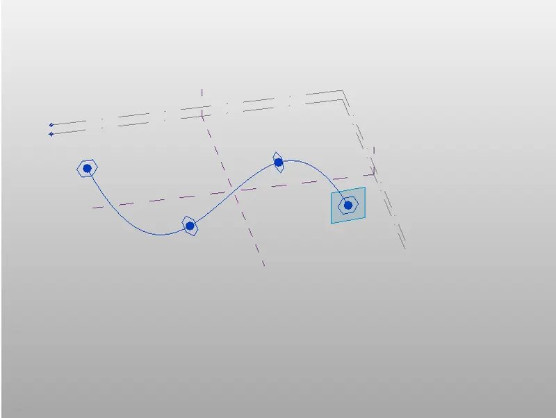
- In create tab select spline from draw tool and create 4 points
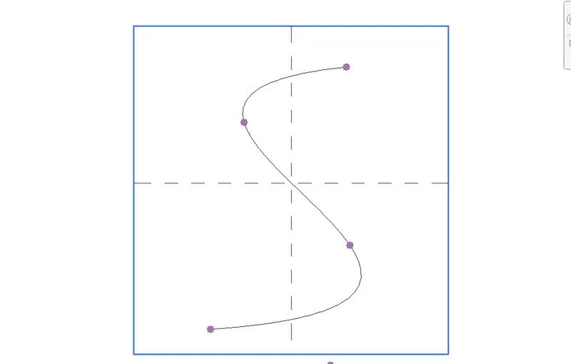
CONVERT INTO PARAMETRIC SOLID FORM
- In 3D view, select created column line
- Set plane at each created point
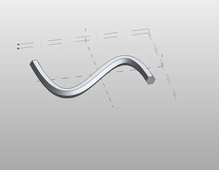
- Select polygon and create at all point with mass of 12’
- Again, select created column line and first polygon
- In modify tab, dropdown create form and select solid form
CONVERT SOLID FORM TO TRIANGULAR BENT
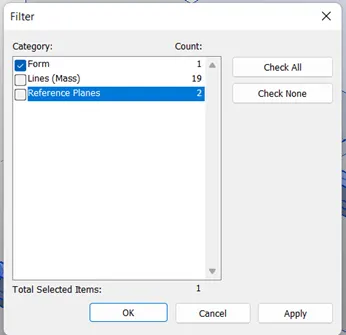
- Select only form with the help of filter
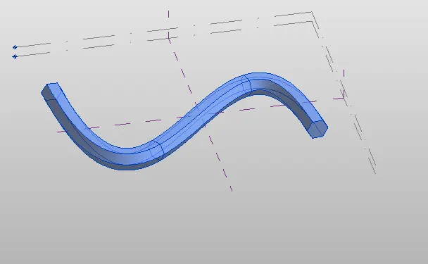
- Click on divide surface
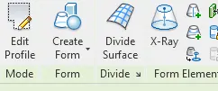
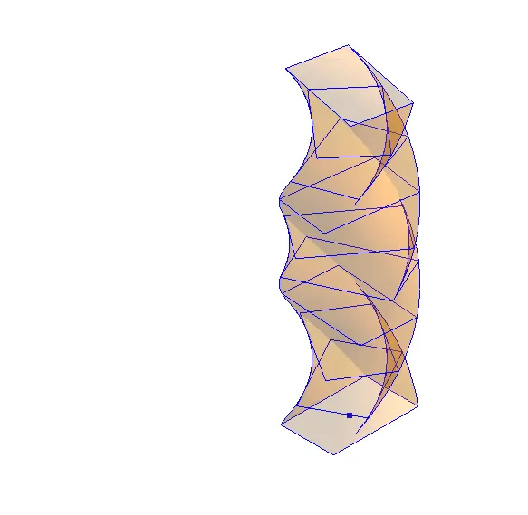
- Select the pattern Triangle bent
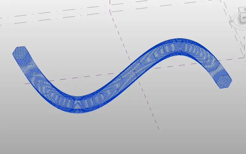
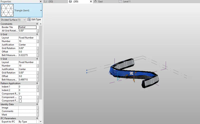
RESULT:-
- Successfully completed a conceptual mass in revit and developed a parametric column by dividing the surfaces and also applied the concepts similar to used in parametric walkway modelling.
5.
AIM:
By using dynamo created conceptual wall layout of floor plan
INTRODUCTION:
To create the conceptual layout of a floor plan in dynamo, used available tool for joining the line, wall type and floor type and used sliders for height and length of wall
PROCEDURE:
OPEN DYNAMO
- Open Revit software
- In new architectural template
- Go to manage tab, click on dynamo under visual programming
- Dynamo window will open
- Create a new dynamo model
PROVIDE HEIGHT AND LEVELS
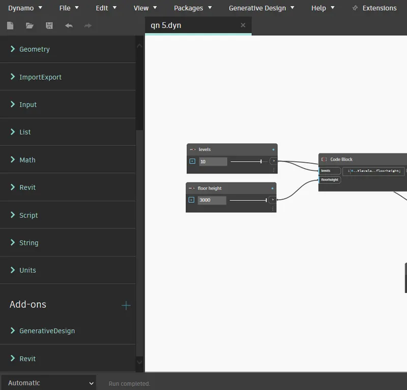
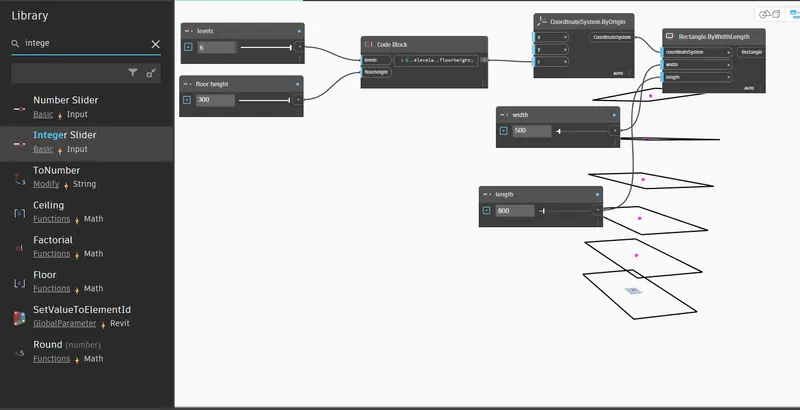
- Insert 2 Integer Slider and rename it i.e., Levels,floor Height
- Insert Code Block and provide code as “0..#Levels..FloorHeight”
PROVIDE HEIGHT AND LEVELS
- Insert CoordinateSystem.ByOrigin
- Provide the output of code block as an input to z point of CoordinateSystem.ByOrigin
- Change the no of Level and Height is integer slider
- This will create level on z axis
PROVIDE HEIGHT AND LEVELS
- Insert 2 Integer Slider and renamed with Width and Length
- Provide appropriate value to the sliders
- Insert Rectangle.ByWidthLength
- Provide input to Rectangle.ByWidthLength from Width, Length and CoordinateSystem.ByOrigin
- It obtains the rectangle on the z axis level
ROTATE THE LEVELS
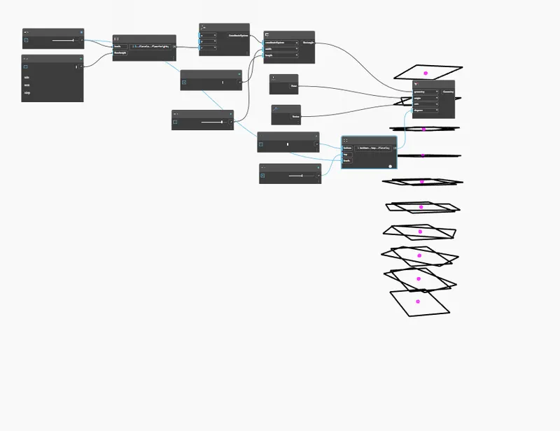
- Insert Code Block and provide the code as “Bottom..Top..#Levels”
- Connect the code Block with Bottom Top and Levels
- Insert Point.Origin and Vector.ZAxis
- Insert Geometry.Rotate and provide the input from Code Block, Rectangle.ByWidthLength, Point.Origin and Vector.ZAxis
CREATE SURFACE
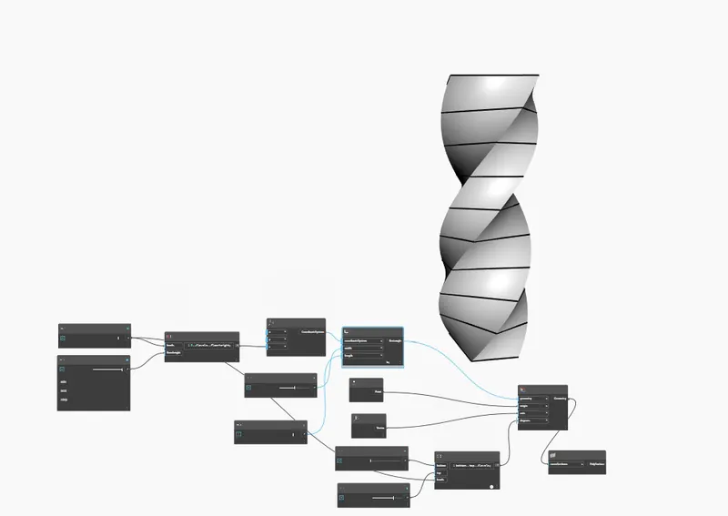
- Insert PolySurface.ByLayout
- Provide input from Geometry.Rotate
RESULT
Succesfully completed the parametric stadium as shown in the below figure.