Creating Conceptual mass in REVIT and Creation of Sinusoidal curve and a Parametric stadium using Dynamo
1) Using Dynamo create a set of sinusoidal points and create a curve and create a surface out of the curve.
Ans :
Aim : Using Dynamo create a set of sinusoidal points and create a curve and create a surface out of the curve.
Procedure :
- Open the revit the file and give the architeture template
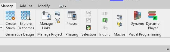
- And go to the mange tab in the ribbon tab and open the dynamo file
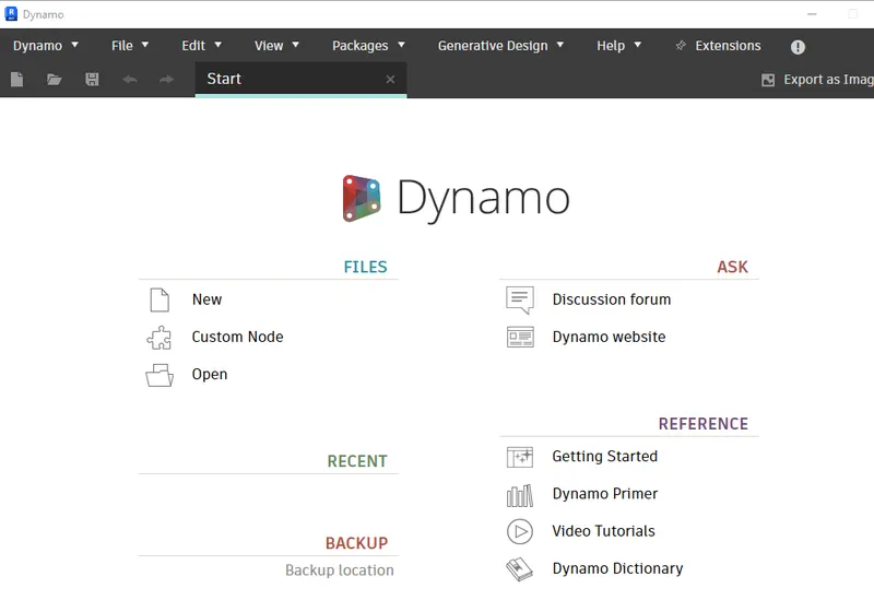
- Then open the new dynamo file window and created a new file
- And insert the 3 interger silder and rename that start point ,end point, And stop point
- And insert the Range and connect the 3 interger silder to the range
- And insert the 2 point.by coordinate and then connect to the list to the x -axis in the point.by coordinates
- And connect to the list to the other x- axis in the point.by coordinate
- And now enter the one code block and math sin
- Give the value to the code block and connect to the z- axis in the point.by coordinates
- And next range list is connect to the math.sin to the y - axis in the point.by coordinates
- Insert the product and connect the math.sin and point.coordinate to it .
- Insert the nurbs curve.bycontrol points And point .by coordinate connect to the points in the nurbs curvebycontrol points
- And insert one more nurbs curve .bycontrolpoints and product to the points in the nurbscurve.bycontrolpoint
- Then insert list create add item0and item1 and one nurbscurve.by control point the connect to the item0 and other nurbscurve.bycontroal point to the item1
- Insert the surface.byloft and connect list create to the surface.byloft.
- Then we creat a surface for the points .
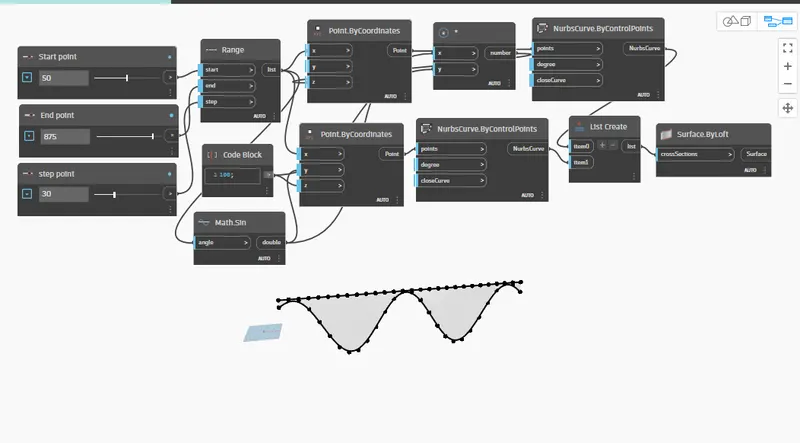
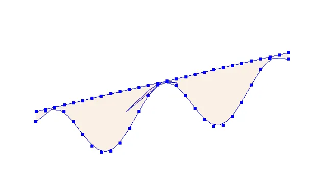
Result : Using Dynamo create a set of sinusoidal points and create a curve and create a surface out of the curve.
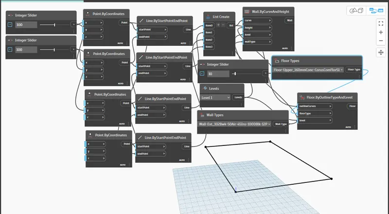
2) Create a conceptual layout of floor plan in dynamo . Using the tools available in dynamo link the lines to appropriate model elements in Revit by choosing the wall types and wall parameters. Make use of the sliders to slide through the height of the wall and length of the wall.
Ans :
Aim : Create a conceptual layout of floor plan in dynamo . Using the tools available in dynamo link the lines to appropriate model elements in Revit by choosing the wall types and wall parameters. Make use of the sliders to slide through the height of the wall and length of the wall.
Procedure :
- Open the revit the file and give the architeture template
- And go to the mange tab in the ribbon tab and open the dynamo file
- Then open the new dynamo file window and created a new file
- Insert the two integer slider and give the value for the it
- And insert the 4 ponit by coordinates
- And connect the one integer silder value to the frist x- axis in the point by coordinater and same connect to the y-axis of the second point by co-ordinater
- And connect the aecond integer silder value to the second x- axis in the point by coordinater and same connect to the y-axis of the third point by co-ordinater
- Now insert the four linebystart point end point to rectangle box
- And connect the first point by co-ordinater to the start point in the frist line by startendpoint and end point is connect to the second point by co-ordinater
- And connect the second point by co-ordinater to the start point in the second line by startendpoint and end point is connect to the Third point by co-ordinater
- And connect the Thrid point by co-ordinater to the start point in the Third line by startendpoint and end point is connect to the fouth point by co-ordinater
- And connect the fourth point by co-ordinater to the start point in the fourth line by startendpoint and end point is connect to the first point by co-ordinater
- Then we creat the rectangle for from this .
- Now insert the list create,integer slider ,levels,wall types
- In the list creat the four items and thos list connect to the four line.by startpoint and end point
- And Give the value for the integer side value and level and select the wall type
- Now to creat wall structure insert the wall.bycurveand height
- Now connect the list to the curve and integer silde to the height of the wall and level to the level and wall type to the wall type in the wall.bycurveandheight.
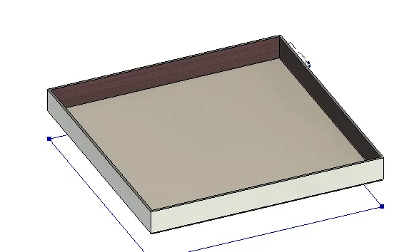
- we created the wall and now we use to provide the floor for it
- Frist the insert the floor type and select the floor type
- And insert the floor.byoutlinetype and level
- In this connect the list to the outline curves and floor type to the roof type and level to the level
- Then we creat a wall with the floor .
3) Create an array of model elements in Revit. Use dynamo to vary the properties of model elements by using the slider or code block
Aim:Create an array of model elements in Revit. Use dynamo to vary the properties of model elements by using the slider or code block
Procedure :
- First the revit file with the architecture template .
- And go to the architecture tab in the ribbon tab and select the architecture column
- And place four column for it .
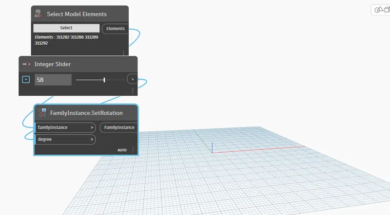
- Now go to the mange tab open the dynamo file and creat the new file for it
- To rotate the column creat the code block in the dynamo
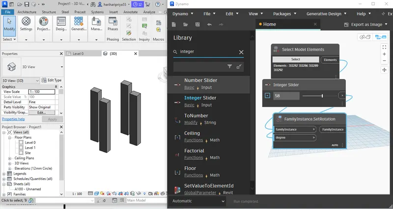
- How insert the one select model element and integer silder and familyinstance.setRotation
- now to the select model element to select go to the revit file and select the four element init
- And give the integer silder valu fo the rotation
- now both select model element and integer silder to the family instance set rotation .
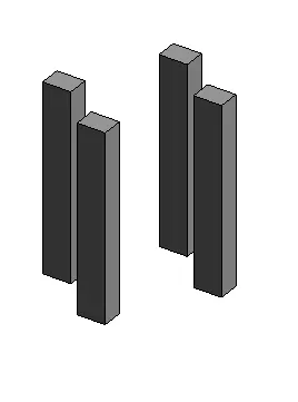
Result : Create an array of model elements in Revit. Use dynamo to vary the properties of model elements by using the slider or code block
4) Create a conceptual mass in Revit and develop a parametric column by dividing the surfaces and apply the concepts similar to used in parametric walkway modelling. Use triangular bent or square shaped panels to add finish to the parametric column
Aim : Create a conceptual mass in Revit and develop a parametric column by dividing the surfaces and apply the concepts similar to used in parametric walkway modelling. Use triangular bent or square shaped panels to add finish to the parametric column
Procedure :
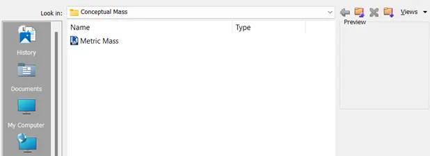
- Open the revit file and go to file tab open the conceptual mass folder and open it
- And select the metric mass and open it
- And go to the elevation and give the height using the line to draw it and provide the offset of 12'
- And go to the level and open the floor plan
- creat the spline from the drawing tool and create the points
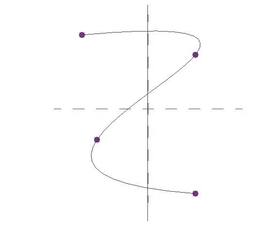
- And now go to the 3d view and set plan at the created points
- Now select the polgon and created at all point with mass of 12'
- And select the splin line and polgon created the soild form
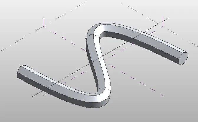
- select the filter and select only form
- and now select the object and change the property of pattern And give the triangle bent
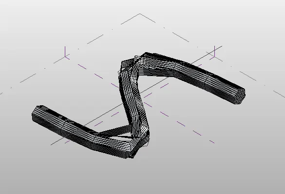
Result : triangular bent or square shaped panels to add finish to the parametric column
5) Use Dynamo to work on developing a Parametric Stadium. List your parameters and use the visual programming approach to complete the modelling, You can use the concepts discussed in parametric high rise tower in class for reference.
Aim : Use Dynamo to work on developing a Parametric Stadium. List your parameters and use the visual programming approach to complete the modelling, You can use the concepts discussed in parametric high rise tower in class for reference.
Procedure :
- Open the revit the file and give the architeture template
- And go to the mange tab in the ribbon tab and open the dynamo file
- Then open the new dynamo file window and created a new file
- Insert 2 integer slider and remane as No of levels and floor to floor height
- Now insert the code block and give the code for it is 0..#levels ..Floor height
- connect the noof levels and floor to floor to the code block .
- Insert the co-ordinate system .byorigin ,connect the code block to the co-oridinate systemby.origin.
- Insert the 4 integer slider and rename as width,Length,Bottom Floor rotation, Top Floor rotation .
- Insert the rectangle by width length and connect the width ,length,co-oridinate system
- inser the code block and write the code as Rotate ..top..#levels
- connect Bottom floor rotation,top floor rotation and no of levels to the code block
- Insert the point origin ,vector Z axis , Geometry .Rotate
- Now connect the Rectangle .by width length,point origin ,vector Z axis ,code block to the Geometry .Rotate
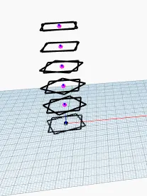
- Insert surface by loft and connect the Geometry .Rotate to the Surface by loft.
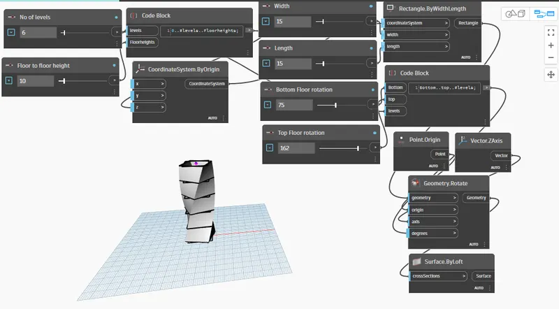
Result : parametric high rise tower