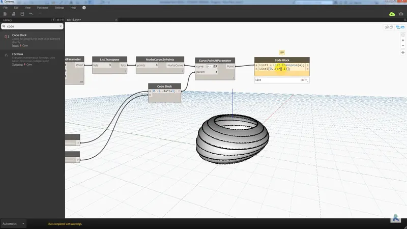
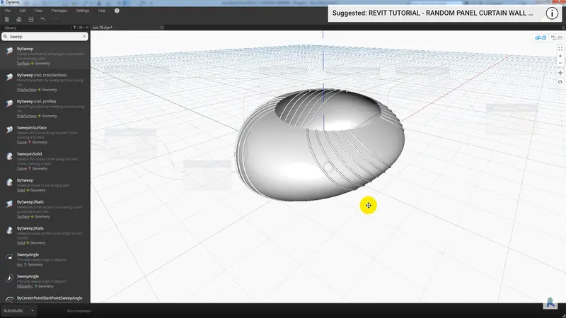
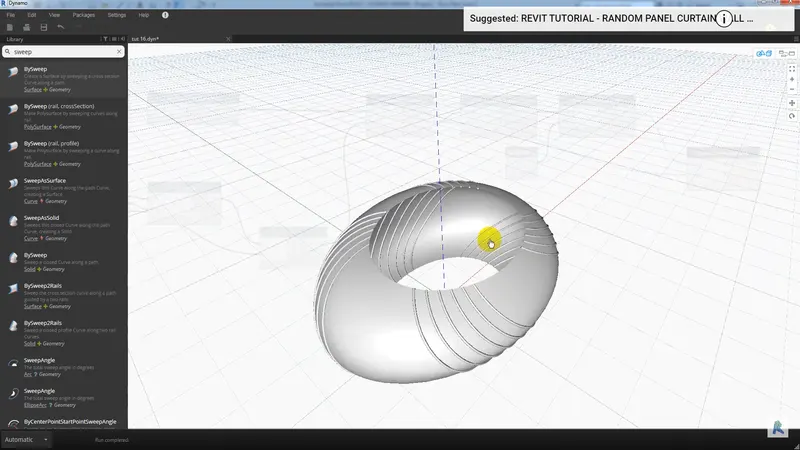
Creating Conceptual mass in REVIT and Creation of Sinusoidal curve and a Parametric stadium using Dynamo
Q.1
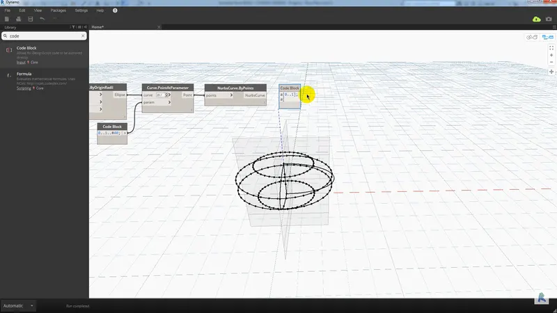
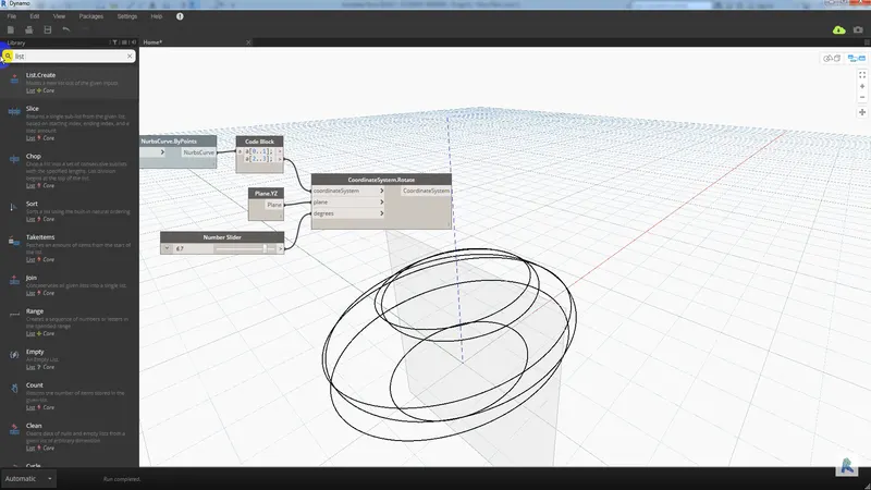
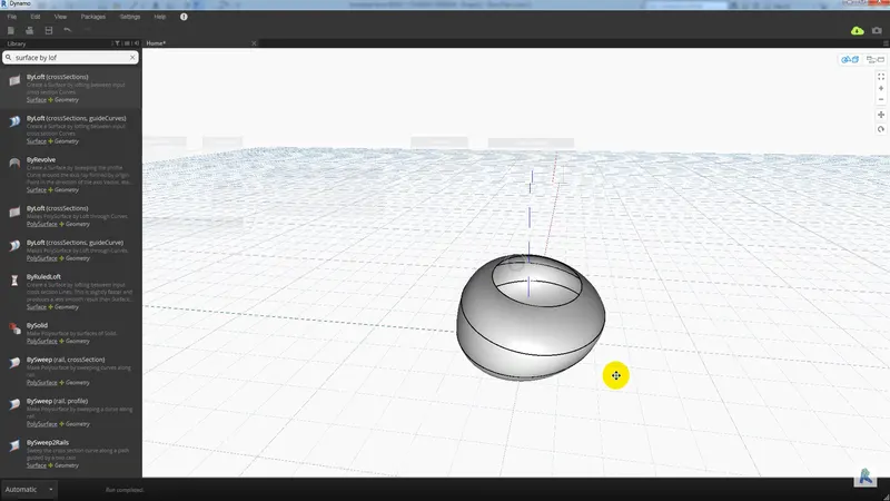
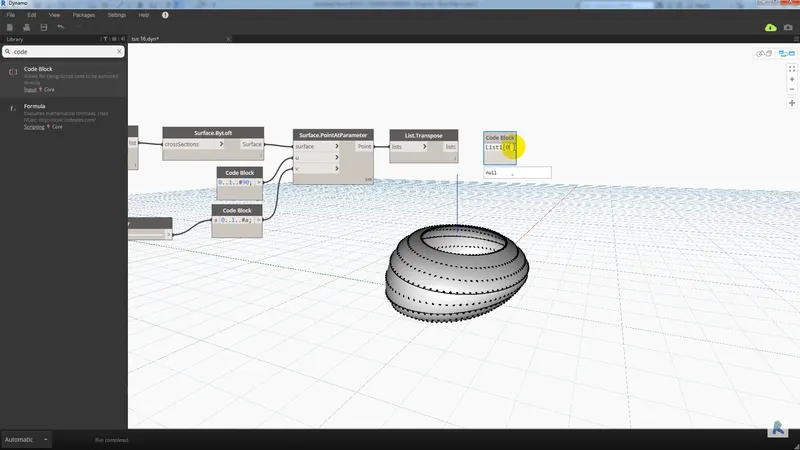
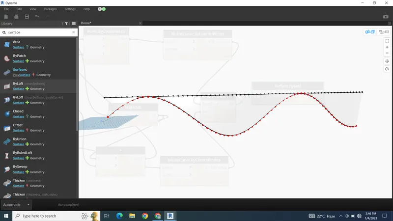
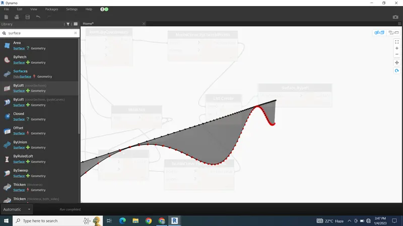
AIM - Using Dynamo create a set of sinusoidal points and create a curve and create a surface out of the curve.
PROCEDURE -
To create sinusoidal curves first open Revit then go to the manage tab then click dynamo
Open dynamo and start with new file
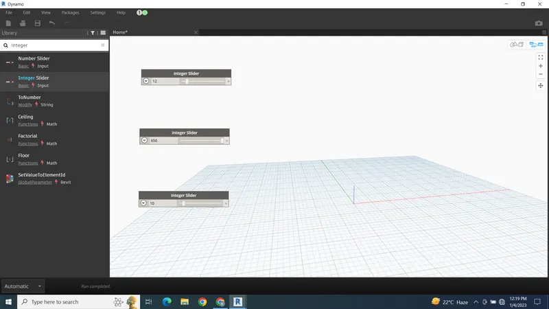
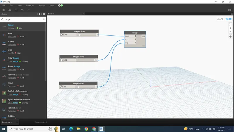
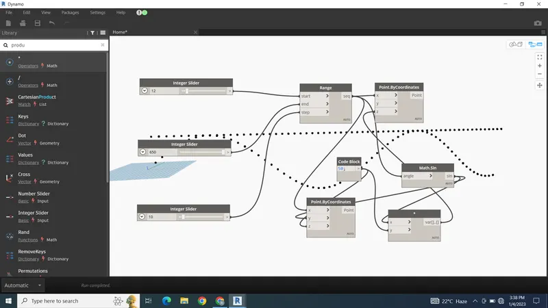
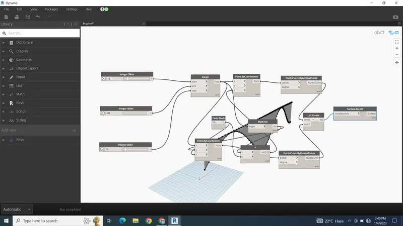
First add the integer sliders
Set the sliders and required limits
Then add the range block connect the slider to the range block
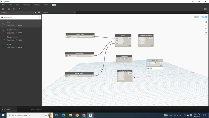
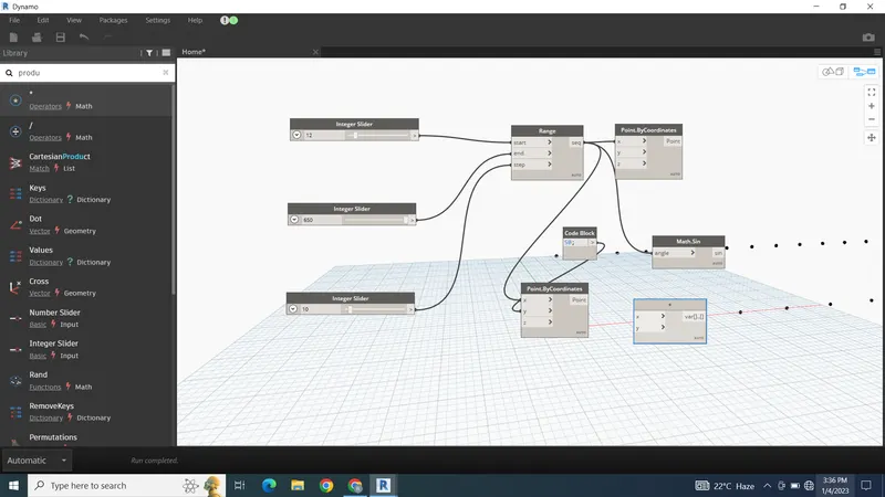
Then add points by coordinates conned the range block to the X co ordinate
Then add the math sin. Connect the range block to the math sin
Then create the code block and connect both code block and range block to the product
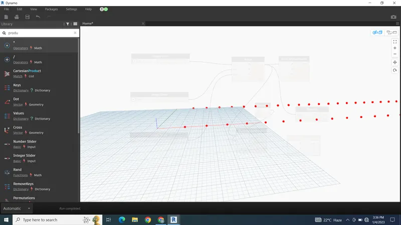
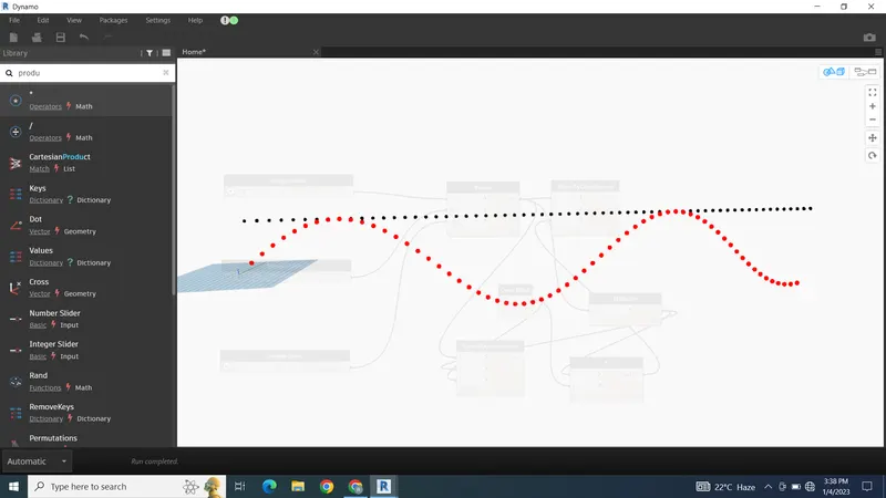
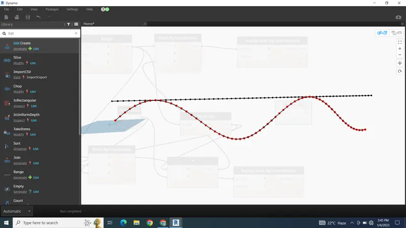
Then connect the product to the Z coordinate the first curve will be crated
To create the second curve add the 2nd coordinate block and connect the code block to Y coordinate , range block to X and product to Z ordinate the 2nd cure will be created
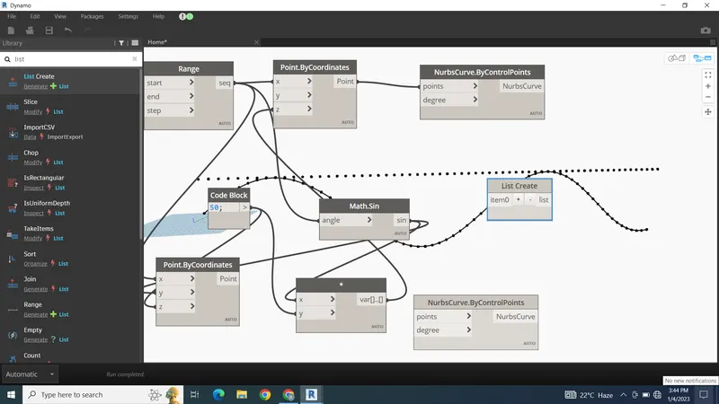
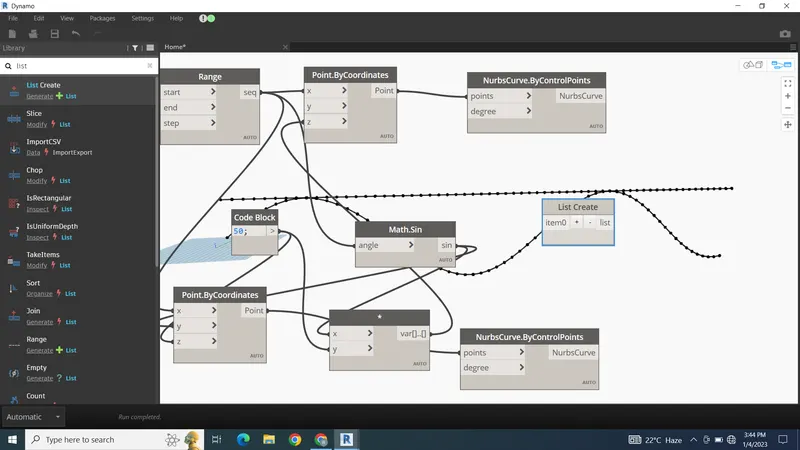
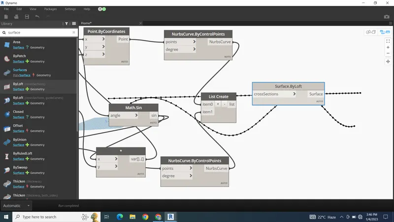
Then add two blocks of nurbs curve and connect the coordinates of both the curve to the nubs curve
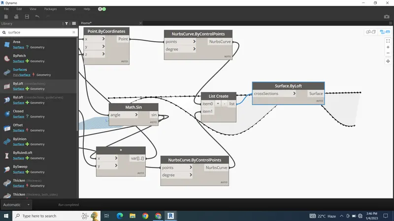
Then make the list of curves
And add the surface by loft
RESULT -
Q.2
AIM - Create a conceptual layout of floor plan in dynamo . Using the tools available in dynamo link the lines to appropriate model elements in Revit by choosing the wall types and wall parameters. Make use of the sliders to slide through the height of the wall and length of the wall.
PROCEDURE -
To create the wall and floors first open revit then open dynamo
Then create new file
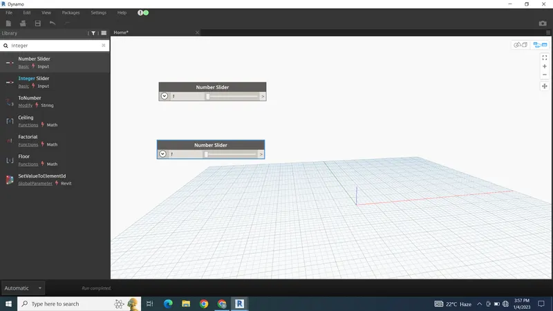
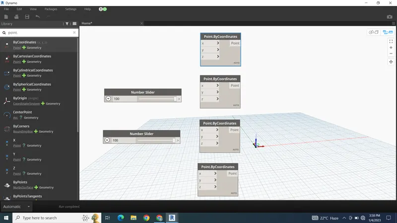
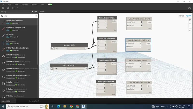
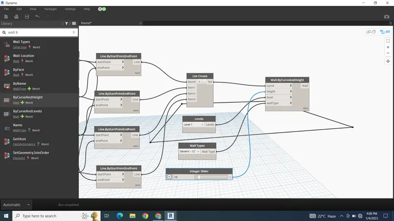
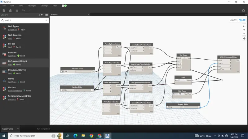
Then add 2 integer sliders and 4 points by coordinates
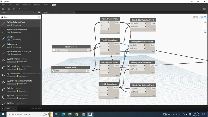
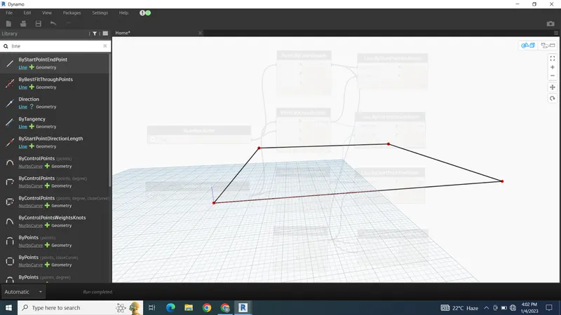
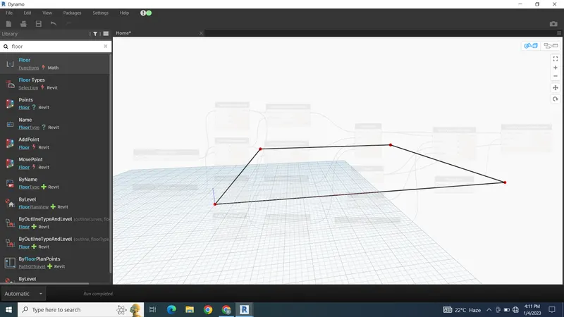
Then connect the sliders to the co ordinated to create the points as rectangle
Then create the line by start point connect the co ordinates to the line block to create the line
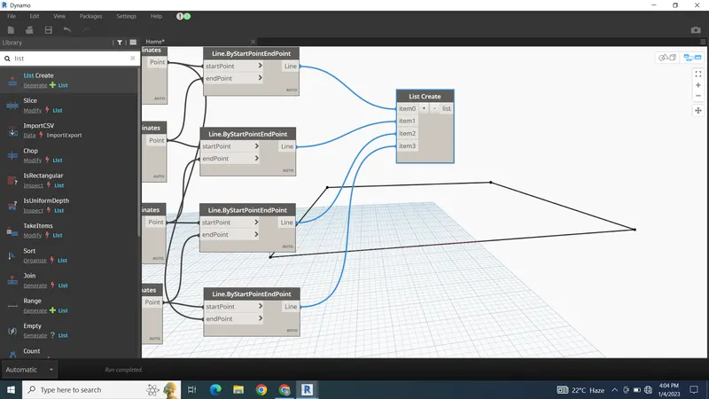
Then create the list of lines
And create the wall by wall by curve and height
For curve connect the list for height add the slider for levels add levels for wall type add wall type
To create the floor use floor by outline type and leveL
For outline connect list for floor type add floor type for levels connect levels
RESULT -
Q.3
AIM - Create an array of model elements in Revit. Use dynamo to vary the properties of model elements by using the slider or code block.
PROCEDURE -
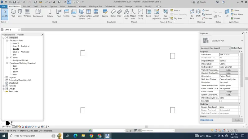
First create column array in the revit by using architectural column
Then open the dynamo
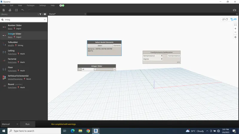
Then add select model elements and integer slider and set rotation
Select the columns and set the slider to 45
Then connect slider and model elements to the rotation block
The columns will be rotated at 45 degrees
RESULT -
Q.4
AIM- Create a conceptual mass in Revit and develop a parametric column by dividing the surfaces and apply the concepts similar to used in parametric walkway modelling. Use triangular bent or square shaped panels to add finish to the parametric column
PROCEDURE -
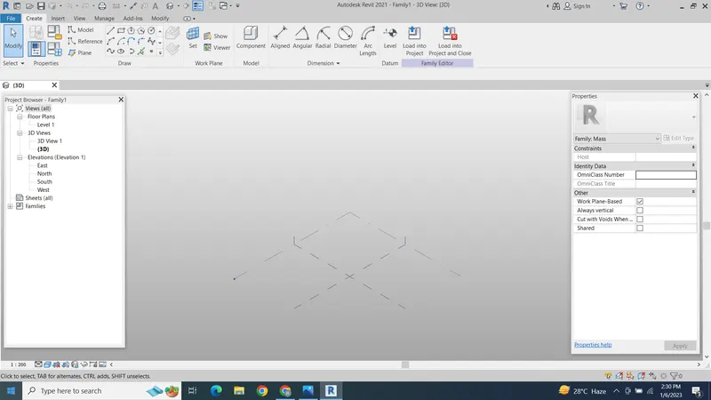
To create the parametric struc. First open the the conceptual mass template
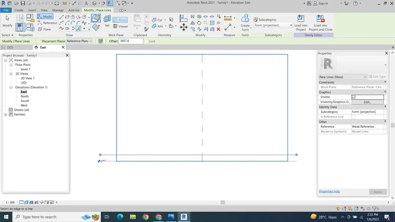
Then create the 4m level
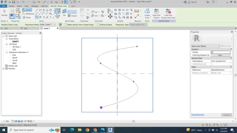
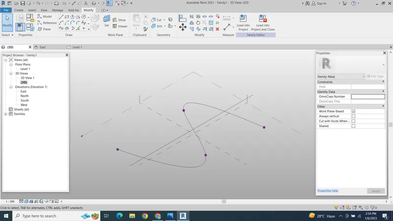
Then create the spline shape
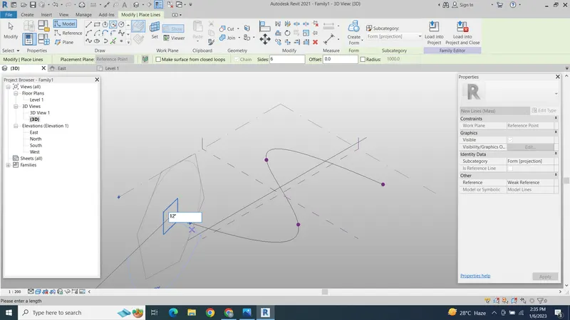
Then create the plane at point
And add the shape to the set plane
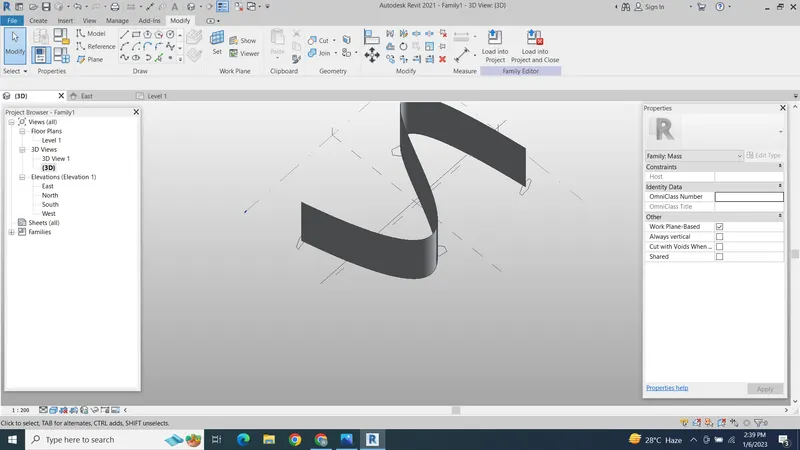
Then select the spline and curve and create the mass
Then select the foam and split the plane and give the triangular bent option to the planes
RESULT -
Q.5
AIM - Use Dynamo to work on developing a Parametric Stadium. List your parameters and use the visual programming approach to complete the modelling, You can use the concepts discussed in parametric high rise tower in class for reference.
PROCEDURE -
To create the parametric building first open REVIT then open the dynamo
Then first add 4 sliders one for no of floors 2nd for floor to floor height 3rd for bottom rotation angle 4th for top rotation angle
Then add code block and write a code for levels and floor height
Then add co ordinate system connect code block to the Z axis
Then add slider for width and length of building
Then add block for rectangle by width and length connect the co ordinate and with and length to the block
Then to rotate the building add rotation block connect the rectangle as geometry connect point origin to origin and vector Z axis to axis and for angle add the code block and connect the top and bottom rotation sliders
Then to add surface to the model use poly surface by loft and connect rotaion geometry to the surface block
RESULT -