Creating a Floor plan, Footing detail and Isometric view using AutoCad
C-1
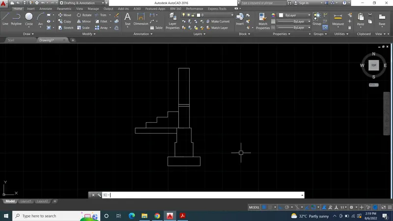
Aim - Drawing C.S. of load bearing wall over spread footing.
Procedure -
- Start the auto cad and set up the unit to metric.
- Then select the rectangle tool and draw the rectangle of 0.90 x 0.25 as per given in the drawing.
- Select tool polyline and draw the steps 0.50x0.40 and 0.40x0.40 as per drawing.
- select the line tool and draw the G.L of 1.15.
- Again select polyline and draw the bottom portion of column of 0.30x0.60.
- Complete the upper portion of column by using rectangle tool.
- Then draw the steps using either line tool or polyline tool. Size - 0.30x0.15
- Finish the drawing.
Result - by using the above procedure i draw this drawing in auto cad.
C-2
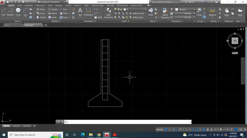
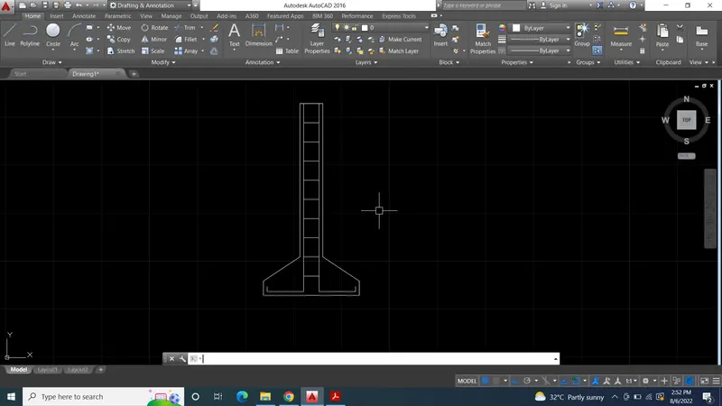
Aim - Drawing C.S of ISOLATED FOOTINg
Procedure -
- Start the auto cad and set up the unit to metric.
- Using line or polyline tool draw the base of the footing as per sizes given in the drawings.
- select the line tool and draw column of height 1.60.
- Then start the darwing of reinforcement.
- Then using line tool and offset tool draw the column reinforcement as per sizes given in the drawing.
- Again using line tool sketch the reinforcement of footing and finish the drawing.
Result - By using about procedure i draw this drawing using auto cad.
C-3 -
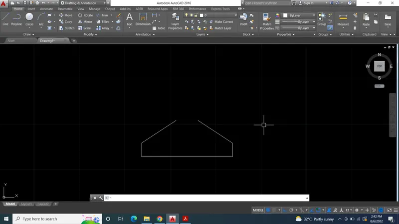
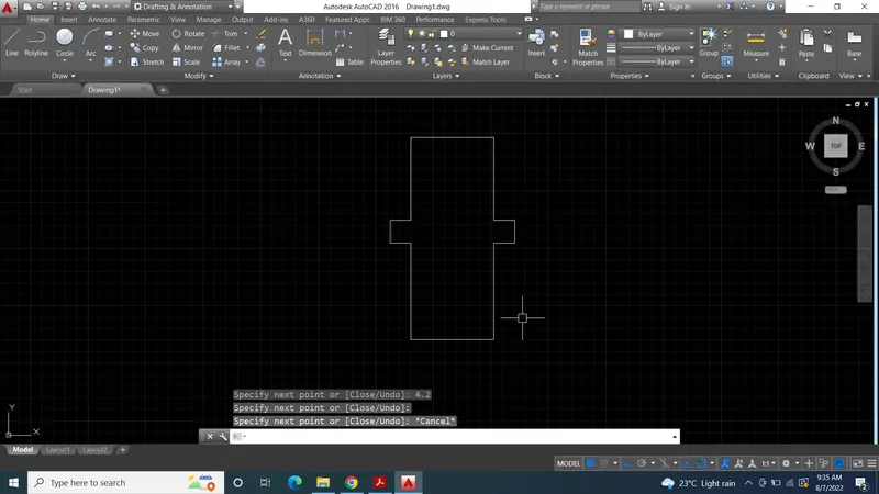
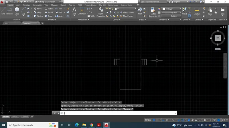
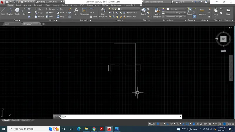
Aim - SKETCHING LINE DIAGRAM OF TWO BEDROOM BUILDING USING AUTO CAD.
Procedure -
- Start the auto cad and set up unit to metric using unit dialog box.
- Select line tool and draw outline of the plan as per given diamentions.
- Select offset tool and draw the steps. Offset -0.30
- Again select the line tool and draw the internal walls using line tool.
Result -
C-4-
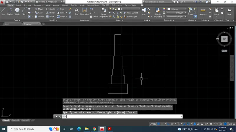
Aim - SKETCHING C.S OF LOAD BEARING WALL SHOWING FOUNDATION DETAILS.
Prodecure -
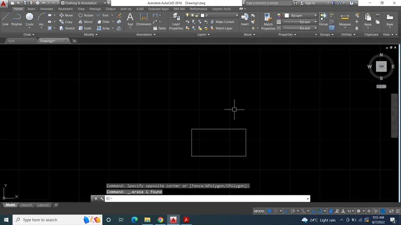
- Open the auto cad in P.C and set up the unit to metric and precision to 0.00.
- Select rectangle tool and draw the bottom step of 0.90x0.45.
- Then select line or polyline command and sketch the upper steps as showwing in drwing.
- 1st mark the point of 0.15 freom the top corner on base step.
- Using poly line tool sketch the above steps of sizes i.e 0.50x0.40 and 0.40x0.30 .
- Then select line tool and sketch the wall of size 1x0.30.
Result - By using above procedure i draft this drawing.
C-5-
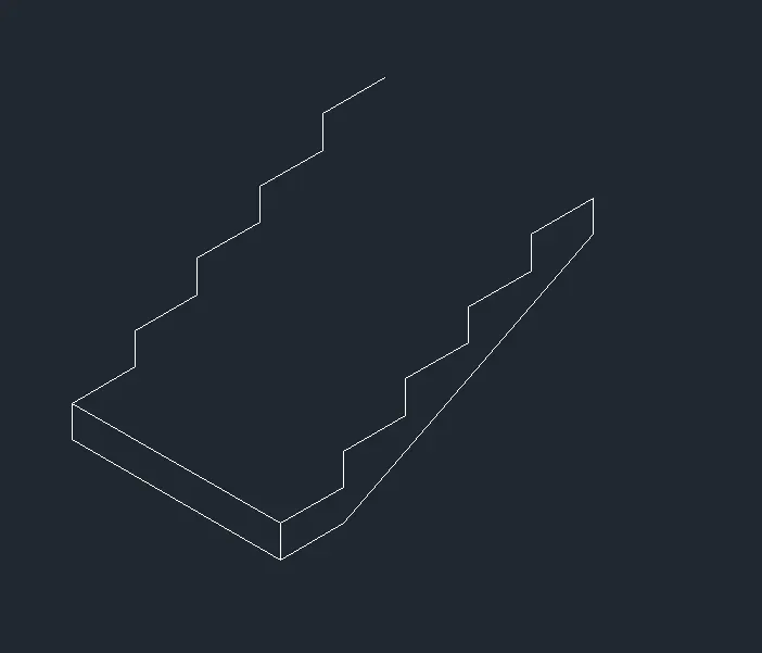
Aim - Sketching Isometric view of steps using auto cad
Procedure -
- Start the auto cad and set up the unit to metric using unit dialog box.
- Turn on the isometric grid.
- Select line and draw one step as per sizes given in the drawing.
- Copy that step select one point of step and paste it one over another.
- complete the remaining part using necessary tools.
Result -

C-6 -
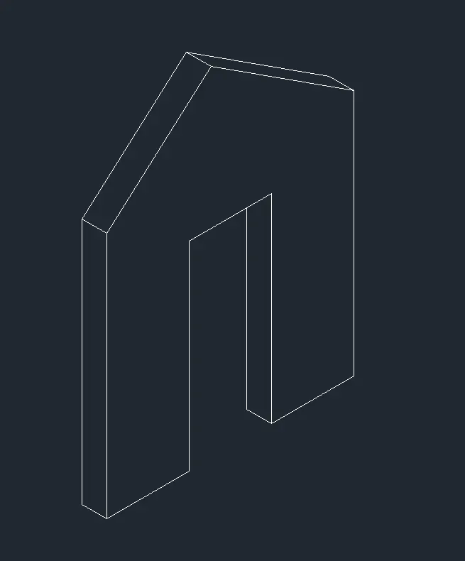
Aim - Sketching Isometric view of gable wall.
Procedure -
- Start the auto cad and set up the unit to metic.
- Turn on the isometric grid.
- Sketch the drawing as per sizes given in the drawing.
Result -